Note: Descriptions are shown in the official language in which they were submitted.
.131 ~ ~~ I
CA 02387293 2002-05-23
IMPROVED ENGINEERED ABRASIVES
Background of the Invention
This invention relates to the production of engineered abrasives on
substrates in a form useful for grinding and finishing of substrates suclh as
metals,
wood, plastics and glass
The proposal to deposit generally isolated structures such as islands or
ridges of a mixture of a binder and abrasive material on a backing mal:erial
to form
so-called "engineered abrasives", has been known for many years. If the
islands or
ridges have very similar heights above the backing and are adequately
separated
then, (perhaps after a minor dressing operation), use of the product will
result in
reduced surface scratching and improved surface smoothness. In addition the
spaces between the islands provide a route by which swarf geneirated by the
abrasion can be dispersed from the work area and coolant can circulate.
In a conventional coated abrasive, investigation of the grinding surface
reveals that a comparatively small number of the surface abrasive grits in an
active
abrading zone are in contact with the workpiece at the same time. Aa the
surface
wears, this number increases but equally the utility of some of those
<~brasive grits
- may be reduced by dulling. The use of structured abrasives has the advantage
that
the uniform islands wear at essentially the same rate such that a uniform rate
of
abrasion can be maintained for longer periods. In a sense the abrading work is
more evenly shared among a larger number of grinding points. Moreover since
the
islands comprise many smaller particles of abrasive, erosion of an island
uncovers
new, unused abrasive particles which are as yet undulled.
One technique for forming such an array of isolated islands or dots that has
been described is that of the rotogravure printing.The technique of
rotogravure
printing employs a roll into the surface of which a pattern of cells has been
engraved. The cells are filled with abrasivelbinder formulation and the roll
is
pressed against a surface and the formulation in. the cells is transferred to
the
surface.
Chasman et al. in USP 4,773,920 disclosed that using a rotogravure water,
it is possible to apply a uniform pattern of ridges and valleys to the binder
formulation which, when cured, can serve as channels for the removal of
lubricant
and swarf. However beyond the bare statement of possibility, no details are
given
ui ~i,
CA 02387293 2002-05-23
that might teach how this might be carried out.
In USP 4,644,703 Kaczmarek et al. used a rotogravure roll in a more
conventional fashion to deposit an abrasivelbinderformulation to deposit: a
layerthat
is then smoothed out before a second layer is deposited by a rotogravure
process
on top of the smoothed-out first layer. There is no teaching of the naturE: of
the final
cured surface.
In USP 5,014,468 (Ravipati et al.) it was proposed to use an abrasivelbinder
mixture having non-Newtonian flow properties and to deposit this mixture by a
rotogravure technique on to a film. In this process the mixture was deposited
from
the edges of the rotogravure cells to produce a unique structures with
deposits of
reducing thickness with distance away from the surface surrounding areas
devoid
of the mixture: If the cells are sufficiently close together, the surface
stwctures can
appear interlinked. This product has proved very useful, particularly in
ophthalmic
fining operations. A further refinement of such a rotogravure process was
described
in USP 5,840.088. The process is very useful but it has a potential problem
with
increasing build-up of material in the cells of the rotogravure roll such that
the
deposition pattern can change slightly during a protracted production run. In
addition the nature of the process is such that it is lunited to formulations
containing
relatively fine abrasive grits, (usually less than 20 microns).
Another approach to making engineered abrasives is provided by depositing
an abrasivelbinder mixture on a substrate surface and then imposing a pattern
comprising an array of isolated structures on the mixture by curing the binder
while
in contact with a mold having the inverse of the desired patterned surface.
This
approach is described in USP 5,437,754; 5,378,251; 5,304,223 and 5,152,917.
There are several variations on this theme but all have the common feature
that
each structure in the pattern is set by curing the binder while the composite
is in
contact with a molding surface.
In USP 5,8fi3,306 Wei et al. described another techniquE: for making
engineered abrasives by an embossing process applied to an abrasive (curable
binder mixture.
USP 5,833,724 (Wet et al.) refined engineered abrasive structures, deposited
2
~.. r~i. ~,~i~.
CA 02387293 2002-05-23
by any prior art technique; by the superposition of a "functional powder" over
the
engineered surface. This functional powder can be abrasive particles or a
grinding
aid or any other additive conveying a specific advantageous property on the
engineered abrasive surface. Most often the powder is a mixture of abrasive
particles and a grinding aid. Such a functional powder provides a very'
aggressive
initial cut that is highly desirable.
The present invention provides an added improvement to this ~;oncept that
ensures maximum benefit from the functional powder coating.
General Description of the Invention
It has now been found that a coated abrasive can be made wherein the
surface is engineered to comprise a plurality of shaped composites attached to
a
common backing material, said composites comprising a UV-cured resin with
abrasive particles dispersed therein, and the surface of the shaped abrasive
composites having a lager of particles of a functional powder adhered thereto
characterized in that a top size coat overlies the functional powder
particles.
The "top size coat" is a layer comprising a cured binder which is deposited
overthe functional powder and acts to help retain the particles of powder in
position
during grinding. As the name indicates it is the topmost layer of the coated
abrasive
and is therefore the layer that first contacts a workpiece when the coated
abrasive
is in use. The top size coat can also comprise other non-abrasive components
such as a filler or a pigment to modify the physical properties andlor
appearance of
the surface. The binder can be a thermosetting resin or a radiation curable
resin.
Examples of such resins include phenollformaldehyde resins; urealformaldehyde
resins; epoxy resins; (meth)acrylate polymers and copolymers; urethane
(meth)acrylate resins; polyester/(meth)acrylate resins; epoxy-(meth)acrylate
resins
and other resins known in the art for such applications.
It is preferable that the top size layer is compatible with the layer over
which
it is applied. This is preferred to ensure that the cured top size layer will
not flake
off the layer immediately below under grinding conditions. For example
composites
in which the cured binder is an acrylate-based radiation-cured binder can be
over
3
CA 02387293 2005-O1-28
laid by a top layer that is also an acrylate resin, an epoxy resin or a
phenolic resin.
The invention is particularly useful when the engineered abrasive surface
comprises a coating of a functional powder, separately applied and bonded to
the
surface or applied to the UV-curable binder/abrasive mixture from which the
composites are formed before cure of the binder such that the powder is
concentrated in the surface layer of the composites as taught in USP
5,833,724.
In the present application the term "functional powder" is used to refer to
finely divided material that modifies the abrasive qualities of the engineered
abrasives to which it is applied. This can be as simple as making the
engineered
abrasive cut more aggressively or reducing the buildup of swarf or static
charge on
the surface. Some functional powders can additionally serve as a releasing
agent
or a barrier between the resin formulation and the embossing tool, reducing
sticking
problems and allowing improved release. Included underthe heading of
"functional
powders" are fine abrasive grits, grinding aids, anti-static additives,
lubricant
powders and the like. The individual particles of the powder typically have an
average particle size, (D~), less than about 250 micrometers such as from 1 to
150
micrometers and more preferably from 10 to 100 micrometers.
Drawincts
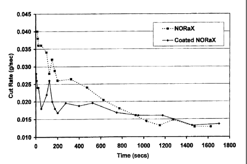
Figure 1 is a graph showing the variation of cut rate with time in the
comparative
evaluations in Example 1. Figures 2 and 3 also refer to the data generated in
the
same Example and compare variations of pattern height with time, (Figure 2),
and
cumulative abrasive volume loss with time, (Figure 3). Figure 4 refers to the
Example 2 data and is a graph of cut rate against number of passes for
different
top size coat formulations.
Detailed Description of the Invention
The formation of the engineered abrasive surface can be by any of those
techniques known in the art in which a slurry composite of abrasive and a
binder
precursor is cured while in contact with a backing and a production tool so as
to be
adhered on one surface to the backing and, to have imposed on the other
surface
the precise shape of the inside surface of the production tool . Such a
process is
described for example in USPP 5,152,917;5,304,223; 5,378,251 and 5,437, 254.
4
CA 02387293 2005-O1-28
Alternative formation methods, including rotogravure coating, are described
in USPP 5,014,468 and 4,773,920.
The surface of the engineered abrasive can have any desired pattern and this
is determined in large part by the intended purpose of the coated abrasive
product.
It is for example possible to provide that the surface is formed with
alternating ridges
and valleys oriented in any desired direction. Alternatively the surFace may
be
provided with a plurality of projecting composite shapes which may be
separated or
interconnected and either identical or different from adjacent shapes. Most
typically
the surface of the engineered abrasives have substantially identical shapes,
or
groups of repeating shapes, in predetermined patterns across the surface of
the
coated abrasive. Such shapes may be in the form of pyramids with square or
triangular bases or they may have more rounded shapes without clear edges
where
adjacent planes meet. The rounded shapes may be circular in cross-section or
be
elongated depending on the conditions of deposition and the intended use. The
regularity of the shapes depends to some extent on the intended application.
More
closely spaced shapes, for example more than about 1000 per square centimeter,
are favored for fine finishing or polishing while more aggressive cutting is
favored by
more widely spaced shapes.
The abrasive component of the formulation can be any of the available
materials known in the art such as alpha alumina, (fused or sintered ceramic),
silicon
carbide, fused alumina/zirconia, cubic boron nitride, diamond and the like as
well as
the combination of thereof. Abrasive particles useful in the invention
typically and
preferably have an average particle size from 1 to 150 micron, and more
preferably
from 1 to 80 micron. In general however the amount of abrasive present
provides
from about 10 to about 90%, and preferably from about 30 to about 80%, of the
weight of the formulation.
The other major component of the formulation is the binder. This is a curable
resin formulation selected from radiation curable resins, such as those
curable using
electron beam, UV radiation or visible light , such as acrylated oligomers of
acrylated
epoxy resins, acrylated urethanes and polyester acrylates and acrylated
monomers
'~ sr.. ~ i , i
CA 02387293 2002-05-23
including monoacrylated andlor multiacrylated monomers. Indeed it is often
convenient to have a radiation curable component present in the formulation
that
can be cured relatively quickly after the formulation has been deposited so as
to add
to the stability of the deposited shape. In the context of this application it
is
understood that the term "radiation curable" embraces the use of visible
light,
ultraviolet (UV) light and electron beam radiation as the agent bringing about
the
cure. In some cases the thermal cure functions and the radiation cure
functions can
be provided by different functionalities in the same molecule. This is often a
desirable expedient.
The resin binderformulation can also comprise a non-reactive them~oplastic
resin which can enhance the self sharpening characteristics of the deposited
abrasive composites by enhancing the erodability. Examples of such
thermoplastic
resin include polypropylene glycol, polyethylene glycol, and polyoxypropylene-
polyoxyethylene block copolymer, etc.
Fillers can be incorporated into the abrasive slurry formulation to modify the
rheology of formulation and the hardness and toughness of the cured binders.
Examples of useful fillers include: metal carbonates such as calcium
carbonate,
sodium carbonate; silicas such as quartz, glass beads, glass bubbles;
~~ilicates such
as talc, clays, calcium metasilicate; metal sulfate. such as barium sulfate,
calcium
sulfate, aluminum sulfate; metal oxides such as calcium oxide, aluminum oxide;
and aluminum trihydrate.
The abrasive slurry formulation from which the~structured abrasive is formed
can also comprise a grinding aid to increase the grinding efficiency and cut
rate.
Useful grinding aids can be inorganic based, such as halide salts, for example
sodium cryolite, potassium tetrafluoroborate, etc.; or organic based, such as
chlorinated waxes, for example polyvinyl chloride. The preferred grinding aids
in this
formulation are cryolite and potassium tetrafluoroborate with particlE; size
ranging
from 1 to 80 micron, and most preferably from 5 to 30 micron. The weight
percent
of grinding aid ranges from 0 to 50%, and most preferably from 10 ;~0%.
The abrasivelbinder slurry formulations used in the practice of this invention
may further comprise additives including: coupling agents, such as silane
coupling
6
CA 02387293 2005-O1-28
agents, for example A-174 and A-1100 available from Osi Specialties, Inc.,
organotitanates and zircoaluminates; anti-static agents, such as graphite,
carbon
black, and the like; suspending agents, viscosity modifiers such as fumed
silica, for
example Cab-O-Sil M5, Aerosil 200; anti-loading agents, such as zinc stearate;
lubricants such as wax; wetting agents; dyes; fillers; viscosity modifiers;
dispersants;
and defoamers.
Depending on the application, the functional powder deposited on the slurry
surface can impart unique grinding characteristics to the abrasive products.
Examples of functional powders include: 1 ) abrasive grains - all types and
grit sizes
; 2) fillers - calcium carbonate, clay, silica, wollastonite, aluminum
trihydrate, etc.; 3)
grinding aids - KBF4, cryolite, halide salt, halogenated hydrocarbons, etc.;
4) anti-
loading agents - zinc stearate, calcium stearate, etc., 5) anti-static agents -
carbon
black, graphite, etc., 6) lubricants -waxes, PTFE powder, polyethylene glycol,
polypropylene glycol, polysiloxanes etc..
The backing material upon which the formulation is deposited can be a
fabric, (woven, non-woven or fleeced), paper, plastic film or metal foil.
Generally,
the products made according to the present invention find their greatest
utility in
producing fine grinding materials and hence a very smooth surface is prefer-
ed.
Thus finely calendered paper, plastic film or a fabric with a smooth surface
coating
is usually the preferred substrate for deposition of the composite
formulations
according to the invention.
The invention will be further described with respectto the following Examples
which are understood to be for the purposes of illustration only and imply no
necessary limitation on the scope of the invention.
Exam~~le 9
In this Example the basic product was a commercial product sold
commercially as NORaX 0466 X110. This product is a coated abrasive with an
engineered surface comprising a random trihelical pattern of raised composites
comprised of P150 grit silicon carbide abrasive grain dispersed within a cured
acrylate resin binder. The surFace of the composites comprises a layer of a
functional powder consisting of a blend of P150 silicon carbide abrasive grit
and
* Trademark
CA 02387293 2002-05-23
potassium fluoroborate applied and adhered prior to the cure of the acrylate
resin.
In the test described below this is referred to as simply "NORaX".
This basic product was compared with the product according to the invention
in which the basic product was given a top size coat of a liquid one-stE;p
phenolic
resin obtained from Oxychem under the designation F'lyophen 43575. This was
applied using a two roll coater device. The treated coated abrasive was cured
over
12 hours at a temperature that was increased in linear fashion from 85.6"C to
121 °C
over ten hours and was maintained at the higher temperature for two hours.
This is
referred to hereafter as "Coated NORaX"
Both products were converted into 5 cm x 335.5 cm belts and tested in a low
speed, intermediate pressure, (2320 sfpm,15 psi), grinding test with titanium
as the
workpiece ground. Grinding was performed for 30 minutes as a series of 5
second
plunges. Stock removal was measured after every plunge for the first 150
seconds
and thereaftereveryfifth plunge. Beltthicknesswas measured atthree points
along
the belt using a micrometer to measure belt erosion. This was done after eve
.ry
plunge for the first 30 seconds and thereafter periodically, (every' 50 to 100
seconds).
Figure 1 shows the grinding results in terms of cut rate plotted against time.
As will be observed, the NORaX belt had the best initial cut rate but the
advantage
vanished after about 15 minutes. The coated NORaX had the more constant cut
rate.
The more important factor is however the pattern height variation as the
grinding progresses. This parameter is followed in Figure 2 from which it is
apparent
that both lost height rapidly during the first 50 seconds of grinding.
Thereafter
however the coated NORaX loses height much less rapidly. It is important to
note
that the NORaX product, in the first 5 seconds of grinding, loses about 20% of
its
original pattern heightwhereas in the coated NORaX product the corre:>ponding
loss
of pattern height is only 1.5%. From this it is concluded that the main cause
of the
reduction is the loss of the functional powder layer from the surface rather
than
erosion of the shaped composite itself.
The above conclusion is reinforced by the data presented in Figure 3 which
8
~n ai
CA 02387293 2002-05-23
compares the cumulative abrasive volume lost overtime. The coated NORaX, over
the length of the grinding tests, loses less than 20% of the volume lost by
the
NORaX belt.
Example 2
In this Example the same basic coated abrasive with an engineered surface
was used as was employed in Example 1. However the nature of the top size coat
was varied. In the runs described in this Example four different top size coat
formulations were used. In each case the binder was exactly the same as the
binder used to construct the shaped abrasive composite structures but the
formulations differed in the filler that was incorporated along with the
binder. I n each
case the formulation was applied using the same two roll coater as was used in
Example 1. The formulations used were as rouows:
Sample 1 was sized with the acrylate resin alone;
Sample 2 included 20% by weight of wollastonite along with the resin;
Sample 3 was the same as Sample 2 with cryolite in place of wollastonite
Sample 4 had no top size coat at all.
Each sample was converted to a 4" x 54" (10 cm x 140 cm) belt and each
was tested using a wet centerless grinder on 10" (25.4 cm) length by '1.5"
(3.8 cm)
OD cylinders made of 304 Stainless Steel. In-feed was incremented by 0.003"
(0.0076 cm) from the original cylinder diameter for each pass; each pass
consisted
of 2 cylinders being sent through the grinder. The cumulative cut, (tol:al
amount of
steel removed after the relevant number of passes), was followed and the
results
are presented on the graph attached as Figure 4.
From this graph it can be seen that the cumulative cut was improved by as
much as 25% over the same product without the top size coat. T'he belt wear
experienced, (in terms of loss of belt thickness), was almost identical for
all belts.
From the above data it is clear that the projectable life of the coated NORaX
belt will be much greater than the NORaX belt and that, though the cut rates
are
somewhat similar after the initial grinding periods, the total amount of metal
removable during the lifetime of the coated NORaX belt will be far greater.
9