Language selection

Search

Patent 2387375 Summary

Third-party information liability

Some of the information on this Web page has been provided by external sources. The Government of Canada is not responsible for the accuracy, reliability or currency of the information supplied by external sources. Users wishing to rely upon this information should consult directly with the source of the information. Content provided by external sources is not subject to official languages, privacy and accessibility requirements.

Claims and Abstract availability

Any discrepancies in the text and image of the Claims and Abstract are due to differing posting times. Text of the Claims and Abstract are posted:

  • At the time the application is open to public inspection;
  • At the time of issue of the patent (grant).
(12) Patent: (11) CA 2387375
(54) English Title: REFRACTORY NOZZLE
(54) French Title: TUBE REFRACTAIRE
Status: Deemed expired
Bibliographic Data
(51) International Patent Classification (IPC):
  • B22D 41/50 (2006.01)
(72) Inventors :
  • KENDALL, MARTIN (Belgium)
  • HALLAM, CHRIS (Belgium)
(73) Owners :
  • RHI AG (Austria)
(71) Applicants :
  • HERAEUS ELECTRO-NITE INTERNATIONAL N.V. (Belgium)
(74) Agent: MACRAE & CO.
(74) Associate agent:
(45) Issued: 2009-07-21
(22) Filed Date: 2002-05-22
(41) Open to Public Inspection: 2003-01-13
Examination requested: 2004-09-09
Availability of licence: N/A
(25) Language of filing: English

Patent Cooperation Treaty (PCT): No

(30) Application Priority Data:
Application No. Country/Territory Date
101 33 557.1 Germany 2001-07-13
101 50 032.7 Germany 2001-10-11

Abstracts

English Abstract

The invention concerns a refractory nozzle for arrangement in or on a wall of a metallurgical crucible, particularly for steel melts, having a flow passage and a discharge duct surrounding the flow passage, wherein the discharge duct has a surface delimiting the flow passage and an outer housing. In order to improve the known solutions of the prior art, the nozzle is characterized in that the discharge duct has an upper part and a lower part, in that the surface of the upper part delimiting the flow passage is made of a different material than the surface of the lower part delimiting the flow passage, and in that the lower part is fixed in or on the upper part. In a second embodiment the invention is characterized in that the discharge duct has an upper part and a lower part, in that the lower part is fixed on or in the upper part, and in that the diameter of the flow passage in the upper part is greater than in the lower part.


French Abstract

Tube réfractaire à installer dans ou sur une paroi d'un creuset de métallurgie, particulièrement conçu pour les coulées d'acier, et comprenant un passage d'écoulement et une conduite d'évacuation entourant le passage d'écoulement. La conduite d'évacuation a une surface délimitant le passage d'écoulement et un logement externe. Comme amélioration par rapport aux solutions connues de la technologie antérieure, le tube est conçu de manière à ce que la conduite d'évacuation comprenne une partie supérieure et une partie inférieure, que la surface de la partie supérieure délimitant le passage d'écoulement soit faite d'un matériau différent de celui qui compose la surface de la partie inférieure délimitant le passage d'écoulement, et que la partie inférieure soit fixée dans la partie supérieure ou à celle-ci. Selon un second mode de réalisation, la conduite d'évacuation comporte une partie supérieure et une partie inférieure, la partie inférieure est fixée dans la partie supérieure ou à celle-ci, et le diamètre du passage d'écoulement dans la partie supérieure est supérieur à son diamètre dans la partie inférieure.

Claims

Note: Claims are shown in the official language in which they were submitted.


THE EMBODIMENTS OF THE INVENTION IN WHICH AN EXCLUSIVE PROPERTY
OR PRIVILEGE IS CLAIMED ARE DEFINED AS FOLLOWS:

1. A refractory nozzle for arrangement in or on a wall of a metallurgical
crucible for steel
melts, the nozzle comprising a discharge duct surrounding a flow passage, the
discharge duct
having a surface delimiting the flow passage and an outer housing (4), the
discharge duct
having an upper part (10) comprising a foam ceramic material and a lower part
(6) with the
lower part (6) being fixed on or in the upper part (10), wherein the flow
passage is configured
differently in the upper part and the lower part by at least one of the
following: (a) the surface
of the upper part (10) delimiting the flow passage (2) being made of a
different material than
the surface of the lower part (6) delimiting the flow passage (2) and (b) a
diameter of the flow
passage (2) in the upper part (10) being larger than a diameter of the flow
passage (2) in the
lower part (6).

2. The refractory nozzle according to claim 1, wherein the material and
construction of
the upper part (10) delimiting the flow passage (2) is thermally highly
insulating at
temperatures of about 1400°C. to 1650°C., is highly pure, is
chemically inert toward steel,
and is highly temperature-resistant, and wherein the material of the lower
part (6) delimiting
the flow passage (2) is a refractory ceramic.

3. The refractory nozzle according to claim 1, wherein the material of the
lower part (6)
delimiting the flow passage (2) is selected from the group consisting of
aluminum oxide and
zirconium dioxide.

4. The refractory nozzle according to claim 1, wherein the housing (4) is made
of a
material selected from the group consisting of metal, ceramics, and other
refractory materials.
5. The refractory nozzle according to claim 4, wherein the housing (4)
comprises steel.
6. The refractory nozzle according to claim 1, wherein the diameter of the
flow passage
(2) in the lower part (6) is smaller than the diameter of the flow passage (2)
in the upper part
(10).

Description

Note: Descriptions are shown in the official language in which they were submitted.


CA 02387375 2002-05-22

Our Ref: P10004
Refractory Nozzle

The invention concerns a refractory nozzle for arrangement in or on a wall of
a

metallurgical crucible, particularly for steel melts, having a flow passage
and a discharge duct
surrounding the flow passage, wherein the discharge duct has a surface
delimiting the flow
passage and an external housing. Such devices are needed in the casting
industry in order to
make it possible for metal melts, particularly steel melts, to run out of melt
crucibles.

An arrangement of this type is known, for example, from GB 2 157 210 A. Here,
a so-
to called immersion nozzle is described, from which molten steel flows from an
upper crucible into
a lower melt crucible, wherein the nozzle or spout dips into the melt of the
lower crucible. This
device contains a gas feed, through which the optional gases can be introduced
into the metal
flow. This can be desirable under certain circumstances, but in many cases it
is disadvantageous,
namely when properties of the melt are thereby influenced in an unfavorable
and undesired

manner. The regulation of the flow takes place with such nozzles, either by so-
called stopper
rods which are lowered from above into the upper opening of the device and
close the opening or
leave it wholly or partially open, or by slides which are pushed laterally and
perpendicular to the
flow direction across the cross section of the nozzle and thereby close it.
Such a control process
is relatively inexact and mechanically expensive. Moreover, as a rule, it
leads to the formation of

turbulence within the metal flow, whereby an adhesion of the through-flowing
metal takes place
on the wall of the nozzle.

Similar nozzles are described in JP 61-42899 or EP 379 647 B 1.

An object of the present invention is to make available a nozzle which
improves the
known solutions of the prior art and ensures a nearly trouble-free running out
of the molten
metals into a further melt crucible.

The objective is accomplished according to the invention for a nozzle of the
type
mentioned at the outset, characterized in that the discharge duct has an upper
part and a lower
170495 vI


CA 02387375 2002-05-22
2

part, in that the surface of the upper part delimiting the flow passage is
made of a different
material than the surface of the lower part delimiting the flow passage, and
in that the lower part
is fixed in or on the upper part, wherein by "a different material" the
material composition or the
structure is understood.

A further embodiment of the invention is characterized in that the discharge
duct has an
upper part and a lower part, in that the lower part is fixed in or on the
upper part, and that the
diameter of the flow passage is greater in the upper part than in the lower
part. By a discharge
duct is understood a component having through opening with a preferably
cylindrical or conical
inner surface or a combination of several surface forms.

With the features of the invention an optimal passage of the molten metals
through the
nozzle can be achieved. With the different material configuration an adhesion
of the molten
metals is diminished or even totally avoided. With a smaller diameter of the
flow passage in the
lower part, first of all, a calibration of the metal flow can take place,
which increases flow speed.
Second, an accumulation of the molten metal is created in the upper part, so
that the occurrence

of a diminished pressure is prevented and, as a result, no gases can penetrate
through the wall of
the nozzle into the flowing metal melt. A turbulence-free flow is attained,
and the adherence of
melts to the walls of the nozzle is almost completely avoided.

It is particularly advantageous that the material defining the flow passage
and the
construction of the upper part is thennally highly insulating at least at
temperatures of about

1400 C to 1650 C (that is, at steel manufacturing temperatures), highly
pure, chemically inert
toward steel, and highly temperature-resistant, and that the material of the
lower part delimiting
the flow passage is a refractory ceramic. By "highly insulating" is understood
a material with a
coefficient of thermal conductivity of at most 1.5 Wm''K'', "highly pure"
means a purity of
>99% by weight, and "highly temperature-resistant" means materials with a
melting point of

> 1800 C. This ensures that no heat is withdrawn from the melt and that it is
not contaminated.
On the other hand, such an apparatus has long term stability in relation to
molten metals.

It is particularly advantageous if the material delimiting the flow passage of
the lower


CA 02387375 2002-05-22
3

part is formed from aluminum oxide or zirconium dioxide with a preferably
dense surface
delimiting the flow passage, if the material delimiting the flow passage of
the upper part is made
of aluminum oxide spheres, hollow spheres of refractory oxides, foam ceramics
or fiber material,
or of a dense material back-filled with at least one of the previously
mentioned materials, or of a

mixture of the previously mentioned materials. The surface of the material
should appropriately
be dense in the region of the flow passage, particularly in the upper part.
The material itself or
the filling therewith can be porous.

The material of the upper part delimiting the flow passage can also be made of
a mixture
essentially formed of aluminum oxide and graphite. Mullite, zirconium dioxide
or calcium oxide
can also be used as materials for the upper part. Advantageously, the housing
can be made of

metal, particularly of steel, ceramics or another refractory material, in
order to ensure a high
strength. A steel housing in particular prevents undesired gas penetration.

Expediently, the material of the lower part delimiting the flow passage is at
least partially
surrounded by a heater, in order to make possible a preheating of the nozzle
and thereby to

prevent thermal stresses or to promote an adhesion-free flow. The heater is
advantageously made
of at least one material selected from the group of molybdenum, carbon, nickel-
chromium, iron-
chromium-aluminum. Between heater and housing, a thermally highly insulating
material is
advantageously arranged, in order to avoid an escape of heat to the outside.
It is advantageous if
the diameter of the flow passage in the lower part is smaller than the
diameter of the flow

passage in the upper part, in order to achieve the advantages already
described above with respect
to the second embodiment of the invention.

An embodiment of the invention is explained in greater detail below on the
basis of a
drawing.

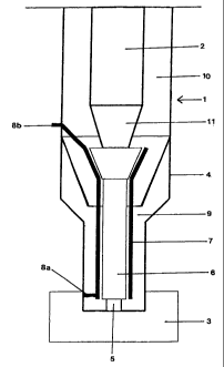
The drawing shows a schematic cross sectional representation of the refractory
nozzle of
the invention. Above the nozzle I a crucible containing a steel melt is an-
anged, from which
molten steel runs through the flow passage 2 out into a melt crucible 3
arranged below the
nozzle. The nozzle is surrounded by a steel housing 4, which has an opening 5
on its lower end,


CA 02387375 2002-05-22
4

the diameter of the opening being at least as large as the diameter of the
lower part 6 of the
nozzle. The lower part 6 of the nozzle is made of zirconium dioxide. It has an
inner diameter of
about 13 to 16 mm. The lower part 6 is laterally surrounded by a heater 7 with
connections 8a,
8b. Between heater 7 and housing 4 a thermally highly insulating material 9 is
ananged, in order
to avoid a loss of heat toward the outside.

The material of the upper part 10 is, for example, aluminum oxide. The flow
passage 2
has a diameter in the area of the upper part 10, which is larger by about 30
to 40 mm than the
diameter of the lower part 6. The flow passage 2 tapers conically toward the
lower part in a
transition region 11.

-o The closure of the nozzle at its upper end can take place by stopper rods
or slides,
wherein these either close the nozzle completely or open it completely, so
that the above
described disadvantages due to partial opening and the consequently resulting
regulation are
dispensed with in the arrangement of the invention.

Representative Drawing
A single figure which represents the drawing illustrating the invention.
Administrative Status

For a clearer understanding of the status of the application/patent presented on this page, the site Disclaimer , as well as the definitions for Patent , Administrative Status , Maintenance Fee  and Payment History  should be consulted.

Administrative Status

Title Date
Forecasted Issue Date 2009-07-21
(22) Filed 2002-05-22
(41) Open to Public Inspection 2003-01-13
Examination Requested 2004-09-09
(45) Issued 2009-07-21
Deemed Expired 2015-05-22

Abandonment History

There is no abandonment history.

Payment History

Fee Type Anniversary Year Due Date Amount Paid Paid Date
Application Fee $300.00 2002-05-22
Registration of a document - section 124 $100.00 2002-07-18
Maintenance Fee - Application - New Act 2 2004-05-24 $100.00 2004-04-16
Request for Examination $800.00 2004-09-09
Maintenance Fee - Application - New Act 3 2005-05-23 $100.00 2005-05-03
Maintenance Fee - Application - New Act 4 2006-05-22 $100.00 2006-04-13
Maintenance Fee - Application - New Act 5 2007-05-22 $200.00 2007-04-12
Maintenance Fee - Application - New Act 6 2008-05-22 $200.00 2008-04-14
Maintenance Fee - Application - New Act 7 2009-05-22 $200.00 2009-04-16
Final Fee $300.00 2009-04-29
Maintenance Fee - Patent - New Act 8 2010-05-24 $200.00 2010-05-07
Maintenance Fee - Patent - New Act 9 2011-05-23 $200.00 2011-05-05
Maintenance Fee - Patent - New Act 10 2012-05-22 $250.00 2012-05-11
Registration of a document - section 124 $100.00 2012-07-11
Maintenance Fee - Patent - New Act 11 2013-05-22 $250.00 2013-05-08
Owners on Record

Note: Records showing the ownership history in alphabetical order.

Current Owners on Record
RHI AG
Past Owners on Record
HALLAM, CHRIS
HERAEUS ELECTRO-NITE INTERNATIONAL N.V.
KENDALL, MARTIN
Past Owners that do not appear in the "Owners on Record" listing will appear in other documentation within the application.
Documents

To view selected files, please enter reCAPTCHA code :


To view images, click a link in the Document Description column. To download the documents, select one or more checkboxes in the first column and then click the "Download Selected in PDF format (Zip Archive)" or the "Download Selected as Single PDF" button.

List of published and non-published patent-specific documents on the CPD .

If you have any difficulty accessing content, you can call the Client Service Centre at 1-866-997-1936 or send them an e-mail at CIPO Client Service Centre.


Document
Description 
Date
(yyyy-mm-dd) 
Number of pages   Size of Image (KB) 
Abstract 2002-05-22 1 21
Description 2002-05-22 4 165
Representative Drawing 2002-10-07 1 4
Cover Page 2002-12-20 1 36
Claims 2002-05-22 2 63
Drawings 2002-05-22 1 12
Claims 2008-10-15 1 50
Representative Drawing 2009-06-22 1 5
Cover Page 2009-06-22 2 39
Prosecution-Amendment 2004-09-09 1 27
Correspondence 2002-07-04 1 23
Assignment 2002-05-22 2 74
Assignment 2002-07-18 2 73
Prosecution-Amendment 2004-10-25 1 37
Prosecution-Amendment 2008-04-15 3 80
Prosecution-Amendment 2008-10-15 3 128
Correspondence 2009-04-29 1 28
Assignment 2012-07-11 5 115