Note: Descriptions are shown in the official language in which they were submitted.
CA 02387694 2002-05-28
- 1 -
METHOD OF PRODUCING REDUCED METALS
AND
APPARATUS FOR REDUCING METAL OXIDES
BACKGROUND OF THE INVENTION
1. Field of the Invention
The present invention relates to a method suitably used
for producing reduced metals, such as reduced iron and the
like, by heating a metal oxide, such as iron oxide or the
like, together with a reducing agent in a combustion furnace,
and also to an apparatus for reducing metal oxides.
2. Description of the Related Art
In order to produce reduced iron, i.e., metallic iron,
a method is known in which iron oxide is reduced by being
heated together with carbonaceous material in a furnace.
The furnace known as being used in this case is an electric
furnace in which heating is performed by means of electrical
energy, and a combustion furnace in which heating is
performed by means of combustion heat evolved from fuel.
For example, a method designed to use a combustion
furnace is known as disclosed in Japanese Unexamined Patent
Application Publication No. 11-061216 and so on. In this
method, agglomerates obtained from iron oxide and
carbonaceous material, i.e., iron oxide pellets filled with
carbonaceous material, are heated by a burner in a rotary
CA 02387694 2002-05-28
- 2 -
hearth furnace, whereby reduced iron is produced. Of the
accompanying drawings, FIG. 3 shows, as a schematic view, an
apparatus taken up in explaining the production method of
reduced iron using the rotary hearth furnace noted above.
This apparatus is equipped with a rotary hearth furnace 1
that is constituted of a ring-shaped rotary hearth 2 and a
furnace body 3 mounted to cover the rotary hearth 2. By
driving means (not shown), the rotary hearth 2 can rotate,
i.e., revolve, at appropriate speeds. Carbonaceous
material-filled iron oxide pellets 7 are supplied to the
rotary hearth furnace 1 through a feed hopper 5 for
feedstock charge disposed in the furnace so that they are
placed on the rotary hearth 2 and then heated and reduced
while the rotary hearth is being traveled in the direction
of rotation in the furnace. The pellets 7 thus reduced are
taken out of the furnace by discharge means 8 located
downstream in the direction of rotation. In the apparatus
shown here, such discharge means are structured to be belt
conveyor-type discharge means.
In the rotary hearth furnace 1, a plurality of burners
4 are employed as heating means that are positioned on the
inner wall surface of the furnace body 3 and along the
direction of rotation. Thus, the pellets 7 can be
substantially uniformly heated in the furnace. Exhaust gas,
i.e., combustion gas, evolved by burner heating is exhausted
CA 02387694 2002-05-28
- 3 -
via an exhaust gas line 6 arranged at a proper portion of
the furnace body 3. Subsequently, the exhaust gas is
subjected to heat removal by a waste heat-recovery unit (not
shown), such as a heat exchanger or the like, followed by
temperature control using a temperature control unit and
then by dust removal using a bag filter. The exhaust gas
after being so treated is released in the air.
However, when iron oxide is reduced by burner heating
as mentioned above, general-purpose fuel such as
commercially available gas, heavy oil, pulverized coal or
the like must be used in large amounts. Namely, mass
consumption of combustion heat evolved from the general-
purpose fuel is necessary, and as a result, is responsible
for poor cost performance.
On the other hand, a method in which organic matter is
carbonized by heating is known as disclosed in Japanese
Unexamined Patent Application Publication No. 2001-3062. In
this method, dry-distilled gas generated while organic
matter is being heated is utilized as fuel for a burner used
to heat the organic matter. Another method is known as
shown in FIG. 4. In the method of FIG. 4, an externally
heated kiln 10 is used as a carbonization furnace, and
feedstock to be carbonized, i.e., organic matter, is put
into the carbonization furnace, i.e., the kiln. After dry-
distilled gas generated from the carbonization feedstock is
CA 02387694 2002-05-28
- 4 -
allowed to burn in a combustion furnace, part of the
resulting combustion gas is released outside via a
temperature control tower and a bag filter, while the
remaining gas is supplied to a heat exchanger 11 disposed in
the carbonization furnace 10 so that this gas is utilized to
heat the carbonization feedstock. However, the amount of
heat generated by combustion of the dry-distilled gas is
larger than that needed for carbonizing the organic matter.
For this reason, the amount of heat having been generated
cannot be wholly utilized to advantage and is partly wasted.
Japanese Unexamined Patent Application Publication No.
2000-309780 discloses a method in which large amounts of
heat are supplied to a waste material such that the latter
is caused to undergo dry distillation and thermal
decomposition, and the resulting thermal decomposition solid
products and gaseous products are reused, respectively, as
fuel. However, the above publication fails to disclose how
these solid and gaseous decomposition products are utilized.
The publication also discloses using kilns in two stages
with a view to avoiding the formation of carbonaceous solid
products and gaseous products such as hydrogen, lower
hydrocarbons and the like. In such an instance, equipment
and facilities are so complicated as to present low cost
performance. Moreover, the content of carbonaceous solid
products is small so that the resulting thermal
,: -
CA 02387694 2002-05-28
-
decomposition solids are difficult to be used as reducing
agents.
SUMMARY OF THE INVENTION
The present inventors have conducted extensive research
in solving the above-mentioned problems of the conventional
art. As a result of this research, it has been found that
when a carbonization furnace and a reduction furnace are
combined together, reduced metals can be produced with a
sharp cut in production cost. More specifically, it has
been found that when dry-distilled gas generated during
carbonization of organic matter is used as fuel for burner
heating in metal reduction, the consumption of general-
purpose fuel, such as commercially available gas, heavy oil,
pulverized coal or the like, can be greatly saved. This
saving in the consumption of general-purpose fuel appears to
be attributed to the fact that the metal reduction requires
much heat unlike the carbonization of organic matter.
Namely, it has been found that when both carbonization
equipment and metal reduction equipment are considered as a
whole, the overall thermal efficiency can be enhanced with
consequential considerable cutting in the production cost of
a reduced metal.
With regard to the case where a carbonization furnace
and a reduction furnace are used as combined, it has also
CA 02387694 2002-05-28 r+r~n"`..
- 6 -
been found that when a metal oxide is placed in advance in
the carbonization furnace, a heat medium such as sand or the
like, usually employed in the latter furnace is not: required
so that no sand separation is needed. Nor are extra process
steps necessary for mixing carbonaceous matter and a metal
oxide. Hence, feedstock such as a metal oxide, a reducing
agent and the like can be prepared with good efficiency, and
when both carbonization equipment and metal reduction
equipment are considered as a whole, the production cost of
a reduced metal can be markedly cut down.
The present invention has been completed based on the
foregoing findings.
Accordingly, one object of the present invention is to
provide a method of producing reduced metals, which can
yield excellent cost performance, and an apparatus for
reducing metals oxides.
Another object of the invention is to provide a method
of producing reduced metals, such as reduced iron, etc.,
which can yield excellent thermal efficiency and minimum
consumption of combustion heat from general-purpose fuel,
and an apparatus for reducing metals oxides.
Yet another object of the invention is to provide a
method of producing reduced metals, which can prepare
feedstock, such as metal oxides, reducing agents and the
like, with good efficiency, and an apparatus for reducing
I :L: . . . .. . .
CA 02387694 2002-05-28
- 7 -
metals oxides.
According to one aspect of the present invention, a
method of producing reduced metals from metal oxides is
provided which comprises the step of: heating a mixture
comprising a metal oxide and a reducing agent'by means of a
burner, thereby reducing the metal oxide to a reduced metal;
wherein dry-distilled gas generated during carbonization of
an organic matter-containing component, such as town waste
or industrial waste, or solid fuel obtained by treatment
thereof, is used as fuel for the burner.
Preferably, in this method, the sensible heat of
exhaust gas evolved by the burner is used as heat for
carbonizing the organic matter-containing component. Also
preferably, carbide derived by carbonizing the organic
matter-containing component is used as the reducing agent.
According to another aspect of the present invention, a
method of producing reduced metals from metal oxides
comprises the steps of: carbonizing an organic matter-
containing component to prepare a carbide; and heating a
mixture comprising a metal oxide and the carbide, thereby
reducing said metal oxide to a reduced metal; wherein said
metal oxide is fed together with said organic matter-
containing component to carbonization furnace as heat media.
Furthermore, in this method, a metal oxide is caused to
coexist as a heat medium when the organic matter-containing
CA 02387694 2007-01-05
- 8 -
component is carbonized in a carbonization furnace, and a
mixture of carbide taken out of the carbonization furnace and
an organic matter-containing component is reduced in a
reduction furnace.
According yet to another aspect of the invention, an
apparatus for reducing metal oxides is provided which
comprises: a carbonization furnace for carbonizing an organic
matter-containing component, thereby generating dry-distilled
gas; a reduction furnace, such as a movable hearth furnace,
for heating a mixture comprising a metal oxide and a reducing
agent by means of a burner, thereby reducing the metal oxide;
and a line for supplying the dry-distilled gas to the burner
as fuel therefor from the carbonization furnace.
Preferably, in this apparatus, a line for exhausting
combustion gas generated by the burner is connected to the
carbonization furnace for heat exchange to be performed. Also
preferably, a line for supplying carbide taken out of the
carbonization furnace is connected to the reduction furnace.
In another aspect, the present invention provides a
method of producing reduced metals comprising: heating in a
movable hearth furnace a mixture comprising a metal oxide and
a reducing agent by means of a burner, thereby reducing said
metal oxide to a reduced metal; wherein dry-distilled gas
generated during carbonization of an organic matter-containing
component is used as fuel for said burner; and wherein the
CA 02387694 2007-01-05
- 8a -
sensible heat of exhaust gas evolved by said burner is used as
heat for carbonizing said organic matter-containing component.
In another aspect, the present invention provides a
method of producing reduced metals from metal oxides
comprising the steps of: carbonizing an organic matter-
containing component to prepare a carbide; and heating in a
movable hearth furnace a mixture comprising a metal oxide and
the carbide, thereby reducing said metal oxide to a reduced
metal; wherein said metal oxide is fed together with said
organic matter-containing component to carbonization furnace
as heat media.
In another aspect, the present invention provides an
apparatus for reducing metal oxides comprising: a
carbonization furnace for carbonizing an organic matter-
containing component, thereby generating dry-distilled gas; a
movable hearth furnace for heating a mixture comprising a
metal oxide and a reducing agent by means of a burner, thereby
reducing said metal oxide; and a line for supplying said dry-
distilled gas from said carbonization furnace to said burner.
BRIEF DESCRIPTION OF THE DRAWINGS
FIG. 1 is a schematic view showing one preferred
embodiment of the apparatus for reducing metal oxides
according to the present invention.
CA 02387694 2002-05-28
- 9 -
FIG. 2 is a schematic view showing another preferred
embodiment of the apparatus for reducing metal oxides
according to the invention.
FIG. 3 is a schematic view showing a conventional
reduction furnace.
FIG. 4 is a schematic view showing a conventional
carbonization furnace.
DESCRIPTION OF THE PREFERRED EMBODIMENTS
The present invention will now be described in greater
detail with reference to the attached drawings. It should
be understood that the invention is not limited to the
structures and functions shown in these drawings, but
various changes and modifications may be made within the
scope of what has been and will be disclosed earlier and
later. All such changes and modifications are to be
included within the spirit and scope of the appended claims.
In the drawings, like reference numerals denote like parts
in order to avoid duplication.
FIG. 1 is a schematic representation of one preferred
embodiment of the apparatus according to the present
invention. This apparatus comprises a carbonization furnace
for carbonizing an organic matter-containing component, a
rotary kiln in this embodiment, and a reduction furnace 1
for reducing a metal oxide, a rotary hearth furnace in this
CA 02387694 2002-05-28
- 10 -
embodiment.
The carbonization furnace 10 is provided with a feed
opening 16a for charging an organic matter-containing
component, and heating means (not shown). Here, the heating
means include combustion type heating means such as a burner
and the like, and electrical heating means such as a heater,
etc. The organic matter-containing component having been
charged from the feed opening 16a is heated, i.e., dry-
distilled, for example, at 300 to 800 C to derive carbide.
In order to improve heating efficiency, a conventional heat
medium such as sand or the like are in most cases introduced
together with the organic matter-containing component into
the carbonization furnace 10. Dry-distilled gas generated
by heating, i.e., dry distillation, is transported through a
dry-distilled gas line 12 connected to the carbonization
furnace 10. A gas holder may be located midway the dry-
distilled gas line 12 for the dry-distilled gas to be
temporarily stored, and the dry-distilled gas may be cooled
to some extent.
On the other hand, the reduction furnace 1 is provided
with a rotary hearth 2; a furnace body 3 for covering the
hearth 2; a feed hopper 5 for charging feedstock in the
furnace 1, which feedstock are agglomerates of a metal oxide
such as iron oxide, etc., and a reducing agent such as a
carbonaceous reducing agent or the like; burners 4 for
r_.
CA 02387694 2002-05-28
heating the feedstock with the combustion heat of fuel, for
example, at 1,000 to 1,500 C; discharge means 8 for
discharging a metal reduced by heating, such as reduced iron
or the like; and an exhaust gas line 6 for releasing exhaust
gas, i.e., combustion gas, evolved by the burner. The
reduction furnace 1 thus structured is identical to the
known reduction furnace 1 already stated earlier.
In the present invention, each burner 4 is connected to
a supply line for general-purpose fuel such as commercially
available gas, heavy oil, pulverized coal or the like, and
further to a dry-distilled gas line 12 for transporting dry-
distilled gas in part or wholly to the burner 4, which gas
has been taken out of the carbonization furnace 10. In this
embodiment, the gas is wholly transported. Hence, the dry-
distilled gas can be used as fuel for the burner, and this
brings a large saving in the amount of general-purpose fuel
such as commercially available gas, heavy oil, pulverized
coal or the like. Moreover, since much heat is often
accumulated as sensible heat in the above-mentioned dry-
distilled gas, the thermal efficiency in the system can
sometimes be further improved by supplying the sensible heat
through the burner 4 to the rotary hearth furnace 1. In
this instance, much more saving can be obtained as to the
amount of general-purpose fuel used. Here, the dry-
distilled gas and general-purpose fuel are used as combined
CA 02387694 2002-05-28
- 12 -
so that even when the amount and quality of the dry-
distilled gas are varied, heating can be controlled by
adjusting the amount and so on of general-purpose fuel.
This structure is also suitable for treating an organic
matter-containing component, for example, a waste material
to be described later, that is easily variable in character.
The dry-distilled gas and general-purpose fuel do not need
to be supplied to the same burner, but may be supplied
separately to their respective different burners.
If only the dry-distilled gas is used as fuel for the
reduction furnace 1, the thermal efficiency in the system
can be enhanced, as described above, with considerable
saving in the consumption of general-purpose fuel. It is
desired, however, that the sensible heat of exhaust gas
evolved from the reduction furnace 1 be also utilized as
viewed in FIG. 1. Namely, the exhaust gas evolved from fuel
that has been burnt by the burner is partly or wholly
transported toward the carbonization furnace 10 through a
heating line 13, i.e., a second exhaust gas line, which
heating line is arranged to diverge from the exhaust gas
line 6. In the embodiment of FIG. 1, the exhaust gas is
shown partly transported. The exhaust gas is supplied to a
heat exchanger 11 located in the carbonization furnace 10
for the organic matter-containing component to be heated.
This permits effective use of the exhaust gas having come
;i .
CA 02387694 2002-05-28
- 13 -
from the reduction furnace, and therefore, further enhances
the thermal efficiency.
Alternatively, the sensible heat of exhaust gas having
been returned from the reduction furnace can be utilized in
a second heat exchanger other than the heat exchanger 11
mentioned above. Namely, the exhaust gas is first
transported to the second heat exchanger where sub- fluids
such as air, water vapor and the like are heated, and
thereafter, the heated fluid is supplied to the heat
exchanger 11 of the carbonization furnace where the same is
used as a heat source. After being used to heat the
carbonization furnace, the fluid may be again heated in the
second heat exchanger and reused as a heat source for the
carbonization furnace. When the sub-fluid noted above is
air, the air having been utilized to heat the carbonization
furnace may be used as combustion air that is, for example,
air to be supplied together with the above-mentioned fuel to
the burner 4 of the reduction furnace. When the sub-fluid
is water vapor, a boiler may be used as the heat exchanger.
In the case where the second heat exchanger is used, the
carbonization furnace can be prevented from being damaged
because clean fluid, but not the exhaust gas having been
extracted from the reduction furnace, is supplied to the
carbonization furnace, i.e., the heat exchanger 11 of the
latter furnace.
CA 02387694 2002-05-28
- 14 -
Exhaust gas having not been supplied to the
carbonization furnace 10 is released in the air via a
temperature control tower and a bag filter. On the other
hand, the exhaust gas having been utilized as a heat source
for the carbonization furnace 10 is mixed with the exhaust
gas having not been supplied to the carbonization furnace 10
in the above temperature control tower and then passed
through the bag filter and released in the air. To treat
the exhaust gas having been supplied to the carbonization
furnace 10 and the exhaust gas having not been supplied to
this furnace, it is not necessarily required that the same
temperature control tower and bag filter be employed, but
this treatment may be effected using different temperature
control towers and bag filters.
When the sensible heat of exhaust gas is not utilized
as a heat source for the carbonization furnace, the exhaust
gas may be cooled, for example, with a scrubber.
The organic matter-containing component used as
feedstock for the carbonization furnace 10 is not
particularly restricted so long as the same is carbonized
upon heating, i.e., dry distillation, to evolve dry-
distilled gas. Wood, resin and volatile matter-rich coal
and the like can be used as organic matter-containing
components. Suitable organic matter-containing components
are chosen from waste and solid fuel obtained by treatment
CA 02387694 2002-05-28
- 15 -
thereof (refuse-derived fuel or RDF). The waste includes
combustible trash, such as kitchen refuse, paper, plastic
and the like, disposed of by households, and industrial
waste, such as waste plastics, waste tires, waste wood,
shredded dust, etc., disposed of by industrial sectors. The
waste has today been in the face of much difficulty in
disposal and treatment. Thus, pollution burdens on the
environment can be eased by the use of the waste as
feedstock for the carbonization furnace 10.
On the other hand, a metal oxide such as iron oxide or
the like, and a reducing agent such as a carbonaceous
reducing agent or the like may be used in a mixture as
feedstock for the reduction furnace 1. Agglomerates are
rather preferred which are obtained by agglomerating such a
mixture. The use of the agglomerates is to reduce the metal
oxide with good efficiently. The agglomerates can be
reduced while they are maintained as mixed, or after they
are somewhat melted to such an extent that a film, i.e., an
outer skin, is formed on the surfaces of the agglomerates.
Reduction that can be followed in forming the outer skin of
the reduced metal is one disclosed, for example, in Japanese
Unexamined Patent Application Publication No. 9-256017. in
the method of this publication, a metal oxide such as iron
oxide or the like is reduced using reductive gas, i.e., CO
gas, which is generated from a reducing agent contained in
CA 02387694 2002-05-28
*+~.
- 16 -
agglomerates when the latter are heated. More specifically,
a reduced metal produced in an initial course of reduction
with heating is caused to bond diffusively to the
agglomerates and to form an outer skin of the reduced metal.
Then, the concentration of the CO gas entrapped inside this
outer skin is increased to internally reduce the metal oxide.
The reduced metal, which has been internally formed, grows
while it adheres successively to the inner surface of the
outer skin mentioned above. According to the method of the
above publication, a reduced metal such as reduced iron or
the like can be produced with high purity.
No particular restriction is imposed on the shape of
the agglomerate if the latter has a reducing agent loaded
internally, i.e., filled therein. Various shapes may be
used which include a lump, a granule, a briquette, a pellet,
a rod and the like.
To agglomerate a metal oxide and a reducing agent, a
powdery metal oxide and a powdery reducing agent are in most
cases mixed with a powdery binder such as bentonite or the
like, followed by agglomeration with suitable agglomerating
means such as a press or the like.
As the above-mentioned reducing agent, materials such
as coal, coke, char and the like, particularly powders
thereof, or fine coke, i.e., coke breeze, may be used which
are in common use in reducing metal oxides such as iron
I yb. ,. . . s..
CA 02387694 2002-05-28
- 17 -
oxide and the like. It is desired that, rather than these
materials, carbide be used which is obtained when the above-
mentioned organic matter-containing component is carbonized
in the carbonization furnace 10. When the carbide is used,
all of the discharges from the carbonization furnace 10,
i.e., dry-distilled gas and carbide, can be used in the
reduction furnace 1 such as a rotary hearth furnace or the
like, and equipment efficiency can be further enhanced. The
carbide noted here has hitherto been applied only as a
material for road beds, etc. When the carbide is utilized
as the reducing agent, the amounts of conventional reducing
agents can be saved with eventual cut in production cost.
In particular, although expensive coke breeze has been
generally frequently used as the reducing agent, the present
invention is effective in saving the amount of coke breeze
and hence in cutting the production cost considerably.
To produce carbide in the carbonization furnace 10, a
heat medium such as sand or the like is sometimes used as
previously stated. Preferably, the sand should be left
removed when the resulting carbide is used as a reducing
agent for the reduction furnace 1.
In the case where the carbide is used as a reducing
agent for the reduction furnace 1, a metal oxide such as
iron oxide or the like may be used as a heat medium for the
carbonization furnace 10. The use of a metal oxide as the
CA 02387694 2002-05-28
- 18 -
heat medium permits the above carbide to be used as
feedstock for the reduction furnace 1 with no need for
removal of the heat medium. Moreover, tar having developed
in the carbonization furnace is taken outside therefrom
together with the metal oxide, and hence, this furnace can
be protected from becoming deposited with the tar. In
addition, the metal oxide and carbide are already mixed with
each other in the carbonization furnace 10 so that no extra
process steps are required for mixing these two materials.
The metal oxide and organic matter-containing component may
be put, after being premixed, or individually without mixing,
into the carbonization furnace. The metal oxide having
entered the carbonization furnace is charged along with the
above carbide into the reduction furnace 1 where the same
undergoes reduction. In this instance, when needed, other
metal oxides and/or other reducing agents may be placed in
the reduction furnace 1.
In the case where, simultaneously with use of the
carbide from the carbonization furnace 10 as the reducing
agent for the reduction furnace 1, the metal oxide such as
iron oxide or the like is used as a heat medium for the
carbonization furnace 10, this alone can cut the production
cost of the resultant reduced metal. Hence, the reduction
furnace 1 may be heated only with general-purpose fuel since
the utilization of dry-distilled gas, i.e.,= the heating of
CA 02387694 2002-05-28
- 19 -
the reduction furnace 1 by dry-distilled gas, is not
necessarily required.
The carbide and metal oxide from the carbonization
furnace 10 should preferably be hot-agglomerated although
cold agglomeration is also acceptable. Hot agglomeration
makes highly sticky the tar contained in the carbide, thus
enabling the tar to be used as a bonding agent, i.e., a
binder. This can omit the use of conventional binders such
as bentonite and the like, or save the amount of the same
even when used.
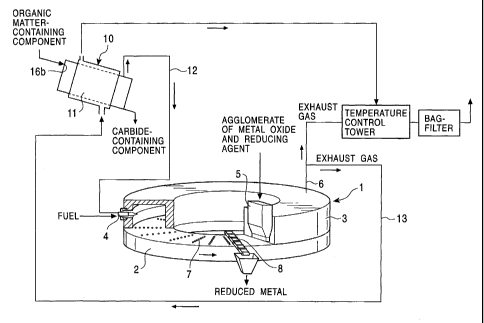
FIG. 2 shows, as a schematic view, a modified
embodiment of the apparatus illustrated in FIG. 1. This
modification is different from the apparatus of FIG. 1 in
the following respects; that is, (a) the carbide obtained in
the carbonization furnace 10 is used as a reducing agent,
(b) the metal oxide is put into the carbonization furnace 10,
and (c) the carbide and metal oxide from the carbonization
furnace 10 are caused to agglomerate.
Namely, the apparatus of FIG. 2 is distinguishable from
the apparatus of FIG. 1 with regard to the facts that (a) a
line 14 is arranged for transporting solid discharges from a
carbonization furnace 10, i.e., carbide and a metal oxide in
this embodiment, to a reduction furnace 1, (b) a feed
opening 16b of the carbonization furnace 10 is so provided
as to charge an organic matter-containing component as well
CA 02387694 2002-05-28
- 20 -
as an metal oxide, and (c) agglomerating means 15, i.e.,
briquetting presses in this embodiment, are disposed midway
the line 14 for agglomerating the above-mentioned solid
discharges. The remaining structural details are common to
those of FIG. 1.
With the apparatus of FIG. 2, a metal oxide is mixed
with an organic matter-containing component while the latter
component is being carbonized in the carbonization furnace
10. After being agglomerated by the agglomerating means 15,
this mixture is supplied via the line 14 to the reduction
furnace 1 where the metal oxide is reduced to a reduced
metal.
As the agglomerating means, briquetting presses such as
a cylinder press, a roll press, a ring-roller press and the
like are used because organic matter can be easily
agglomerated by being softened and compressed. In addition
to these presses, various known machines chosen from
extrusion molders, tumbling granulators such as a pan
pelletizer, a drum pelletizer and the like may be used as
the agglomerating means.
All of the above modifications (a) to (c) do not need
to be carried out with respect to the apparatus of FIG. 1.
Any of (a) the feed opening 16b, (b) the line 14 and (c) the
agglomerating means 15 may be omitted, where desired,
depending on locations to be modified.
CA 02387694 2002-05-28
r~n
- 21 -
in the apparatus of FIG. 1 and FIG. 2, a dechlorination
unit for chloric gas and/or a desulfurization unit may be
attached to the dry-distilled gas line 12 although no such
units are usually needed. That is to say, in the reduction
furnace as employed in FIG. 1 and FIG. 2, i.e., the furnace
where agglomerates of a metal oxide and a reducing agent are
reduced with heating by a burner, such as a rotary hearth
furnace or the like, chloric gas such as chlorine, hydrogen
chloride or the like, and sulfur oxide are frequently
contained in exhaust gas even when the reduction furnaces is
allowed to operate separately and as not combined with the
carbonization furnace 10. Since the exhaust gas system is
by nature greatly durable with respect to chloric gas and
sulfur oxide, it is not generally necessary that a
dechlorination unit and a desulfurization unit be attached
to the dry-distilled gas line even when dry-distilled gas is
used together with the carbonization furnace 10. For
example, if the concentration of chloric gas, particularly
hydrogen chloride, in the exhaust gas is not more than 2,000
ppm by volume, preferably not more than 1,500 ppm by volume,
more preferably not more than 1,000 ppm by volume, no
dechlorination is required for the removal of chloric gas.
However, the amounts of chloric gas and sulfur oxide
become large in dry-distilled gas in some cases depending on
the kind of organic matter-containing components. For
1=M1; ~ , ..,. .
CA 02387694 2002-05-28
- 22 -
example, when a chlorine-containing resin such as polyvinyl
chloride, polyvinylidene chloride or the like is used as an
organic matter-containing component, the resultant dry-
distilled gas reveals a high concentration of chloric gas.
In such an instance, it is desired that due to the
likelihood of the exhaust gas system of becoming corroded, a
dechlorination unit for chloric gas and a desulfurization
unit be attached to the dry-distilled gas line 12.
As the dechlorination unit for chloric gas and the
desulfurization unit, conventional elimination units may be
used which are irrespective of a dry or wet system. For
example, an eliminator using alkalis such as lime, slaked
lime, soda, etc., and an eliminator using active charcoal
may be used. Suitable units include a dry eliminator using
slaked lime and/or active charcoal, a wet eliminator using
slaked lime, and an eliminator capable of selectively
removing chloric gas.
In the dry eliminator in which slaked lime and/or
active charcoal are used, chloric gas and sulfur oxide can
be eliminated, for example, by bringing slaked lime and/or
active charcoal into contact with dry-distilled gas, e.g.,
by blowing slaked lime and/or active charcoal into dry-
distilled gas, thereby entrapping chloric gas and sulfur
oxide through adsorption or fixing in the slaked lime and/or
active charcoal, and then by removing the slaked lime and/or
CA 02387694 2002-05-28
- 23 -
active charcoal by a dust-removing unit.
In the wet eliminator in which slaked lime is used,
chloric gas and sulfur oxide can be eliminated by bringing
slaked lime slurry into contact with dry-distilled gas, e.g.,
in a desulfurization tower.
In the case of selective removal of chloric gas,
chloric gas is selectively eliminated, for example, by
passing dry-distilled gas through a chloric gas-removing
tower. Dry-distilled gas, from which chloric gas has been
removed, is passed through a neutralization tank to remove
sulfur oxide and then supplied to the reduction furnace. On
the other hand, the chloric gas thus subjected to selective
removal is recovered as hydrochloric acid.
Particularly preferred eliminators include an
eliminator that removes chloric gas selectively. With this
eliminator, chloric gas present as a harmful component in
the dry-distilled gas is recoverable as hydrochloric acid
that is of commercial value.
The carbonization furnace for use in the present
invention is not limited to the kiln noted earlier so long
as dry-distilled gas can be evolved, and therefore, various
known furnaces may be used. Suitable furnaces are selected
from among a furnace in which an organic matter-containing
component is heated together with a heat medium, e.g., a
furnace in which an organic matter-containing component and
,;,,, . .. .
CA 02387694 2002-05-28
- 24 -
a heat medium are heated while being mixed during rotation
of the furnace body, such as a rotary kiln or the like, a
furnace in which an organic matter-containing component and
a heat medium are heated by hot air that is supplied from
the bottom, such as a fluidized bed furnace or the like, and
a furnace in which an organic matter-containing component is
melted with heating in the presence of a heat medium, such
as a melting bath or the like.
Next, the reduction furnace for use in the present
invention is not particularly restricted if metal oxides can
be reduced using dry-distilled gas as fuel, and therefore,
various known furnaces may be used. In addition, organic
matter-containing components and reducing agents to be used
in this reduction furnace do not need to be necessarily in
agglomerated form.
Suitable reduction furnaces are a furnace that is
adequate for reducing agglomerates of a metal oxide and a
reducing agent, particularly a furnace that is adequate for
heating the above agglomerate by a burner to thereby form an
outer skin of a reduced metal on the surfaces of the
agglomerates and to further reduce the metal oxide existing
within the agglomerates. Using these furnaces, the reduced
metal can be obtained with high purity.
The suitable reduction furnaces described above include
a furnace that can reduce agglomerates without degradation
. .:.: .. ~ . . ..
CA 02387694 2002-05-28
- 25 -
of their shapes, for example, those disclosed in Japanese
Unexamined Patent Application Publications No. 10-102114,
10-102115, No. 10-102116, No. 10-102117 and No. 10-102118, a
movable hearth furnace such as a rotary hearth furnace, etc.
The present invention will now be described in specific
terms by way of the following examples. The invention
should not be considered to be limited to these examples,
but various changes and modifications may be made within the
scope of what has been and will be disclosed earlier and
later. All such changes and modifications are to be
included within the spirit and scope of the appended claims.
Example 1
Using the apparatus shown in FIG. 2, 700 kg of steel
mill waste to be produced into iron and 400 kg of waste wood
were put into a carbonization furnace 10 from a feed opening
16b. The resulting carbide and steel mill waste mixture was
agglomerated with presses 15, and the agglomerates were
supplied to a rotary hearth-type reduction furnace 1. Dry-
distilled gas from the carbonization furnace 10 and general-
purpose fuel, i.e., natural gas, were mixed with air at a
burner 4. In the reduction furnace 1, the mixed fuel was
caused to burn to heat the above agglomerates, thereby
reducing the steel mill waste. Part of the exhaust gas from
the reduction furnace 1, i.e., the gas designated as
"Exhaust gas A" in Table 1 below, was supplied to the
I .,~.... . ; . ,. .. . .
CA 02387694 2002-05-28
.~;
- 26 -
carbonization furnace for utilization as a heat source
therefor, whereas the remaining gas, i.e., the gas
designated as "Exhaust gas a" in Table 1, was heat-exchanged,
i.e., cooled, and utilized to preheat air to be supplied to
the burner 4. The exhaust gas having been utilized as a
heat source in the carbonization furnace 10, i.e., the gas
designated as "Exhaust gas a" in Table 1, was mixed, in a
temperature control tower, with the exhaust gas having not
been supplied to the carbonization furnace 10, i.e., the gas
designated as "Exhaust gas B" in Table 1, and then released
in the air via a bag filter.
With regard to the above-mentioned operation, the
amount of dry-distilled gas having been burnt by the burner
4, the amount of general-purpose fuel used and the amount of
preheating air used, as well as the amount of exhaust gas
generated are shown in terms of their respective amounts of
energy in Table 1.
Table 1
Dry-distilled gas (sensible 3.8 GJ
heat and combustion heat)
General- ur ose fuel 3.8 GJ
Preheated air 1.0 GJ
Exhaust gas A (as heat source 4.0 GJ
for carbonization furnace)
Exhaust gas a (after use as 2.0 GJ
heat source)
Exhaust gas B 1.9 GJ
I _I:I ,. , . ~ . , .. .
CA 02387694 2002-05-28
- 27 -
Comparative Example
Using the apparatus of FIG. 3, agglomerates of 700 kg
of steel mill waste to be produced into iron and 100 kg of
coke breeze were put into a reduction furnace 1 from a feed
pocket 5. General-purpose fuel, i.e., natural gas, and
preheated air were mixed at a burner 4. In the reduction
furnace 1, the mixed fuel was caused to burn to heat the
agglomerates, thereby reducing steel mill waste. The amount
of general-purpose fuel used and the amount of preheated air
used, as well as the amount of exhaust gas generated are
shown in terms of their respective amounts of energy in
Table 2 below.
Table 2
General- ur ose fuel 7.6 GJ
Preheated air 1.0 GJ
Exhaust gas B 5.9 GJ
According to the present invention, the amount of
general-purpose fuel used in reducing 700 kg of steel mill
waste can be saved by 3.8 GJ. This is clear from the
results of Table 1 compared to those of Table 2.
As described and shown above, in one embodiment of the
invention in which dry-distilled gas evolved during
carbonization of organic matter is used as fuel for burner
. ;I, . . .e,.. . , .
CA 02387694 2002-05-28
- 28 -
heating that is needed in metal reduction, the potential
heat of dry-distilled gas is effectively utilized. Hence,
the thermal efficiency in the system can be enhanced, and
the consumption of general-purpose fuel can be saved.
In another embodiment of the invention in which a metal
oxide is used as a heat medium for the carbonization furnace,
the carbide and metal oxide from that furnace are usedas
they are as feedstock for the reduction furnace. Hence, a
process step for separating a heat medium in common use,
such as sand, etc., and a process step for mixing a metal
oxide and a reducing agent can be omitted, and feedstock
such as metal oxides, reducing agents, etc., can be prepared
with good efficiency.
Example 2
The apparatus shown in Fig. 2 and an externally heated
kiln as a carbonization furnace 10 were used. A wood chip
and an electric arc furnace dust were used as an organic
matter-containing component and a metal oxide which was a
heat conductor of the carbonization furnace 10, respectively.
The wood chip or a mixture of the wood chip and the electric
arc furnace dust were carbonized for one hour in the
carbonization furnace 10. As a result, the amounts of
remaining tar (effluent) per kilogram of wood chip are shown
in Table 3. The ratios of the wood chip and the electric arc
furnace dust are also shown in Table 3.
. :;I.: . . . , .
CA 02387694 2002-05-28
- 29 -
Table 3
Carbonization Temperature
400 C 600 C 800 C
Chip* only 0.28 kg 0.20 kg 0.18 kg
Chip 2:Dust** 3 0.04 kg 0.09 kg 0.06 kg
Chip 1:Dust 3 0.02 kg 0.13 kg -
*Chip: Wood chip
**Dust: Electric arc furnace dust
As shown in Table 3, the presence of the electric arc
furnace dust makes the remaining tar low. This is because
the electric arc furnace dust adsorbs tar.
Example 3
Furthermore, it is preferable that after a mixture of
an organic matter-containing component and a metal oxide is
carbonized in a carbonization furnace, the carbide obtained
from the carbonization furnace is ground.
In a similar manner as Example 2, a wood chip is
carbonized in the presence of an electric arc furnace dust
(the ratio of the chip to the dust: 2 to 3) for one hour at
temperature shown in Table 4. Carbide obtained from the
carbonization furnace was ground for three minutes at 60 rpm
by using ball-mill since the particle size of the carbide
preferably is 1.0 mm or less in view of agglomeration and
CA 02387694 2002-05-28
- 30 -
reduction reaction. Weight percents of particle having 1.0
mm or less of the particle si=ze are shown in Table 4.
in view of the grind of the carbide, carbonization at
high temperature is preferable. As shown in Table 4, the
carbonization at 400, 600 and 800 C accelerated the grind
efficiency, especially the carbonization at 600 and 800 C is
effective.
Table 4
Carbonization Temperature
400 C 600 C 800 C
Before grind 67.0 wt% 71.3 wt% 74.0 wt%
After grind 90.4 wt% 97.6 wt% 97.3 wt%
As mentioned above though, the particle size is
preferably 1 mm or less for the agglomeration, the
agglomeration is done normally in the case that particles
around 5 mm of particle size are included. In addition, in
the case of the agglomeration by using compression molding,
a variety of particle sizes help to agglomerate.
Example 4
The effect of retention time in a carbonization furnace
(carbonization time) on the carbon content was investigated.
In the same manner as Example 2, a wood chip is
a :. . . ... ., . . .
CA 02387694 2002-05-28
- 31 -
carbonized in the presence of an electric arc furnace dust
(the ratio of the chip to the dust: 2 to 3) at 600 C. After
the carbonization and removing the electric arc furnace dust,
the carbon content of the wood chip was measured. Table 5
shows the results.
Table 5
Carbonization Time (min)
20 40 60 180
Carbon content (wt%) 55.4 63.3 58.5 53.7
Long carbonization time, for example 180 min, decreases
the carbon content because of a preliminary reduction,
whereas the preliminary reduction does not spoil the effect
of the present invention. In view of obtaining carbon as a
reducing agent in the latter reduction furnace,
carbonization in the range of from 20 to 70 minutes is
preferable because the reduction in the reduction furnace is
more efficient. A more preferable range is from 40 to 60
minutes.
The carbonization time is determined by considering the
carbonization temperature because high carbonization
temperature makes a reduction rate of a metal oxide fast as
well as the carbonization rate. More actually, the
I.il:. , .. . . .
CA 02387694 2002-05-28 - 32 -
carbonization temperature and time are decided by
considering equipment costs and running costs.
Consequently, the present invention is effective in
achieving considerable cutting in the production costs of
reduced metals.