Note: Descriptions are shown in the official language in which they were submitted.
CA 02387778 2002-04-17
WO 01/32552 PCT/US00/40927
-1-
ONE-PIECE DISPENSING SYSTEM AND
METHOD FOR MAKING SAME
TECHNICAL FIELD
This invention relates to a system for dispensing a product from a
container. The invention is more particularly related to a system
incorporating a dispensing valve which is especially suitable for use with a
squeeze-type container wherein a product can be discharged from the
container through the valve when the container is squeezed.
BACKGROUND OF THE INVENTION
AND
TECHNICAL PROBLEMS POSED BY THE PRIOR ART
A variety of packages, including dispensing packages or containers,
have been developed for personal care products such as shampoo, lotions,
etc., as well as for other materials. Such containers typically have a neck
defining an open upper end on which is mounted a dispensing closure. One
type of dispensing closure for these kinds of containers typically has a
flexible, pressure-openable, self-sealing, slit-type dispensing valve mounted
in
the closure over the container opening. When the container is squeezed, the
valve slits open, and the fluid contents of the container are discharged
through the open slits of the valve. The valve automatically closes to shut
off fluid flow therethrough upon removal of the increased pressure.
Designs of closures using such valves are illustrated in the U. S.
Patent Nos. 5,409,144, 5,676,289, and 5,033,655. Typically, the closure
includes a body mounted on the container neck to hold the valve over the
container opening.
A lid can be provided for covering the valve during shipping and
when the container is otherwise not in use. See, for example, FIGS. 31-34
of U.S. Patent
CA 02387778 2002-04-17
WO 01/32552 PCT/US00/40927
-2-
No. 5,271,531. Such a lid can be designed to prevent leakage from the
valve under certain conditions. The lid can also keep the valve clean and/or
protect the valve from damage.
A dispensing closure incorporating such a pressure-openable valve
provides advantages not found in other types of dispensing closures. For
example, another common type of dispensing closure has a base defining a
dispensing orifice which is normally occluded by a closed lid having a plug
which enters into, and seals, the orifice. The lid must be lifted open to
permit the product to be dispensed through the closure orifice. The lid must
be manually closed after dispensing the product in order to permit the
container to be carried or moved in any position other than a non-vertical
position. Further, the lid must be closed in order to minimize evaporation or
drying out of the product within the container. Also, the lid must be closed
in order to prevent contaminant ingress.
Other types of dispensing closures include lift-up spouts or rotatable
valve members. These features must be manipulated by the user when it is
desired to open a dispensing passage and must be manipulated by the user
when it is desired to close the dispensing passage.
With the above-discussed conventional types of dispensing closures
that do not incorporate a pressure-openable valve, it may be possible to store
the container with the closure thereon in an inverted position (with the
dispensing closure at the bottom) so as to maintain the container product
near the dispensing passage or orifice. This may be advantageous when the
product is a rather viscous liquid because, when the inverted dispensing
closure is opened, the product is already located at the dispensing passage or
orifice and the dispensing time is minimized.
However, while the inverted storage of such a dispensing closure and
container may speed dispensing of.a viscous product, this can result in
creating a rather messy condition at or around the dispensing closure passage
or orifice. For example, with conventional dispensing closures that have a
CA 02387778 2002-04-17
WO 01/32552 PCT/US00/40927
-3-
lid plug sealingly occluding a dispensing orifice in a closure base, inverted
storage causes the inner end of the lid plug to be coated with the product.
When the lid is opened, the product on the end of the plug is carried with
the plug along the surface of the orifice. Some of the product sticks to the
surface of the orifice and/or adjacent exterior edges of the closure base
around the orifice. Some of the product also sticks to the lid plug. When
the lid is subsequently closed after dispensing the product, the product on
the
lid plug and around the closure base orifice can create a messy condition
around the exterior edge of the dispensing orifice. With the dispensing
closure in the closed condition, the product around the exterior of the
dispensing orifice can dry out and become somewhat hardened or encrusted
during a subsequent period of non-use. This is not only aesthetically
unpleasant, but it can inhibit the easy opening of the lid during subsequent
use.
A pressure-openable dispensing valve advantageously eliminates or
minimizes some of the above-discussed problems. Because such a valve
does not have to be directly manipulated to effect its opening or closing, the
user merely needs to squeeze the container to effect dispensing of the
container product. Although such a simple squeezing action is generally
required for dispensing a product, especially a viscous product, through any
type of dispensing closure, the use of a pressure-openable valve in a
dispensing closure eliminates the need to also initially, manually manipulate
the valve, spout, or lid employed with other types of conventional closures.
Because a closure with a pressure-openable dispensing valve remains
closed unless the container is squeezed, the closure and container can be
inverted for storage (with the dispensing closure and valve at the bottom).
Product does not leak through such a valve, and there is little or no mess on
the exterior of the valve or surrounding closure surfaces.
Further, the use of a pressure-openable valve permits more accurate
control of the dispensing process. Because the pressure-openable valve
CA 02387778 2002-04-17
WO 01/32552 PCT/USOO/40927
-4-
typically has a relatively thin membrane in which the dispensing slots are
defined, there is no long orifice or passage through which the product must
pass prior to discharge from the dispensing closure. Thus, the product
discharges from the dispensing closure through such a pressure-openable
valve relatively quickly and in substantially direct response to squeezing
forces applied to the container which are readily sensed by the user as the
user squeezes the container. The user has a more accurate "feel" of the
relationship between the container squeezing force and the discharging
product as the user squeezes the container.
Further, because the pressure-openable valve membrane defining the
dispensing aperture slits is relatively thin, and because the valve can be
positioned in the dispensing closure at, or very near, the most exterior
surface of the closure, the user can readily observe the valve and its
dispensing slits. Thus, the user can easily see the product being discharged,
and the user can more readily determine how hard to squeeze the container
and when to terminate the squeezing of the container.
While dispensing closures with pressure-openable dispensing valves
function generally satisfactorily in applications for which they are designed,
it would be desirable to provide an improved dispensing system incorporating
such pressure-openable valves. For example, in conventional dispensing
closures incorporating such pressure-openable valves, special retention
systems are required to hold the valves within the closures. In particular, a
pressure-openable valve typically is retained in the closure base by means of
a separate retainer ring which is snap-fit into the closure base over a flange
of the valve. Thus, at least three separate components are typically required
in such a conventional dispensing closure: the closure base (which may or
may not include an auxiliary, hinged lid), the pressure-openable valve, and
the retainer ring.
Such snap-fit rings are small and somewhat flexible. Because the
pressure-openable valve and the retainer ring are both relatively small, it is
CA 02387778 2008-05-02
23158-1804
-5-
difficult to provide a design which facilitates component assembly and proper
snap-fit retention. Careful control of dimensional tolerances is required in
order to insure that the components can be properly assembled and in order
to insure proper engagement of the snap-fit retention features.
During the manufacture of such a dispensing closure, processes must
be employed to manufacture, handle, and assemble (1) the relatively small,
and very flexible, pressure-openable valve, (2) the small, snap-fit retainer
ring, and (3) the closure base. The manufacturing processes include the
following: the manufacture of the three components, the temporary storage of
the three components, the processing of the three components (including
quality control inspections and material handling (including conveying)), and
the assembly of the components.
The above-discussed manufacturing processes are susceptible to
problems. For example, the components can be inadvertently damaged
during the manufacturing operations. The components can also be
inadvertently misaligned during assembly (e.g., resulting in an ineffective,
or
loose, snap-fit retention of the valve within the closure base). This can more
easily occur if the valve is molded from liquid silicone rubber which is soft
and pliable. Such a material is preferred in some types of packaging, and
has proven particularly advantageous since the material is inherently
relatively inert, and will therefore not either adulterate or react with most
products contained within a container. Examples of a commercially available
valve molded from silicone rubber are disclosed in the above-identified U.S.
Patent Nos. 5,409,144, 5,439,143, and 5,676,289.
Although liquid silicone rubber possesses many attributes for use in
packaging, it also has other characteristics which render such applications
problematic. For example, the surfaces of silicone rubber components are
extremely tacky or sticky, having a very high coefficient of friction. As a
result, the proper handling of such components is difficult. For example, in
CA 02387778 2002-04-17
WO 01/32552 PCT/US00/40927
-6-
attempting to attach a silicone rubber dispensing valve to a container by a
conventional snap-fit retainer ring or threaded collar arrangement, the
surfaces of the valve flange may stick to the adjacent surfaces of the
container and a retainer ring or threaded collar before the ring or collar can
be mounted securely enough to create a leak-resistant seal. Tightening of the
threaded collar often causes the valve flange, as well as the entire valve, to
distort from its designed shape, thereby preventing the formation of a secure
seal, and/or changing the intended dispensing and sealing characteristics of
the valve.
Thus, the manufacturing processes--involving separate molding of
three or more components, inspection, handling, and assembly--must be
undertaken with great care which is difficult and expensive to provide.
Notwithstanding the exercise of a high degree of care in the manufacturing
processes, such processes remain a potential source of trouble and can
occasionally result in the manufacture of a defective assembly.
Further, the multi-component dispensing closure employing a pressure-
openable valve is prone to failure after manufacture when subjected to
intentionally or inadvertently applied high impact loads. For example, when
a completed multi-component closure is shipped to a packager for mounting
on a filled container, the packager typically handles the closure with
automatic equipment. A portion of the closure may be snagged by such
equipment, or the closure may be pushed with excessive force against
another object. These actions may lead to a loosening or separation of the
closure assembly components prior to, or during, the mounting of the closure
on the filled container. This can create problems in the packager's automated
filling line and lead to spills and/or shutdowns of the line while the problem
is corrected.
In addition, when the completed package (comprising the filled
container and multi-component dispensing closure mounted thereon) is put
into the distribution channels by the packager, accidental or intentional
loads
CA 02387778 2002-04-17
WO 01/32552 PCT/US00/40927
-7-
imposed on the closure may cause a failure of a part of the closure. If the
package is subjected to excessive impact forces during shipping and/or while
being stored and/or displayed, then damage (e.g., loosening) of the closure
components may occur.
Also, the fact that the conventional closure includes an assembly of
the three components (closure body, valve, and retention ring or collar)
makes it easier for someone to tamper with the closure by partially or
completely separating the closure components. Accordingly, it would be
desirable to provide an improved dispensing system which would eliminate,
or at least minimize, the problems associated with multi-component
dispensing closures.
It would also be desirable to provide an improved dispensing system
for a package which would reduce the number of separate components
needed to produce a completed package.
It would also be beneficial if such an improved dispensing system
could accommodate the use of a variety of different materials.
Further, it would be desirable if such an improved dispensing system
could be provided with a design that would accommodate efficient, high
quality, large volume manufacturing techniques with a reduced product reject
rate.
The present invention provides an improved dispensing system which
can accommodate designs having the above-discussed benefits and features.
SUMMARY OF THE INVENTION
According to one aspect of the present invention, a dispensing system
is provided for a container. The dispensing system is adapted to be sealingly
disposed with respect to, and dispense a product from, a discharge opening
of a dispensing end structure of a container wherein an annular mounting
flange extends radially inwardly adjacent the opening. The product may be a
liquid or other generally flowable substance, such as a granular or
particulate
material or a powder.
CA 02387778 2002-04-17
WO 01/32552 PCT/US00/40927
-8-
The dispensing system includes a dispensing valve molded from at
least one material to define a flexible, resilient structure having a central
head portion, a sleeve extending outwardly from the flexible, central head
portion, and a surrounding marginal portion. The head portion has
intersecting slits that define a normally closed dispensing orifice which
opens
when the pressure in the interior of the container exceeds the pressure on the
exterior of the valve by a predetermined amount. The marginal portion of
the valve is connected with the head portion, and the marginal portion has a
generally annular wall defining a generally tubular groove which is open
radially outwardly for receiving the mounting flange.
The mounting flange may be part of the container. Alternatively, the
mounting flange may be part of a separate closure which is adapted to be
permanently or releasably attached to the container. The generally annular
wall of the valve which defines the annular groove is sufficiently flexible to
temporarily deform as the wall is forced against the mounting flange to
accommodate seating of the mounting flange in the groove. The annular
wall is also sufficiently resilient to accommodate the retention of the
mounting flange in the groove by adjacent portions of the wall.
The groove is defined at a location along the vertical height of the
annular wall to locate the sleeve and head portion within the discharge
opening when the valve head portion is closed while the valve is sealingly
disposed with respect to the discharge opening.
In a preferred embodiment, the valve is molded from a liquid silicone
rubber, and the valve has a dispensing orifice defined by normally closed
slits. Preferably, the valve annular wall includes a generally annular upper
shoulder and a generally annular, lower retention flange. The groove is
located between the shoulder and the retention flange. Preferably, the lower
retention flange has a height which exceeds the height of the groove.
Preferably, the upper shoulder defines a generally frustoconical lead-in
surface facing generally away from the retention flange and defines a
CA 02387778 2008-05-02
23158-1804
-9-
generally undercut surface which faces generally toward the
retention flange so as to define one side of the groove. The
retention flange preferably has a generally flat, annular,
upper surface facing toward the undercut surface so as to
define one side of the groove. Preferably, the retention
flange extends radially outwardly beyond the radial extent
of the upper shoulder.
According to one aspect of the present invention,
the dispensing system includes only one component--the valve
adapted to be mounted to the structure that defines the
mounting flange. These are easy to assemble and remain
securely attached once assembled. The dispensing system of
the present invention minimizes problems associated with
using dispensing closure assemblies which include three or
more components which must be assembled together. The
dispensing system of the present invention can accommodate
efficient, high-quality manufacturing techniques with a
reduced product reject rate.
According to another aspect of the present
invention, there is provided a dispensing system for
communicating with, and dispensing a product from, a
discharge opening of a dispensing end structure on a
container wherein an annular mounting flange extends
radially inwardly adjacent said opening, said system
comprising: a dispensing valve molded from at least one
material to define a flexible, resilient structure having a
flexible, central head portion, a sleeve extending outwardly
from said flexible, central head portion, and a surrounding
marginal portion; said head portion having intersecting
slits that define a normally closed dispensing orifice which
opens when the pressure in the interior of the container
exceeds the pressure on the exterior of the valve by a
predetermined amount; said marginal portion being connected
CA 02387778 2008-05-02
23158-1804
-9a-
with said sleeve and having a generally annular wall
defining a generally annular groove which is open radially
outwardly for receiving said mounting flange, said wall
being (1) sufficiently flexible to temporarily deform as
said wall is forced against said mounting flange to
accommodate seating of said mounting flange in said groove,
and (2) sufficiently resilient to accommodate the retention
of said mounting flange in said groove by adjacent portions
of said wall; and said groove being defined at a location
along said annular wall to locate said sleeve and head
portion within said discharge opening when said valve head
portion is closed while said valve is sealingly disposed
with respect to said discharge opening.
Numerous other advantages and features of the
present invention will become readily apparent from the
following detailed description of the invention, and from
the accompanying drawings.
BRIEF DESCRIPTION OF THE DRAWINGS
In the accompanying drawings forming part of the
specification, in which like numerals are employed to
designate like parts throughout the same,
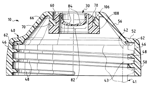
FIG. 1 is an enlarged, cross-sectional view of a
dispensing system of the present invention in the form of a
valve for use as part of a dispensing closure shown
threadingly mounted to the neck of a container (shown in
phantom with dashed lines);
FIG. 2 is a side elevational view of the valve
employed in the dispensing closure shown in FIG.1;
FIG. 3 is a top plan view of the valve shown in
FIG. 2;
CA 02387778 2008-05-02
23158-1804
-9b-
FIG. 4 is a side elevational view of the valve
shown in FIG. 2;
CA 02387778 2002-04-17
WO 01/32552 PCT/USOO/40927
-10-
FIG. 5 is an enlarged, fragmentary, cross-sectional view of the valve
in the dispensing system on the container shown in FIG. 1 with the assembly
in an inverted orientation prior to dispensing product from the container;
FIG. 6 is a view similar to FIG. 5, but FIG. 6 shows a pressure
increase in the container (as when the container is being squeezed) acting on
the valve just prior to the valve opening to discharge product from the
container; and
FIG. 7 is a view similar to FIG. 6, but FIG. 7 shows a further
orientation of the valve as the container interior is subjected to even
greater
pressure which causes the valve to move to its fully open condition for
dispensing product from the container.
DESCRIPTION OF THE PREFERRED EMBODIMENTS
While this invention is susceptible of embodiment in many different
forms, this specification and the accompanying drawings disclose only one
specific form as an example of the invention. The invention is not intended
to be limited to the embodiments so described, and the scope of the
invention will be pointed out in the appended claims.
For ease of description, the dispensing components are described
herein in various positions, and terms such as upper, lower, horizontal, etc.,
are used with reference to these positions. It will be understood, however,
that the components may be manufactured, stored, and used in orientations
other than the ones described.
A presently preferred embodiment of a dispensing system of the
present invention is illustrated in FIG. 1. The dispensing system is provided
in the form of a single, unitary valve 30 adapted to be mounted in the
discharge opening of a dispensing end structure, such as the discharge end of
a container, or as illustrated, in a closure body 40 so as to form a closure
10
which is adapted to be mounted on a container 41 (FIG. 5).
WO 01/32552 CA 02387778 2002-04-17 pCT/US00/40927
-11-
The container 41 has a conventional mouth or opening 42 defined by
a neck 43 or other suitable structure. The neck 43 typically has (but need
not have) a circular cross-sectional configuration, and the body of the
container may have another cross-sectional configuration, such as an oval
cross-sectional shape, for example.
The container 41 may typically be a squeezable container having a
flexible wall or walls which can be grasped by the user and compressed to
increase the internal pressure within the container so as to squeeze the
product out of the container through the closure when opened. The container
wall typically has sufficient, inherent resiliency so that when the squeezing
forces are removed, the container wall returns to its normal, unstressed
shape. Such a structure is preferred in many applications, but may not be
necessary or preferred in other applications.
The closure body 40 could optionally include a lid (not illustrated)
which may be hingedly attached or may be a completely separate, removable
component.
The closure body 40 includes an annular skirt or wall 46 which may
have suitable connecting means (e.g., a conventional thread 48 (FIG. 1) or a
conventional snap-fit bead (not illustrated)) for engaging a suitable
container
cooperating means, such as a thread 50 on the container neck 43 (or bead,
not shown) to secure the closure body 40 to the container 41. The closure
body 40 and container 41 could also be fixed together by induction melting,
ultrasonic melting, gluing, or the like.
The closure body 40 could alternatively be molded as a unitary part
of the container neck 41 to define a dispensing end structure directly on the
container 41. In such a design, the container and closure body would be
molded as a single, unitary, dispensing end structure, and that would
eliminate the need for threaded connection features, or other connection
features, on the container. The unitary container/closure body structure
would have to be initially molded with an "open" bottom to accommodate
WO 01/32552 CA 02387778 2002-04-17 PCTIUSOO/40927
-12-
subsequent insertion of the valve 30 through the container open bottom and
into engagement with the unitary closure body at the dispensing end of the
container. The container could then be inverted and filled through the open
bottom, after which the open bottom could be closed with a suitable
operation (e.g., installing a bottom closure component or deforming the
container bottom into a permanently closed configuration).
Near the top of the annular wall 46, the closure body 40 has a deck
comprising a first, most outwardly, annular shoulder 52. A spout 56 projects
from the shoulder 52. The spout 56 terminates in an outer discharge
opening 60 over the container neck opening 42.
Preferably, an annular, flexible "crab's claw" shape seal 62 projects
from the bottom of the deck shoulder 52 and is received against the upper
edge of the container neck 43 adjacent the container neck opening 42 so as
to provide a leak-tight seal between the closure body 40 and the container
neck 43. Of course, other types of closure base/container seals may be
employed. Also, if air-tightness is not required, no closure base/container
seal 62 need be employed.
The container 41 and closure body 40 may be normally stored in the
upright orientation wherein the closure body 40 is at the top of the container
41. The container 41 and closure body 40 may also be stored in an inverted
position. When the package is stored in the inverted position, the closure
body 40 functions as a support base, and the valve 30 holds the product
within the container 41 unless the container 41 is squeezed.
The closure body 40 includes an annular wall 66 defining the
discharge opening 60. At the bottom of the annular wall 66 there is an
annular mounting flange 70 which extends radially inwardly from the wall
66.
The preferred form of the valve 30 is illustrated FIGS. 2-4. The
valve 30 employs "head" and "connecting sleeve" portions of a known design
employing a flexible, resilient material which can open to dispense product
CA 02387778 2008-05-02
23158-1804
-13-
as described in detail hereinafter. The valve 30 may be molded from
thermosetting elastomeric materials, such as natural rubber and the like. The
valve 30 is preferably from silicone rubber sold by Dow Chemical Company
in the United States of America under the trade designation DC-595.
However, the valve 30 can also be molded from thermoplastic elastomers
based upon materials such as thermoplastic propylene, ethylene, urethane, and
styrene, including their halogenated counterparts.
The valve 30, when molded from these materials, is flexible, pliable,
elastic, and resilient so that a marginal portion thereof can be temporarily
and elastically deformed as it is mounted to, and sealingly engaged with, the
spout mounting flange 70.
As shown in FIG. 4, the valve 30 includes a centrally disposed active
portion 80. The valve active portion 80, in the preferred embodiment
illustrated, has the configuration and operating characteristics of a
commercially available valve design substantially as disclosed in the U.S.
Patent No. 5,409,144 with reference to the valve 3d disclosed in the U.S.
Patent No. 5,409,144. The operation of such a commercially available valve
is described with reference to the valve that is designated by reference
number 3d in the U.S. Patent No. 5,409,144.
As illustrated in FIG. 4 herein, the valve active portion 80 includes a
flexible, central, head portion or central wall 82 which has an outwardly
concave configuration and which defines at least two, intersecting, dispensing
slits 84 extending through the head portion or central wall 82 to define a
dispensing orifice. A preferred form of the valve 30 has two, mutually
perpendicular, intersecting slits 84 of equal length. The intersecting slits
84
define four, generally sector-shaped, flaps or petals 85 (FIG. 7) in the
concave, central wall 82. The flaps 85 open outwardly from the intersection
point of the slits 84 in response to increasing pressure of sufficient
CA 02387778 2002-04-17
WO 01/32552 PCTIUSOO/40927
-14-
magnitude in the well-known manner described in the above-discussed U.S.
Patent No. 5,409,144.
The active portion 80 of the valve 30 includes a connector sleeve or
skirt 86 (FIG. 4) which extends outwardly from the valve head portion or
central wall 82. The outer (upper) end of the connector sleeve 86 includes a
thin, annular flange 88 (FIG. 4) which extends peripherally from the skirt 86
to define an upwardly curved portion 90 and a downwardly angled portion
92. The thin flange 88 terminates in an enlarged, much thicker, peripheral
marginal portion 100.
The marginal portion 100 is connected with the valve head portion 82
through the connector sleeve 86 and has a generally annular wall 102
defining a generally annular groove 104 (FIG. 4) which is open radially
outwardly for receiving the closure mounting flange 70. The annular wall
102 is sufficiently flexible to temporarily deform as the wall 102 is forced
against the mounting flange 70 to accommodate seating of the mounting
flange 70 in the groove 104. The annular wall 102 is also sufficiently
resilient to accommodate the retention of the mounting flange 70 in the
groove 104 by adjacent portions of the wall 102.
The generally annular wall 102 includes a generally annular, upper
shoulder 106 and a generally annular, lower, retention flange 108. The
groove 104 is located below the shoulder 106 and above the retention flange
108.
The upper shoulder 106 defines a generally frustoconical lead-in
surface 110 (FIG. 4) facing generally away from the retention flange 108.
The upper shoulder 106 also defines a generally annular undercut surface
112 which faces generally toward the retention flange 108 and which defines
one side of the groove 104. The retention flange 108 has a generally
flat, annular, upper surface 114 defining one side of the groove 104 and
facing toward the undercut surface 112. In the preferred embodiment
CA 02387778 2002-04-17
WO 01/32552 PCT/US00/40927
- 15-
illustrated in FIG. 4, the retention flange 108 extends radially outwardly
beyond the radial extent of the upper shoulder 106.
The valve 30 can be readily assembled with the closure body 40 by
forcing the valve 30 into the closure body 40 from the underside or interior
side of the closure spout 56. The valve frustoconical lead-in surface 110
engages the bottom, inner peripheral edge of the mounting flange 70. The
frustoconical lead-in surface 110 tends to provide a self-centering action for
the valve 30 as it is forced upwardly against the flange 70. The valve 30
deforms, by being compressed generally radially inwardly, sufficiently to
permit the upper shoulder 106 to move past the mounting flange 70 so that
the valve 30 snaps into a tight engagement wherein the mounting flange 70
is received in the groove 104 of the valve 30. Preferably, the height of the
groove 104 is very slightly less than the thickness of the mounting flange 70
so as to provide a tight sealing engagement between the valve 30 and the
mounting flange 70.
In the preferred embodiment, the groove 104 is defined at a location
along the annular wall 102 to locate the sleeve 86 and head portion 82
within the discharge opening 60. That is, the sleeve 86 and head portion 82
are located inwardly of the outer end of the discharge opening 60 so that the
valve 30 does not project outwardly beyond the discharge opening 60 when
the valve head portion is closed while the valve 30 is mounted to the flange
70 and sealingly disposed with respect to the discharge opening 60.
Preferably, the lower retention flange 108 has a height (e.g., along the
vertical axis of the valve 30) which exceeds the height of the groove 104.
This provides a relatively substantial anchor function or retention function
and better resists forces that might tend to separate the valve 30 from the
annular flange 70.
The above-described mounting structure of the dispensing system of
the present invention can be readily assembled in a manner which does not
require a separate snap-fit clamping member or a separate retainer collar for
CA 02387778 2002-04-17
WO 01/32552 PCT/US00/40927
-16-
threaded attachment which could impose undesirable stresses or torque on the
valve 30, which stresses and torque could affect the operation of the valve.
The structure of the dispensing system of the present invention
simplifies the equipment required for assembly, and the process of
assembling the system is less costly. The dispensing system can incorporate
a valve 30 of various diameters, slit sizes, and head configurations.
When the valve 30 is properly mounted within the closure body 40 as
illustrated in FIGS. 1 and 5, the head portion 82 of the valve 30 lies
recessed within the closure body dispensing opening 60. However, when the
container 41 is squeezed to dispense the contents through the valve 30 (as
described in detail in the U.S. Patent No. 5,409,144), then the valve head
portion 82 is forced outwardly from its recessed position toward the upper
end of the dispensing passage or opening 60 (FIG. 6).
In use, the container 41 is typically inverted and squeezed to increase
the pressure within the container above the ambient pressure. This forces the
product within the container toward the valve 30 and forces the valve 30
from the recessed or retracted position (illustrated in FIGS. 1 and 5) toward
the outwardly extending position. The outward displacement of the valve
head portion 82 is accommodated by the relatively thin connector sleeve 86.
The sleeve 86 moves from an inwardly projecting, rest position to the
pressurized position wherein the sleeve 86 rolls outwardly toward the outside
of the closure body 40. However, the valve 30 does not open (i.e., the slits
84 do not open) until the valve head portion 82 has moved substantially all
the way to a fully extended position adjacent or beyond the dispensing
passage 60. Indeed, as the valve head portion 82 moves outwardly, the
valve head portion 82 is subjected to radially inwardly directed compression
forces which tend to further resist opening of the slits 84. Further, the
valve
head portion 82 generally retains its outwardly concave configuration as it
moves outwardly and even after it reaches the fully extended position.
However, when the internal pressure becomes sufficiently high (so that the
CA 02387778 2002-04-17
WO 01/32552 PCT/USOO/40927
-17-
difference between the interior pressure and exterior pressure exceeds a
predetermined amount), then the slits 84 of the valve 30 begin to open to
dispense product (FIG. 7). The product is then expelled or discharged
through the open slits 84. For illustrative purposes, FIG. 6 shows a drop of
liquid product 130 being discharged.
It will be readily observed from the foregoing detailed description of
the invention and from the illustrations thereof that numerous other
variations
and modifications may be effected without departing from the true spirit and
scope of the novel concepts or principles of this invention.