Note: Descriptions are shown in the official language in which they were submitted.
CA 02388486 2002-08-21
MATERIAL DRYING ARRANGEMENT
BACKGROUND OF THE INVENTION
The present invention relates to a material drying arrangement and more
particularly
to a unified apparatus and method for drying materials such as fabric in a
selected location
with a drying stream modulated in flow and temperature by a blower and heating
member,
respectively, which are controlled in accordance with coordinated sensed
upstream and
downstream temperatures and relative humidity.
It is known in the prior art to utilize dryer apparatus responsive to either
or both sensed
temperatures and relative humidities. In this regard, attention is directed to
U.S. Patents No.
4,086,707, issued to S. Bochan on May 2, 1978, No. 4,231,166, issued to S.L.
McMillan on
November 4, 1980; No. 4,267,643, issued to J.C. Hariedon on May 19, 1981 and
No.
4,891,893, issued to R.K. Narang on January 9, 1990. These four patents teach
various
arrangements for clothes dryers responsive to sensed temperatures in heated
drying air.
Attention is further direct to U.S. Patents No. 6,079,121, issued to P.S.
Khadkikar, et al, on
June 27, 2000 and No. 6,122,840, issued to N. W. Chbat et al on Sept. 26,
2000, both of which
teach arrangements wherein clothes dryers are responsive to humidity changes.
In addition,
attention is directed to the three U.S. Patents No. 5,315,765, issued to M.
Holst et al on May
31, 1994, No. 6,098,310, issued to Y-T Chen et al on August 8, 2000 and to No.
6,141,887
issued to Y-T Chen et al on November 7, 2000, all three of which patents teach
clothes dryer
arrangement wherein clothes dryers are responsive to both sensed temperatures
and humidities
- it being noted that Patent No. 5,315,765, senses temperature and humidity at
both clothes
dryer intake and exhaust. Finally, attention is directed - as of general
interest - to the clothes
dryer arrangements of U.S. Patents No. 4,546,554, issued to N.J. Bullock et al
on October 15,
1985 and No. 6,115,680, issued to W.D. Barritt on September 19, 2000, it being
noted that
the maj ority of the above referenced patents are directed to clothes dryer
structure adapted in
residential usage wherein clothes drying loads are substantially less than the
larger loads
familiar in commercial drying situations.
The present invention provides a unique material drying arrangement which can
be
utilized for both commercial and residential drying, which provides a novel
healing and
ventilating arrangement requiring a minimum of novel parts to construct and
maintain and
1
CA 02388486 2003-02-25
which provides a minimum of novel steps to operate. 'The present invention
further provides
for comparatively more efficient, economical, and straight forward operational
control with
a comparatively larger energy savings, efficiently utilizing less energy with
the efficient
consumption of lower amounts of gas and electrical energy.
It is to be understood that various other features of the present invention
will become
obvious to one skilled in the art upon reading the disclosure set forth
herein.
BRIEF SUMMARY OF THE INVENTION
More particularly the present invention provides a unique and novel material
dryer
apparatus including a housing with a drying basket disposed therein and having
a drying
stream heater and blower associated therewith, a control arrangement for the
dryer apparatus
comprising: temperature sensing means disposed to sense the drying stream
temperatures
entering upstream and exiting downstream the drying basket; relative humidity
sensing means
disposed to sense the drying stream relative humidity entering upstream and
exiting
downstream the drying basket; and control means connected to the temperature
sensing means
and the relative humidity sensing means, the control means being connected to
the heater and
the blower to cooperatively and intermittently modulate drying heat input and
drying stream
volume delivery in the heater and the blower with respect to each other and in
accordance
with sensed temperatures and relative humidity levels entering upstream and
exiting
downstream the said dryer basket.
Further, the present invention provides a unique and novel method of drying
material
to a selected moisture level comprising: introducing the material in a drying
zone; measuring
the temperature and relative humidity of a material drying stream passing
through the drying
zone along both at the upstream inlet and downstream outlet of the drying
zone; and
cooperatively and intermittently controlling the heating and flow of the
drying stream passed
through the drying zone with respect to measured upstream and downstream
temperature and
relative humidity whereby material removed from said drying zone has a select
moisture level
for further treatment with selected drying of the material being accomplished
at an optimal
energy level.
It is to be understood that one or more changes can be made by one skilled in
the art
in one or more of the several parts of the apparatus disclosed herein and in
one or more of the
2
CA 02388486 2002-08-21
several steps of the method disclosed herein without departing from the scope
or spirit of the
present invention. Further, it is to be understood the unique and novel
unified apparatus and
method as disclosed is not to be considered as limited to fabric treatment
such as clothing or
garments but can be utilized in other heating and ventilating environments
where temperature
and relative humidity control are involved. Moreover, although the unified
arrangement
herein disclosed has significant energy saving capabilities in commercial
environments it
would also have such similar capabilities in residential environments.
BRIEF DESCRIPTION OF THE DRAWINGS
Referring to the drawings which disclose a schematic arrangement of one
embodiment
of the present invention:
Figure 1 is an isometric, broken away partial view of a portion of the novel
drying
apparatus of the present invention, disclosing portions of the front, rear and
one side of the
novel drying apparatus;
Figure 2 is a front end vertical view of the novel drying apparatus of Figure
l;
Figure 3 is a schematic broken away vertical side view of the novel drying
apparatus
of Figure 1;
Figure 4 is a rear end vertical view of the novel drying apparatus of Figure
1;
Figure 5 is a schematic, broken away, vertical front sectional view of the
line of stream
drying flow view of the novel drying apparatus of Figures 1-4, and;
Figure 6 is a schematic, electrical circuit for the novel drying apparatus of
Figures 1-5.
DETAILED DESCRIPTION OF THE INVENTION
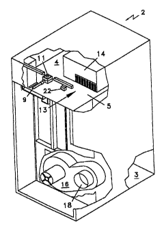
Referring to the unique and novel commercial dryer arrangement as disclosed in
the
broken away, isometric view of Figure 1, a rectangularly shaped dryer housing
2, which can
be formed from any one of several strong, substantially rigid materials, such
as a suitably
coated sheet metal, can be seen. Housing 2 serves to define a large drying
chamber 3 and an
upper chamber 4 partitioned by horizontal partition 5. As can be seen in the
broken away
schematic view of Figure 5, drying chamber 3 serves to include amotor driven,
reciprocating
rotatable perforated drying basket 6 which holds and rotates the materials to
be heat dried.
The materials to be heat dried are passed to dryer basket 6 through the hinged
door 7 at the
CA 02388486 2002-08-21
front end of housing 2, the door 7 being provided with a transparent glass or
plastic material
viewing sealed porthole 8 (Figure 2).
Again, referring to Figure 1 of the drawings, the partitioned, upper chamber
4,
incorporates a gas feed pipe 9 feeding burners 10 (Figure 5). Pipe 9 is
connected to a suitable
external gas supply source (not shown). Gas feed pipe 9 incorporates a gas
valve 1 l, which
is controlled in an intermittent manner described hereinafter through a
humidity and
temperature control sensors 21 and 22 and which also is disposed in chambers 3
and 4.
Chamber 4 is provided with a rear chamber inlet 13 (Figure 1) through which a
suitable
drying fluid to be heated, such as ambient air, can be introduced into chamber
4. Chamber
4 includes a secondary chamber 14, which serves as a heating unit with ambient
air passing
from chamber 4 into secondary unit 14 (Figure 5). It is to be understood that
fabric material
can be inserted through hinged door 7 with porthole 8 (Figure 3) into the
motor driven,
perforated, rotatable drying basket 6 (Figure 5).
Disposed in the lower portion of chamber 3, defined by housing 2 is a
rotatable motor
driven centrifugal blower 16 (Figures 1, 3, 4 and 5) which serves to draw a
heated drying
stream from gas heating drying chamber 14 into chamber 3 through motor driven
rotatable
perforated drying basket 6 over the fabric materials inserted into the drying
basket 6 and
ultimately through the blower inlet 17 of blower 16 (Figure 5) and through
exhaust outlet 18,
in housing 2 (Figures l and 5) the exhaust outlet of fan or blower 16 being
connected thereto.
As can be seen in Figures 3 and 4 of the drawings, a temperature and humidity
sensor
21 is provided in the lower drying chamber 3, serving to sense the exhaust
temperatures and
relative humidity in compatible intermittent cooperation with temperature and
humidity
sensor 22 in upper chamber 4 above partition 5, all in accordance with the
present invention
and the inventive circuitry described hereinafter. In this regard, it is to be
noted that a suitable
programmable humidity and temperature circuitry controller 23 is mounted on
the upper front
face of housing 2 (Figure 2) and that a reversing motor inverter 24 (Figure 3)
is suitably
mounted below partition 5 in the upper rear of housing or cabinet 2 (Figures 3
and 4), these
two units 23 and 24 being an important part of the inventive circuitry 26 of
Figure 6 as
described hereinafter.
In accordance with the present invention, it is to be noted that the blower
motor speed
for blower 16 can operate in the low frequency range of approximately thirty
(30) Hertz (Hz)
4
CA 02388486 2002-08-21
to a high frequency range of approximately sixty Hertz. The heater can operate
in such
embodiment in the high heating range of approximately one hundred eighty
thousand
( 180,000) British Thermal Units (BTU) to the Low heating range of
approximately seventy-
eight-thousand (78,000) British Thermal Units (BTU). In this regard, it is to
be further noted
that control 23 can be provided with multiple relative humidity settings and
temperature
control settings which can range up to ten ( 10) relative humidity settings
and for temperature
settings in the Fahrenheit range of approximately thirty two (32) to one
hundred ninety seven
( 197) degrees Fahrenheit (F°). It is to be understood that the High
and Low intermittent
frequency ranges and BTU ranges can be varied by one skilled in the art
according with
material and dryer demands.
Referring to the inventive circuitry 26 of the present invention, a three (3)
phase (PH)
line L1, L2, L3 is disclosed capable of carrying two hundred (200) to six
hundred (600) volts
(v) is disclosed for use with commercial dryers. It is to be understood that
the present
inventive circuitry could be employed with lower voltage single or three-phase
circuitry
delivery. Lines L1, L2, L3 can be seen as directly connected to fan or blower
motor 27 for
the centrifugal fan or blower 16 through normally open variable speed drive
contacts 28, 29,
and 31 respectively.
Also, connected across lines L 1, L2 and L3 is the basket motor 32 for
rotation of the
above-mentioned drying basket 6. As can be seen, basket motor 32 is connected
in parallel
to fan motor 27 and to the three phase lines L1, L2 and L3, through line set
34, 35 and 36 and
line set 37, 38 and 39 respectively, with suitable sets of normally open
forward drive contacts
41, 42 and 43 and normally open reverse contacts 44, 46, and 47 being employed
in the two
sets of line set 34, 35 and 36 and line set 44, 46 and 47, respectively.
Connected across lines L 1, L2 of the three phase line L 1, L2 and L3 through
a twenty-
four (24) volt (v) step-down transformer 48 are step down lines SL1 and SL2.
Four lines, 49,
51, 52 and 53 extend between SL1 and SL2 and two additional lines 54 and 56
extend
between line 53 and SL2. Connected in line 49 is the above-discussed
controller 23
(PROHC). As above noted, this controller 23, which is fastened to the front
face of housing
2 (Figure 2) serves to modulate the heat and blower 16 through temperature and
humidity
sensor 21, located in chamber 3 of housing 2 and the temperature and humidity
sensor 22,
located in upper chamber 4 of housing 2. Extending along line 51 between lines
SL l and SL2
CA 02388486 2002-08-21
and within control 23 is a cycle switch 57. Line 51 further includes an energy
smart relay 58
positioned in line 51 outside dryer control 23. Line 52 extending between
lines SL 1 and SL2
includes an air switch 59, outside control 23, a heat switch 61 within control
23, and again
outside control 23 but in line 52 are basket and bonnet thermostats 62 and 63
respectively.
The basket thermostat can be appropriately positioned in chamber 3 of housing
2 proximate
drying basket 6 and the bonnet thermostat can be appropriately positioned in
chamber 4 of
housing 2 above partition 5. Also positioned in line 52 outside control 53 is
a direct spark
igniter 64. Connected to igniter 64 is a line 66, the opposite end of which
line 66 is connected
to line SL2. A further line 67 extends between line 66 and line SL2. Line 66
includes an
energy smart relay contact 68 and High BTU gas valve 69. Line 67 includes
parallel lines 67'
and 67" connecting in parallel with Low BTU main gas valve 71 and a redundant
gas valve
72.
Positioned in line 53 extending between lines SL1 and SL2 outside dryer
control 23
is a lint door switch 73 and a door reed switch 74. A switch 76 within dryer
control 23 serves,
when closed, to energize in line 53 forward contactor 77. In lines 54
extending between line
53 and line SL2, a switch 78, also within dryer control 23, serves, when
closed, to energize
reverse contactor 79 in line 54 - both contactors 77 and 79 being outside
dryer control 23.
In line 56 which also extends between line 53 and line SL2, a fan or blower
switch 81 for
blower 16 is included in control 23 and outside control 23 in line 56 is a
variable speed drive
or frequency controller 82. This variable speed drive 82 or frequency
controller includes line
84 having an energy smart relay contact 83 connected in line 84 calling for
High blower
speed.
Finally, connected in the lower portion of dryer control 23 is a rotation
sensor 86, a
line 87 including a door reed switch 88 and a lint door switch 89. Dryer
control 23 also
includes humidity and temperature sensors 21 and 22.
From the description of this electrical control circuit 26, it can be seen
that the
inventive dryer arrangement is capable of a unique control wherein the heat
and the blower
16 are efficiently controlled through cooperative intermittent modulation of
sensed inlet
temperatures and relative humidities which are modulated intermittently with
sensed outlet
temperatures and relative humidities - all in an efficient, straight forward
manner with a
6
CA 02388486 2002-08-21
minimum of parts and a minimum of operating steps and with a minimum of energy
usage
and cost.
In a typical operation of the inventive arrangement, the temperature and
humidity
sensors 21 and 22 located in chambers 3 and 4 respectively communicate the
measurements
of a dryer control 23 which averages these measurements to obtain an operative
relative
humidity and temperature. The controller 23 is provided with a select number
of relative
humidity settings - approximately ten (10) - and a definite number of settings
for
temperatures -betweenthiriy-two (32) to onehundredninety seven (197) degrees
Fahrenheit
(F°). At a preset relative humidity (switch point) controller 23 will
switch a contact connected
to variable speed drive 82, which is connected to fan motor 27, allowing the
fan motor 27 to
run on preset levels of frequency ranging from sixty (60) down to thirty (30)
Hertz (Hz). At
the same time, contacts also switch a two-stage High-Low gas valve arrangement
in lines 66
and 67 - thus resulting in an approximately twenty (20) percent (%) gas usage
savings. With
the relative humidity switch point set at a High level, the inventive dryer
starts with a High
BTU input and a Low cubic feet per minute blower 16 input. When the sensors
read a preset
average relative humidity, controller 23 switches the two-stage High-Low gas
valve
arrangement so as to obtain a Low Heat input and switches the frequency drive
controller to
obtain a High cubic feet per minute (cfm) flow.
7