Language selection

Search

Patent 2388513 Summary

Third-party information liability

Some of the information on this Web page has been provided by external sources. The Government of Canada is not responsible for the accuracy, reliability or currency of the information supplied by external sources. Users wishing to rely upon this information should consult directly with the source of the information. Content provided by external sources is not subject to official languages, privacy and accessibility requirements.

Claims and Abstract availability

Any discrepancies in the text and image of the Claims and Abstract are due to differing posting times. Text of the Claims and Abstract are posted:

  • At the time the application is open to public inspection;
  • At the time of issue of the patent (grant).
(12) Patent: (11) CA 2388513
(54) English Title: POWER STATION USING OCEAN CURRENTS
(54) French Title: CENTRALE ELECTRIQUE UTILISANT LES COURANTS MARINS
Status: Expired
Bibliographic Data
(51) International Patent Classification (IPC):
  • F03B 17/06 (2006.01)
  • F03B 3/12 (2006.01)
  • F03B 13/10 (2006.01)
(72) Inventors :
  • WOBBEN, ALOYS (Germany)
(73) Owners :
  • WOBBEN, ALOYS (Germany)
(71) Applicants :
  • WOBBEN, ALOYS (Germany)
(74) Agent: OYEN WIGGS GREEN & MUTALA LLP
(74) Associate agent:
(45) Issued: 2005-01-04
(86) PCT Filing Date: 2000-08-08
(87) Open to Public Inspection: 2001-04-12
Examination requested: 2002-10-04
Availability of licence: N/A
(25) Language of filing: English

Patent Cooperation Treaty (PCT): Yes
(86) PCT Filing Number: PCT/EP2000/007665
(87) International Publication Number: WO2001/025627
(85) National Entry: 2002-04-03

(30) Application Priority Data:
Application No. Country/Territory Date
199 48 198.9 Germany 1999-10-06

Abstracts

English Abstract


The invention concerns a marine current power installation. This
involves not just a known tidal power installation which makes use of the
energy of tidal ebb and flow, but a power installation which takes energy
from marine currents which constantly occur over all oceans.
The invention proposes designing a marine current power
installation which takes kinetic energy of flow from the marine current and
converts the taken energy into electrical energy. In that case the marine
current water power installation according to the invention is used below
the water level, for example more than 50 m below the water level, and
can make a relatively large amount of power available even when the flow
speed of the marine current is relatively low, for example in the region of
1.5 m/sec or less. That is achieved in that the water power installation
has a water wheel or a rotor (turbine or propeller) which is of a diameter
of for example 10 m or more, preferably between 30 m and 120 m.


French Abstract

L'invention concerne une centrale électrique utilisant les courants marins. Cette centrale est transportable. Son boîtier et son rotor creux peuvent être remplis d'eau à volonté ou vidés. Cela permet de régler ou de modifier la profondeur d'immersion de la centrale.

Claims

Note: Claims are shown in the official language in which they were submitted.


CLAIMS
1. A transportable marine current power installation comprising a housing
which accommodates a generator comprising a generator rotor and a genera-
tor stator, wherein the generator is driven by means of a rotor which is
connected to the generator rotor and wherein the power installation is ar-
ranged in an extensive marine current installation which is an oceanic current
system, wherein a rotor of the power installation has at least one rotor blade
which carries the generator rotor of the generator of the power installation
and
wherein the at least one rotor blade of the power installation has at least
one
cavity which can be flooded with water, and wherein the generator stator is
arranged in said housing such that by the interaction between the generator
rotor and the generator stator said generator produces electrical energy.
2. A marine current power installation according to claim 1, characterised
in that the least one cavity of the rotor blades are configured to be flooded
with water to be possibly displaced again.
3. A marine current power installation according to claims 1 or 2, charac-
terised in that the housing of the power installation is formed at least in
part
as a concentrator, by means of which the flow speed of the water passing into
the power installation is increased.
4. A marine current power installation according to one of the claims 1 to
3, characterised in that the housing of the power installation has closed
cavities which can be flooded with water and from which the water can
possibly be displaced again.

Description

Note: Descriptions are shown in the official language in which they were submitted.


CA 02388513 2004-O1-02
POWER STATION USING OCEAN CURRENTS
The invention concerns a marine current power installation. This
involves not just a known tidal power installation which makes use of the
energy of tidal ebb and flow, but a power installation which takes energy
from marine currents which constantly occur over all oceans.
Such marine currents are usually large-area stationary current
systems, the production of which can be decisively attributed to the thrust
force of the wind at the surface of the sea (drift current), internal pressure
forces (gradient current) and the rotation of the Earth (Coriolis force) and
the topography of the ocean bottom and the coasts. As the most
important marine currents mention may be made by way of example of
the North and South Equatorial Currents, the Kuroshio, the East Australian
Current, the Gulf Stream, the Brazil Current, the Agulhas Current, the
North Pacific Current, the North Atlantic Current, the West Wind Drift, the
Californian Current, the Humboldt Current, the Canary Current, the
Benguela Current, the Western Australian Current, Equatorial
Countercurrents, the Alaska Current, the Norwegian Current, the West
Spitsbergen Current, the East Greenland Current, the Labrador Current,


CA 02388513 2004-07-21
2
the Irminger Current, the Oyashio and the Falklands current. Besides the known
surface currents in the oceans there are pronouncedly in the Atlantic and
Pacific
Oceans the Equatorial Sub-currents (up to 2.5 m/sec flow speed) which at a
depth of
around 100 m (or deeper) flow eastwards directly onto the Equator under the
westwardly directed South Equatorial Current.
The invention proposes designing a marine current power installation which
takes kinetic energy of flow from the marine current and converts the taken
energy into
electrical energy. In that case the marine current water power installation
according to
the invention is used below the water level, for example more than 50 m below
the
water level, and can make a relatively large amount of power available even
when the
flow speed of the marine current is relatively low, for example in the region
of 1.5 m/sec
or less. That is achieved in that the water power installation has a water
wheel or a
rotor (turbine or propeller) which is of a diameter of for example 10 m or
more,
preferably between 30 m and 120 m.
Brief Description of Drawings
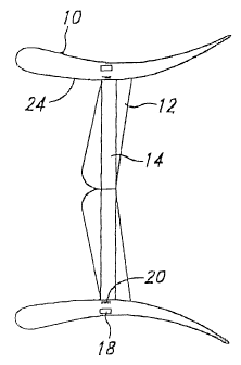
Figure 1 shows a cross-sectional view of a marine current power generation
structure.
Figure 2 is a cross-sectional view of the marine current power generation
structure according to the present invention having chambers therein.
Detailed Description of the Invention
Figure 1 shows by way of example a view in cross-section of a marine current
water power installation according to the invention. This power installation
has an
annular housing 10 which has a very high level of strength. The annular
housing is
also in the form of a concentrator (duct casing) 24, 23 so that the flow speed
of the
water passing into the ring is increased. Provided in the central region of
the
housing is a water wheel or propeller 14 which is driven by the flow speed of
the
water. It rotates and in so doing at the same time drives a generator rotor 20
of a
generator. In this embodiment, the generator is not coupled with a shaft to
the
turbine but the pole


CA 02388513 2004-07-21
3
wheel of the generator rotor 20 is fixed externally to the water wheel.
Accordingly,
the water wheel or the rotor 20 of the power installation carries the
generator rotor
20 at its tip which is surrounded by a generator stator 18 in the housing 24,
23 of the
water power installation. The forces acting on the water wheel are carried by
main
bearings which rest on a support spider 12 which passes through the housing
ring.
As shown in Figure 2, preferably the rotor 20 or the water wheel and/or the
housing of the water power installation has chambers 22, which may also be
called
cavities 22, which can be flooded so that a condition of equilibrium of the
water
power installation in relation to the water occurs. That ensures that the
bearing
arrangement of the water power installation only has to still carry the thrust
of the
flowing water.
As shown in Figure 2, the cavities 22 can be filled with air when transporting
the water power installation to the position of installation. A ship can thus
easily
transport the water power installation in a floating condition to the position
of
installation. As soon as the water power installation has reached its intended
position of installation the cavities 22, according to the desired depth and
design for
that location, are filled to a selected level with water, preferably sea
water, so that
the water power installation can slowly sink to the desired depth, whether to
the
partially submerged, fully submerged, or to selected depth or completely to
the
bottom. If conversion of the water power installation or repair should be
necessary,
the water can be removed out of the cavities 22 and it will easily float
again.
It is possible for the water power installation to be both directly anchored
to
the bed and/or to be fixed at a certain spacing from the ocean floor by
suitable
cables or chains which are arrested on the ocean floor, or other structures.
The energy which is produced by the generator is carried away by means of
cables and fed directly into the energy network. It is also possible for the
energy
produced by the marine current water power installation to be used to supply
power
to sea water desalination plants.
Even if marine currents involve relatively low flow speeds, the following
numerical example can make it clear that very large amounts of electrical
energy
(and a corresponding power of more than 500 KW) can be produced, depending on
how high the respective marine current speed is and how large the diameter of
the


CA 02388513 2004-O1-02
4
water wheel of the power installation is.
Thus, it is for example possible to already produce a power output of 500 KW
with a marine current speed of 1.5 m/sec and a water wheel diameter of 25 m.
If the
diameter of the water wheel is increased to 80 m a power output of 5 MW is
possi-
ble. With a water wheel diameter of 36 m a power output of 1 MW is still
possible.
If the marine current speed rises then the amount of electric power rises with
the third power in relation thereto.
The particular advantage of the marine current power installation according to
the invention is that it can be used where in practice the power installation
itself does
not adversely affect the environment. At the same time the marine current
power
installation can make available an energy source which is almost inexhaustible
and
the behavior of which is very accurately predictable. In spite of the size of
the
marine current water power installation, by virtue of flooding of the cavities
22 or by
virtue of expelling the water from the cavities 22, the power installation can
be very
accurately positioned in the marine currents where it does not have any
adverse
influence on shipping because it is below the usual draughts of sea-going
vessels.
It should be noted that the marine current power installation according to the
invention can also be employed to make use of ebb and flow currents which
regularly occur with a tide. For that purpose it is desirable for the rotor 20
blades to
be so designed that they can convert flows from both sides (rotation in two
different
directions) or can preferably turn with a change in the flow direction.

Representative Drawing
A single figure which represents the drawing illustrating the invention.
Administrative Status

For a clearer understanding of the status of the application/patent presented on this page, the site Disclaimer , as well as the definitions for Patent , Administrative Status , Maintenance Fee  and Payment History  should be consulted.

Administrative Status

Title Date
Forecasted Issue Date 2005-01-04
(86) PCT Filing Date 2000-08-08
(87) PCT Publication Date 2001-04-12
(85) National Entry 2002-04-03
Examination Requested 2002-10-04
(45) Issued 2005-01-04
Expired 2020-08-10

Abandonment History

There is no abandonment history.

Payment History

Fee Type Anniversary Year Due Date Amount Paid Paid Date
Application Fee $300.00 2002-04-03
Maintenance Fee - Application - New Act 2 2002-08-08 $100.00 2002-04-03
Request for Examination $400.00 2002-10-04
Advance an application for a patent out of its routine order $100.00 2002-10-11
Maintenance Fee - Application - New Act 3 2003-08-08 $100.00 2003-06-20
Maintenance Fee - Application - New Act 4 2004-08-09 $100.00 2004-06-16
Final Fee $300.00 2004-10-20
Maintenance Fee - Patent - New Act 5 2005-08-08 $200.00 2005-07-21
Maintenance Fee - Patent - New Act 6 2006-08-08 $200.00 2006-07-20
Maintenance Fee - Patent - New Act 7 2007-08-08 $200.00 2007-07-19
Maintenance Fee - Patent - New Act 8 2008-08-08 $200.00 2008-07-28
Maintenance Fee - Patent - New Act 9 2009-08-10 $200.00 2009-07-28
Maintenance Fee - Patent - New Act 10 2010-08-09 $250.00 2010-07-27
Maintenance Fee - Patent - New Act 11 2011-08-08 $250.00 2011-07-25
Maintenance Fee - Patent - New Act 12 2012-08-08 $250.00 2012-07-26
Maintenance Fee - Patent - New Act 13 2013-08-08 $250.00 2013-07-25
Maintenance Fee - Patent - New Act 14 2014-08-08 $250.00 2014-07-28
Maintenance Fee - Patent - New Act 15 2015-08-10 $450.00 2015-07-27
Maintenance Fee - Patent - New Act 16 2016-08-08 $450.00 2016-07-25
Maintenance Fee - Patent - New Act 17 2017-08-08 $450.00 2017-07-25
Maintenance Fee - Patent - New Act 18 2018-08-08 $450.00 2018-07-25
Owners on Record

Note: Records showing the ownership history in alphabetical order.

Current Owners on Record
WOBBEN, ALOYS
Past Owners on Record
None
Past Owners that do not appear in the "Owners on Record" listing will appear in other documentation within the application.
Documents

To view selected files, please enter reCAPTCHA code :


To view images, click a link in the Document Description column. To download the documents, select one or more checkboxes in the first column and then click the "Download Selected in PDF format (Zip Archive)" or the "Download Selected as Single PDF" button.

List of published and non-published patent-specific documents on the CPD .

If you have any difficulty accessing content, you can call the Client Service Centre at 1-866-997-1936 or send them an e-mail at CIPO Client Service Centre.


Document
Description 
Date
(yyyy-mm-dd) 
Number of pages   Size of Image (KB) 
Representative Drawing 2002-09-23 1 6
Claims 2003-05-12 1 32
Abstract 2002-04-03 1 24
Claims 2002-04-03 2 48
Drawings 2002-04-03 1 7
Description 2002-04-03 4 162
Cover Page 2002-09-24 1 31
Abstract 2004-01-02 1 24
Description 2004-01-02 4 173
Claims 2004-01-02 1 32
Drawings 2004-01-02 1 11
Description 2004-07-21 4 172
Claims 2004-07-21 1 37
Drawings 2004-07-21 1 12
Representative Drawing 2004-12-02 1 5
Cover Page 2004-12-02 1 41
Prosecution-Amendment 2004-02-04 3 114
PCT 2002-04-03 22 771
Assignment 2002-04-03 2 95
Correspondence 2002-10-11 1 44
Prosecution-Amendment 2002-10-04 1 40
Prosecution-Amendment 2002-11-13 1 12
Prosecution-Amendment 2002-11-19 1 32
Prosecution-Amendment 2003-05-12 4 132
Prosecution-Amendment 2003-07-08 2 62
Correspondence 2004-10-20 1 30
Prosecution-Amendment 2004-01-02 9 314
Prosecution-Amendment 2004-07-21 7 267
Correspondence 2012-09-24 1 15
Correspondence 2012-09-27 1 14