Note: Descriptions are shown in the official language in which they were submitted.
, . , ~i l : { I I I '
CA 02388726 2002-06-03
Attomey Docket No. 0275S-000429
POWER TOOL CORD RETAINER
FIELD OF THE INVENTION
[0001] The present invention relates generally to power cord retention
devices and more particularly to a power cord retention device for a portable
AC
powered tool.
BACKGROUND OF THE INVENTION
[0002] Many power tools require an extension power cord to connect
the power tool to an AC power source. Portable AC powered tools such as
hedge trimmers or string trimmers typically have male electrical contact
blades in
the housing of the power tool that connect to a female electrical receptacle
plug
at the end of an extension power cord. A common problem with portable AC
powered tools is how to secure the extension power cord to the power tool in
such a manner that it wiQ not easily pull free during operation of the power
too1.
This is complicated by variations in the design of power cords that make one
solution for securing a power cord not necessarily practical for all power
cords.
Further, some power tools are often operated in a way that strains the
connection
between the power cord and the AC power jack of the power tool. For example,
an operator can carry a hedge trimmer with the extension power cord in tow
thus
causing an intennittent tugging or strain to the power cord connection. As a
result of both the constant vibration of the tool together with the
intermittent
1
t ~l, , II I
CA 02388726 2002-06-03
Attomey Docket No. 0275S-000429
movement of the operator, the power cord can easily pull free of the tool's AC
power jack.
[0003] Therefore, there is a.need for a power cord retaining device that
will operate with a variety of extension power cords and which witt even more
securely hold the extension cord to the power tool in spite of movement and
vibration that is common in the operation of the power tool.
SUMMARY OF THE INVENTION
[0004] It is an object of the invention to provide a system for more
securely holding a female plug of an extension power. cord to a portable AC
power tool. It is a further object to provide a system that is easily used by
an
operator, and which securely holds the 'power cord secured to the tool's AC
power jack in spite of vibration and movement of the power tool during use
thereof. An additional object is to provide a cord retaining system that witt
work
with a variety of extension power cord types including a variety of
differently
shaped plugs. Another object of the invention is to provide a system that is
easy
to use ~and understand by its operator and which does not require the use of
external toots or fasteners to secure the plug head of an extension power cord
to
an AC power jack of a power tool.
[0005] The present invention is directed to a cord retaining system
associated with a housing of a portable power tool. The system provides a
secure connection that can be quickly and easily effected between the power
tool
2
. . r r.k_.i;'I ( I I CA 02388726 2002-06-03
Attomey Docket No. 0275S-000429
and the power cord so that the power cord cannot be accidentally pulled free
from engagement with a power jack of the tool during use of the power tool.
[0006] In operation, the female plug at one end of the power cord is
secured to the body or housing of the power tool by a retaining member that
pulls
the plug towards the body or housing of the power tool once the plug is
engaged
in a mating AC power jack disposed in the housing. In one preferred form, the
retaining member comprises a linearly moveable yoke adapted to engage a plug
of an AC power cord. A release member engages a portion of the yoke to hold
the yoke in a locking position.once the yoke has secured a plug of the power
cord to the power jack. The retaining yoke holds the plug securely to the
power
tool by a locking system that can be easily disengaged by the power tool
operator when it is necessary to uncouple the power cord from the tool.
Advantageously, neither engagement of the yoke to the plug head or
disengagement therefrom requires the use of any external tool(s) by the
operator.
[0007] The retaining system incorporates locking components with
opposiiig surfaces that when engaged prevent movement of the yoke in one
longitudinal direction. In one preferred form the yoke includes one serrated
surface, and the release member, disposed in proximity to the yoke, includes a
mating serrated surface. The serrated surfaces are angled such that movement
in one direction is allowed while attempted movement in the opposite direction
causes the teeth of the serrated surfaces to engage and prevent movement. A
biasing component is used to hold the opposing serrated surfaces together,
3
4; II I
CA 02388726 2002-06-03
Attomey Docket No. 0275S-000429
therefore allowing longitudinal movement of the yoke only in the locking
direction.
By actuating the release member the serrated surfaces are forced apart, thus
allowing the retaining yoke to move in an unlocking direction to a position
allowing the operator to free the power cord from the retaining yoke and the
power cord jack.
[0008] In one preferred embodiment the retaining yoke slides within a
housing of the power tool, and the yoke includes a serrated surface on a side
edge thereof. A spring forces the opposing surface edge of the release member
against the serrated edge of the yoke.
[0009] In a second preferred embodiment the retaining yoke slides
within the housing of the power tool and the retaining system includes a
serrated
surface on a top planar surface of the retaining yoke. The retaining yoke
opposes a serrated surface on the release rnember, and a portion of the
release
member protrudes through a portion of the housing. The release member
comprises a flexible member having a curved form. The curved form of the
mechanism allows a biasing force to be exerted against the opposing serrated
surface. . of the retaining yoke, thus preventing the yoke from - moving in an
unlocking direction unless the release member is engaged by the operator so as
to lift it away from the serrated surface on the retaining yoke.
[0010] Further areas of appticability of the present invention will
become apparent from the detailed description provided hereinafter. It should
be
understood that the detailed description and specific examples, while
indicating
d
CA 02388726 2002-06-03
Attorney Docket No. 0275S-000429
the preferred embodiments of the invention, are interided for purposes of
illustration only and are not intended to limit the scope of the invention.
BRIEF DESCRIPTION OF THE DRAWINGS
[0011] The present invention will become more fully understood from
the detailed description and the accompanying drawings, wherein:
[0012] Figure 1 is a perspective view of a hedge trimmer as an
exemplary portable power tool with the power cord retaining system of the
present invention incorporated into its housing;
[0013] Figure 2 is a cross sectional side view of a portion of the power
tool housing of Figure 1, taken in accordance with section line 2-2 in Figure
1,
depicting the power cord retaining system in the locked position holding a
power
cord receptacle to a mating electrical power jack of the power tool;
[0014] Figure 3 is a cross section of the power tool housing of Figure 1
depicting the power cord retaining system in the unlocked position with a plug
head of a power cord pulled back from the mating electrical receptacle in the
housing;
[0015] Figure 4 is a perspective view of the power cord retaining
member;
[0016] Figure 5 is a perspective view of the release button for the
power cord retaining system;
CA 02388726 2002-06-03
Attorney Docket No. 0275S-000429
[0017] Figure 6 is a cross sectional top view of the power tool housing
of Figure 1 depicting just the power cord retaining member with the release
member engaging the retaining member;
[0018] Figure 7 is a cross sectional top view of the power toot housing
of Figure 1 depicting the power cord retaining member with the release member
disengaged from the retaining member;
[0019] Figure 8 is a partial cross sectional end view of the power cord
retaining member and release member taken in accordance with section line 8-8
in Figure 6 with the release member in the engaged position.
[0020] Figure 9 is a partial cross sectional end view of the power cord
retaining member taken in accordance with section line 9-9 in Figure 6
illustrating
the retaining yoke supported by opposing flanges within the housing;
[0021] Figure 10 is a cross section of a portion of the power tool
housing depicting an alternative preferred embodiment of the power cord
retaining system in the locked position holding a power cord receptacle;
[0022] Figure 11 shows the power tool of Figure 9 but with the retaining
system';in the unlocked position; and
[0023] Figure 12 is an exploded perspective view of the power cord
retaining member and release member of the embodiment of Figures 9 and 10.
DETAILED DESCRIPTION OF THE PREFERRED EMBODIMENTS
6
~ 11' , 111 CA 02388726 2002-06-03
Attomey Docket No. 0275S-000429
[0024] The following descript+on of the preferred embodiment(s) is
merely exemplary in nature and is in no way intended to limit the invention,
its
application, or uses.
[0025] In Figure 1 an AC powered portable tool 12 incorporating a
power cord retaining system 10 in accordance with a preferred embodiment of
the present invention is shown. It will be appreciated immediately that while
the
power tool 12 is illustrated as a hedge trimmer, that the invention ca,n be
used
with virtually any portable AC power tool, and therefore thould not be
construed
as being limited to use with only hedge trimmers.
[0026] A housing 12a of the power tool 12 includes a handle 14 and a
lower portion 12b at which the power cord retaining system 10 is located.
[0027] Referring to Figure 2, the power cord retaining system 10
includes an L-shaped retaining member 18 having a yoke 18a and a release
member 20. The system 10 is disposed in close proximity to a male AC power
jack 22 which is disposed in a cavity 12c in the housing 12a, as is
conventional
with many portable AC power tools.
[0028] A power cord 24 has a female receptacle plug head 26'having
female electrical receptacles 28 that engage the male AC power jack contact
blades 22 disposed in the housing 12a of the power tool 12. The yoke 18a of
the
retaining member 18 holds the plug head 26 engaged with the AC power jack 22
by contact with a shoulder portion 26a of the plug head. Figure 3 illustrates
the
power cord retaining system 10 in the unlocked (or open) position wherein the
~
kt.t
CA 02388726 2002-06-03
Attomey Docket No. 0275S-000429
retaining member 18 is pulled away from the power jack 22, thus allowing the
plug head 26 to be removed from the yoke 18a.
(0029] Figure 4 illustrates the retaining member 18 in greater detail.
The retaining member 18 has a planar, rectangular surface 30 extending
perpendicularly to the yoke component 18a. The rectangular surface 30 also has
a serrated edge 32. The yoke component 18a has an opening 34 large enough
for the power cord 24 to fit through but small enough to prevent the plug head
26
at the end of the power cord from pulling through the yoke component.
[0030] The yoke component 18a has notches 36 that allow the
rectangular surface .30 to slide in linearly extending, opposing flanges or
tracks
within the housing 12a. Referring briefly to Figures 8 and 9, a pair of such
tracks
38 are illustrated. Tracks 38 are formed so as to project from opposing
interior
surfaces of the housing 12, which is typically formed with a mating, two-piece
construction, to facilitate assembly of the tool 12. The tracks 38 engage the
edges of the rectangular surface 30 of the retaining member 18 for sliding
movement thereon.
[0031] Figure 5 illustrates the release member 20 of the power cord
retaining system 10 in greater detail. The release member 20 has a rectangular
surface component 40 and a perpendicularly extending locking arm 42. The
locking arm 42 has a serrated surface 44, as also shown in Figures 6 and 7 by
hidden lines. The release member 20 also has a boss portion 46 for holding a
biasing device such as a coil spring. The opposite end of the release member
20
forms a release button 48 which allows the release member to be depressed
9
A i
CA 02388726 2002-06-03
Attomey Docket No. 0275S-000429
inwardly thus disengaging the release member 20 from the retaining member 18.
As shown in Figure 1, button 48 protrudes slightly from an opening 49 in the
housing 12b to allow easy engagement thereof by a user when the power cord
24 is to be released from the tool 12.
[0032] With brief reference to Figures 2 and 3, a pair of opposing ribs
39 are formed on an interior surface of the housing 12a. Each of the ribs 39
includes a notch 39a adapted to engage a comer of the rectangular portion 20a
of the release member 20. The ribs 39 serve to guide the release member 20 for
sliding movement perpendicularly to the retaining member 18.
[0033] Figures 6 and 7 illustrate top views of the system 10 showing
the retaining member 18 with the release member 20 'resting on top of the
retaining member. A coil spring 50 is used to bias the release member 20 into
constant contact with retaining member 18 such that the serrated surfaces 32
and 44 intergage one another. Figure 6 shows the system 10 in the locked
position. In this position the retaining member 18 is prevented from moving in
the direction away from the power jack 22 (i.e., to the left) in the housing
12a of
the power tool 12. The serrated edge 32 of the retaining member 18 is held
against the serrated surface 44 of the release member 20 by the spring 50. The
spring 50 is held in place against the release member 18 by the boss portion
46.
[0034] Referring brieffy to Figure 8 the release member 20 rests on top
of the retaining member 18. Figure 8 shows the system 10 in the locked
position
with the serrated surface 44 engaging the serrated edge 32.
9
4 ,l,,p, I I
CA 02388726 2002-06-03
Attomey Docket No. 0275S-000429
[0035] Figure 7 shows the system 10 in the unlocked position. The
serrated edge 32 of the retaining member 18 is shown separated from the
serrated surface of the release member 20 as a result of a force applied to
the
button 48 along directional line 52. This moves the serrated surface 44 of the
release member 20 out of engagement with the serrated edge 32 of the retaining
member 18, which allows the retaining member 18 to be moved slidably away
from the power jack 22 in the housing 12a of the power tool 12 while the
button
48 is held depressed. The spring 50 is shown in the' compressed position in
Figure 7 when the release button 48 is depressed in order to unlock the system
10.
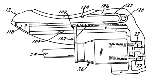
[0036] Figures 10 and 11 illustrate a cord retaining system 100 in
accordance with an altemative preferred embodiment of the present invention. A
retaining member 102 holds the power cord female plug head 26 engaged with
the AC power jack contact blades 22 in the power tool 12. The retaining member
102 slides in a track 104 of the housing 12a. The retaining member 102 has a
serrated top surface 116.
[Q037] Figure 12 illustrates a release member 106 in spaced apart
relation to the retaining member 102. The retaining member 102 has a
rectangular planar surface 108 and a perpendicularly extending yoke component
110. The yoke component 110 has an opening 112 large enough for the power
cord 24 to fit through but small enough to prevent the plug head 26 from
pulling
through the yoke 110. The yoke 110 has notches 114 that allow the retaining
component to slide on the tracks 38 (Figure 9) of the power tool housing 12a.
CA 02388726 2002-06-03
Attomey Docket No. 0275S-000429
The retaining member 102 has a serrated surface 116 formed on the planar
surface 108 thereof, rather than on an edge, as with the system 10 of the
first
described embodiment.
[0038] Wdh reference to Figures 11 and 12, the release member 106
has a release element 118 formed at one end and a pair of mounting members
120 at the other end. An upper portion 122 of the release member 106 in
contact
with wall portion 124 allows a lower portion 126 thereof to be continuously
urged
into engagement with the retaining member 102. Release member 106 is made
from plastic and has a degree of flexibility which allows the lower portion
126 to
be biased into constant contact with the retaining member 102 when the tool 12
is assembled. The mounting members 120 support the release member 106
from suitable recesses (not shown) in the power tool housing 12a.
[0039] The release member 106 has a serrated surface 128 that
engages the serrated surface 116 of the retaining member 102. When the
release element 118 is depressed, as indicated in Figure 11, it pushes the
serrated surface 128 of the release member 106 away from the serrated surface
116 of the retaining member 102. While it is held in this position, the
retaining
member 102 can be moved slidably away from the power jack 22.
[0040] The preferred embodiments described herein provide an easy to
use means for holding an electrical power cord secured to an AC power jack of
a
portable, AC powered tool. Advantageously, the embodiments do not require
any extemal tools or cumbersome procedures for securing or releasing the
power cord to and from an AC power jack. Furthermore, the preferred
~~
. . . . e-.il:~:i,..-; f I I =I -
CA 02388726 2002-06-03
Attorney Docket No. 0275S-000429
embodiments do not significantly add to the complexity of manufacture of the
tool
or increase significantly its cost, weight or overall dimensions. In addition,
the
preferred embodiments accommodate a variety of plug head shapes and sizes.
[0041] The description of the invention is merely exemplary in nature
and, thus, variations that do not depart from the gist of the invention are
intended
to be within the scope of the invention. Such variations are not to be
regarded as
a departure from the spirit and scope of the invention.
12