Note: Descriptions are shown in the official language in which they were submitted.
MOVABLE HUT
SPECIFICATION:
Field of the Invention
This invention relates to a fishing house or hut that is movable and formed of
an undercarriage of skis,
a tow-bar, platform base, folding back and front wall panels, a door in the
back wall panel, roof support
rods and sheet material. The hut can be moved whether in a folded, collapsed
position or in its fully
extended orientation.
Prior Art
Ice fishing huts being portable or movable have been devised and used for many
years. Mostly the huts
had to be small, very light in construction so that they could be transported
to the hunting or fishing
sights by manual labor. Some designs were developed restricted by the fact
that trails were few in
number and snow machines and all terrain vehicles were not there until these
latter years to provide the
power needed to pull elaborate folding structures through the mountains and
forest trails. A variety of
structures were invented that were either very small so they could be carried
or to heavy and bulky to
be pulled up hills through winding rough trails. This" Movable Hut" can be
moved in very little time
and with minimal inconvenience. The innovations incorporate
A suspension system that allows increased speed over rough trails unlike skids
that were solid and
increased the vibrations with speed and shifted equipment or the load to cause
damage to both load and
hut.
A folding hut that is unique in that all parts are interconnected to remain as
a single unit whether fully
deployed or in a collapsed orientation except for the five roof rods. This
reduces the risk of misplacing
parts and ensuring the right elements are in place while raising the
structure.
A steering system that allows maneuverability around sharp corners while being
towed offers
significant improvement over straight skids seen on other structures. It
allows for easy navigation
around obstacles and avoids tipping.
2
CA 02389102 2003-08-18
MOVABLE HUT
A semi-transparent re-enforced fabric allows available light to penetrate
unlike a solid material or
fabric.
A regular door re-enforced by double solid sheeting rather than the
conventional flaps as in a tent.
A shaped barn type roof of re-enforced fabric allows the natural elements such
as wind to shed any
snow accumulations on the roof of the hut in winter.
The stove and stovepipes are secured in such a way as to prevent fire damage
with the hut in a
deployed orientation.
Stabilizing skies that allow support to the outer floor of the hut while in
the deployed orientation and
while being moved to another location.
A cable system re-enforces all components of the hut against its external
climatic forces (wind and
snow) while deployed.
A sleigh in which the main hut structure is folded in the bottom in such a way
as to allow ample room
for supplies or furnishings.
The sleigh is strong enough to enable a machine to travel at normal speed
while in tow. Permitting the
users to be able to fish in comfort through the two fishing holes in the
interior of the hut especially
during cold weather.
The folding hut can be moved while in a deployed orientation.
3
CA 02389102 2003-08-18
MOVABLE HUT
The following searches were done on the CIPO database using a key word search
and each find was
compared against the Movable Hut application. None of the patents found
contained elements of the
Movable Hut application.
Shelter
2354840 1246826 1313447 568025
2339760 2100845 1096267 556170
2203093 1096743 1032053 542898
8-2177636 1056253 1030717 531025
1237624 2195549 1013916 529790
2348045 2103227 1009536 462253
2345398 1276520 974141 445494
2248896 1057879 956768 441418
2205354 2225864 905626 437075
2194691 2211964 897388 436455
2153513 1064800 880010 370732
2082465 1129754 867120 300286
2055031 1187972 870923 213636
2018294 2198067 731845 2336452
1290912 1278732 718144 1330414
1265307 1275608 706186 1207969
1187767 2011491 686103 2302137
2338439 2070270 681598 2262205
2283111 2152900 659372 2244174
2159825 1049370 654505 2242483
2103103 580600 653204 22211964
2085688 2365055 646968 2166039
1254812 2304359 625501 2101602
1249761 2040427 623836 2091387
2194338 2014364 594358 615722
2174150 1331334 582289 2081969
2002625 581860
Hut
1244214 2222397 1237624 577240
2081969 2115213 615722 575138
2225846 2047166 610721 556168
547404
Huts 711846 Fish Hut WinterNil
Fishing Huts Nil Tent Ice FishingNil
Hunting Huts Trailer tent 779159
2081969
Dwelling 1230213 Sleigh House Nil
926076 Fish Hut 2115213
903975
Ice Fishing Nil
Cabin
Ice Fishing Nil
Shanty
4
CA 02389102 2003-08-18
MOVABLE HUT
SUMMARY OF THE INVENTION
Inherent in known types of movable huts the uses for ice fishing or hunting
applications require that
supplies and other support items need to be carried in convoy to remote areas.
Consequently requiring a
lot of time and effort in deploying huts and partaking of the selected
sporting activity.
The movable hut can be configured for transport by one lone individual and is
able to carry all the
necessary supplies and support items the individual needs for an outing in a
single trip. At destination
once unloaded of supplies pulling a few select pins permit the individual to
change the movable hut
from its transport configuration to its deployed hut configuration. A wood
stove for heating and wind
proof ice holes at each corner of the hut for a leisurely day of ice fishing.
Fishing not very good. Then the individual may move the hut as is by
retracting the ice hole telescopic
tubes and move to another destination on the lake or river and reconfigure for
fishing.
The advantages of the movable hut are its ease of mobility, carrying supplies
and protection from the
elements for an enjoyable day of sporting activities.
Reference to the specifications provide more details on the Movable hut that
further describe the
configuration that permit a user of this hut to transport it and deploy it
easily with minimal amount of
time required and by a lone individual..
CA 02389102 2003-08-18
MOVABLE HUT
BRIEF DESCRIPTION OF THE DRAWINGS
The invention is made clearer through the following drawings and descriptions.
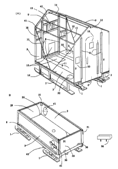
FIG. I
(A) Illustrates the movable hut without its reinforced covering so that we can
see the interior
parts of the hut, which is constructed within and in accordance with the
present invention.
(B) Illustrates the movable hut in the folded position with its two ends
attached to form a box
sleigh ready to receive interior furnishings and roof rods in preparation for
travel.
FIG. 2
(A) Illustrates the movable hut with its re-enforced covering permanently
secured to the front
and back walls except for the bottom edges of the outer platforms where the
covering is attached
by elastic cord or budge-cord to hooks on the underside of the outer
detachable support skis.
FIG. 3
(A) A view of the steering cross-member with a steering pin. Also showing is
the center
platform in which the folded back and front panels will rest.
(B) A spring loaded bolt and hitch allowing the hut to rock sideways as well
as absorb shock
while being pulled.
(C) Side view of the split cross-member for steering, the drawbar, the spring-
loaded swivel pin,
The channel iron to which the ski is attached as well as the steel frame
attached to the tow-bar.
(D) The drawbar and frame.
(E) Blocks to stop springing when placed between the skis and springs when the
hut is stationary
and fully extended.
(F) Shows the spring, ski, and channel iron and solid cross-member.
(G) Shows the platform support beams running crossways to the cross-members.
FIG. 4
(A) Illustrates the back of the hut with the door and panels folded into the
bottom center
platform. The side platforms with the outrigger skis attached are elevated
vertically. The two
6
CA 02389102 2003-08-18
MOVABLE HUT
ends of the box sleigh can be removed and used as tables.
(B) Shows the front box sleigh end and also the side platforms raised with the
outrigger skis
removed. The front center wall has been raised from the platform high enough
to allow the front
folded panel to hinge onto the top of the folded back panel.
(C) A top view of the center and side platforms with corner hinge pins.
Fishing hole locations are
shown.
(D) A horizontal view of the platforms with the outrigger skis in the support
position.
FIG. 5
(A) Illustrates the rear door, center and side panels
(B) Shows the front center and side panels with stovepipe.
FIG. 6
(A) Interior stove pipes going through a fireproof steel sheet with an exit
hole. A ring and rod
secure the pipes to the front wall panel with washers and butterfly nuts.
(B) Stove.
(C) Outside stove pipes with ring and rod to secure the pipes at a safe
distance from the wall
panel.
(D) Shows the roof and wall support rods.
(E) Metal stops are attached to the inside frame of the door.
(F) Rod ends with bolt locks for one end of the roof and wall panel support
rods. This allows the
pin to be retracted when inserting the rod and locked alter the pin is
inserted.
(G) A stationary pin at other end of rods.
(H) Metal plates with holes. When secured they re-enforce the corners of the
panels and accept
the roof rods and their bolts and pins.
(I) Metal plates for the very top of the front and back wall panels to accept
the rod pins and bolts.
eyehooks are attached to the plates to which a turnbuckle and cable are
tightened to retain the
wall to the rod.
Picture #1 on Page #27
(A) Show the Movable hut being drawn in its open Hut configuration to a new
fishing location.
7
CA 02389102 2003-08-18
MOVABLE HUT
Picture #2 on Page 28
(A) The roofing material shown at the top of the picture is a semi transparent
reinforced fabric
that covers part of the structure.
(B) Shows the arrangement of the roof rods.
(C) Show the interior of the Hut and the stove and stove pipe configuration on
the back wall with
protective fire sheeting
(D) Shows interior stovepipe fastened to back wall going through a protective
steel sheet that
joins the interior and exterior stovepipes.
(E) This picture also shows the reinforced framing around the paneling on the
back wall. Note
the framing is similar on the front wall.
(F) The piano hinges are clearly seen on each side of the stove where the
structure can be folded
in on itself.
8
CA 02389102 2003-08-18
MOVABLE HUT
DETAILED DESCRIPTION OF THE INVENTION
A movable folding hut for fishing and hunting consist of a foundation of four
skis with springs, which
absorb shock and also swivel independently to follow the contour of rough
trails. The back springs
swivel by means of a pin and block that is welded to a short piece of channel
iron bolted to a hardwood
cross-member. The front springs also swivel on a pin and block welded to a
longer piece of channel
iron and bolted to a movable cross-member. The movable cross-member acts as
the steering device by
means of a bolt through the center and through a stationary cross-member; a
layer of sheet metal on
each side and between these two cross -members and down the sides separated by
a washer reduce
friction and wear. The hut is towed by a drawbar, which is connected to an
angle iron frame. The frame
is welded to the for-mentioned channel iron bolted to the movable cross-
member. There are rubberized
bumper pads placed on the underside of the center platform where the nose of
the rear skis could come
in contact with the hut on rough trails. Four beams separated equally are
bolted and run lengthwise to
the cross-members and are covered with strong flooring making a central
platform. Pieces of material
the same length as the beams form a short wall that protrude high enough on
its edge to create a cavity
into which both front and back panels can fold. A piano hinge is attached to
the top edge of these raised
sides and attached to folding side platforms creating two outside raised
platforms. When the outside
platforms are hinged perpendicular to the center platform they create two
outside walls of a box sleigh.
Two end pieces are made which connect to these outside vertical wall by means
of door hinges with
pins to complete the box sleigh. These two end pieces can be used as tables
when not in use when the
hut is fully extended. The outside platforms must be half the width of the
center platform so as to
correspond with the front and back folding wall panels. The side platforms
when down have skis
attached to the outside edges and are secured by bolts with butterfly nuts to
make them easily
detachable and are there for three purposes, first to act as a brace to the
outside platforms when
extended, secondly to enable the hut to be pulled when completely erected and
thirdly to have hooks
attached by which to tie down the re-enforced covering by means of elastic
rope. These side platforms
have each one fishing hole cut in with covers to fit. The corners of the side
platforms also have half
door hinges in the perpendicular position connect to the opposite half hinges
attached to the box ends
by means of hinge pins which secure the sides of the box for travel and
secondly when in the horizontal
position connect to another set of opposite half hinges by the same pins to
the outside bottom corners of
both the back and front outside panels securing the outside panels to the
outside platforms. The back
9
CA 02389102 2003-08-18
MOVABLE HUT
wall consists of three panels attached to each other by piano hinges. The
center panel is twice the width
of the outside panels and equal in width to the inside recessed platform. This
center panel also contains
the door. The door is paneled on both sides for strength and is also hinged by
a piano hinge. The
outside back panels are equal in width to the elevated outside platforms. They
hinge outwardly and fold
onto the inside panel. Hinges attached to the center platform at the bottom
and on each side of the door
enable the back wall to again fold inwardly into the length of the cavity of
the inside platform. The
front wall is similar except the outside front wall panels are hinged inwardly
to fold onto the front
center panel which in turn by means of an elevated piano hinge from the center
platform allows the
front wall to fold down to rest on top of the back wall and fill the center
platform cavity. The length of
the center platform must always be longer than the height of the back or front
walls so as to allow them
to fold into the cavity of the center platform. The front and back wall panels
including the windows and
door openings have their inside edges all reinforced by edging material that
is glued and screw nailed
for a stronger structure. The front and back walls are held apart by means of
rods with pins on one end
and bolt type locking pins on the other end. Metal plates are made to fit the
top center and top corners
of the back and center panels and also the outside top corners of the outside
back and front panels. Each
plate is securely attached and drilled to accept the pins of the rods. A cable
is attached to hooks and
turnbuckle at the bottom of the center plates and when tightened hold the
center panels solidly against
the rods. Similarly cables with turnbuckles are attached to eyes on the
corners under the outside rods
down to hooks placed near the center and edge of the outside platforms. These
cables when tightened
also hold the outside panels against the outside rods as well as helping to
support the outside platforms.
The roof and sides of the hut are covered by re-enforced semi transparent
fabric which is attached to
the outside edges of the top and also outside edges of the front and back
outside wall panels by staples
and re-enforced by means of screws and strapping. The re-enforced fabric over
the roof is supported by
the rods which are set at such an angle so as to easily shed snow or rain. The
bottom edges of the re-
enforced fabric have eyelets, which are then traversed by budge-cord, which is
attached to the hooks on
the underside of the frame holding the outer support skis. The rods, cables,
corner hinges and fabric
covering all contribute to an extra strong hut needed to withstand snow, rough
trails, wind and the
weight of persons occupying the hut. Four hardwood blocks are made to fit
between the springs and the
skis when the hut is extended and stationary to eliminate any springing
motion. A budge-cord with a
hook is connected to the top inside of the door by means of an attached eye
and the other end clamped
to the center of the center left roof rod creating a door closer. A strap is
attached to the door as a door
CA 02389102 2003-08-18
MOVABLE HUT
handle that will not interfere with the folding of the hut. Thin metal sheets
cover the floor under the
stove and back wall so as to fireproof the hut from the heat of the stove. The
stove is attached to a
plywood base for travel when placed into the sleigh so as not to move around
while the hut is in the
folded position. The stove is removed from this base when the hut is extended
and secured to the center
floor. An inside stove pipe is attached to the stove and the other end with an
elbow goes through a fire
proof metal square in the front wall and is secured there by a ring and rod
attached to the front wall
with butterfly nuts and washers. The outside pipe also with an elbow goes up
the back wall and clears
the roof fabric and also is held securely by a ring, rod, nuts, washers and
butterfly nuts securing the
pipe at a safe distance from the wall. Tapered tubes of the same diameter as
the holes in the outside
floors are placed between the ice and the floor panels directly over the ice
hole and the others are
placed from within the hut through the cut floors. This joins the first tube
in a telescopic manner
creating a seal that prevents cold air from entering the movable hut while
fishing.
11
CA 02389102 2003-08-18
MOVABLE HUT
DESCRIPTION OF THE PREFERRED EMBODIMENT
With reference to the drawings and in particular to Fig. 1 thereof a new and
improved movable house
or hut for hunting and fishing embodying the principles and concepts of the
present invention.
In Fig. I (A) and Fig. 2 (A) there is shown components of the movable hunting
and fishing house or hut
in the deployed orientation. This invention is collapsible FIG. I (B) and can
be pulled in this position or
can be pulled in the deployed orientation FIG. 1 (A) and FIG. 2 (A).
The movable house or hut of the present invention includes six major
components,
( 1 ) The undercarriage including the support structure. FIG. 3 (G), FIG. 4
(D)
(2) The steering, frame and tongue Fig. 3- (A), (B), (C) and (D).
(3) The housing base FIG. 4 - (A) (B) (C) (D)
(4) The back wall panels including the door FIG. 5 (A) and front wall FIG. 5-
(B)
(S) The roof support. FIG. 1, (A), (# 9)
(6) The sheet material FIG.2 - # 17
The undercarriage of the structure is made up of the following:
Four skis with springs attached (# 1 ) which swivel up and down by means of
single bolts through the
leaf spring couplers # 53 and through the stationary couplers # 52 that are
welded to channel irons # 26.
of which two are bolted to the back cross-member # 24 and two are bolted to
the front cross-member #
54. There are rubberized bumper pads # 62 placed on the underside of the
center platform where the
nose of the skis could came in contact with the hut on rough trails. Beams #
35 separated equally are
attached to and run crosswise to the cross-members #24 and # 25 and of a
length determined by the
height needed for head room from the center platform (# 4) to the peek of the
roof structure so as to
accommodate the folding back and front wall panels.
The angle iron steering frame # 23 is welded to the front channel irons # 26
and a steel draw bar # 19 is
bolted to it in such a manner as to allow the draw bar to rock up and down
against the solid steering
frame # 23. The triangular draw bar (# 19) is re-enforced by means of a steel
crossbar and corner plates
FIG. 3 (D). The hitch # 22 illustrates a long spring loaded bolt to absorb
shock penetrating a steel block
welded to the draw bar enabling the hut to swivel clock and counter clockwise.
The for-mentioned bolt
is then welded to a double plate having drilled holes to accept a draw pin (#
18). This allows the hut to
CA 02389102 2003-08-18
MOVABLE HUT
be coupled with a vehicle. The front cross-member # 54 is covered on the top
and sides with steel
sheeting # 45 and attached by screw nails to the sides. A large steel washer #
57 separates cross-
members # 54 and # 25. Steel sheeting # 45 also covers the undersides of # 25
as were # 54 so as to
reduce friction and wear. The large washer # 57 is traversed by a steering
bolt # 58 which passes
through both the centers of the two front cross-members # 54 and # 25 allowing
the steering of the hut
around sharp corners when being pulled through narrow bush trails. The hut can
be pulled with the
draw bar # 19 in the collapsed orientation or deployed orientation.
FIG. 4 illustration (C) the housing base, is a sheeted central platform (# 4)
that cover the overall width
and length of the beams # 35(Fig. 4 illustration (A)) run crossways to the
cross-members shown in# 24
(Fig #3 (F)) and # 25 (Fig #3 (C)), two pieces of material form a short wall
running the outside
perimeter of the base # 37 (Fig #4 (A)) on its outside edge approximately
three quarters of an inch
thick, the length of the platform and high enough to form a depression to
receive the folded front and
back panels. The raised sides are attached securely to the outside beams # 35.
A piano hinge is attached
to the top edge of these raised sides # 37 to connect to two outside platforms
(# 3) which have been re-
enforced by strapping # 51 along the outside edges and ends. Fishing holes #
32 have been cut at
opposite ends of the outer platforms (# 3). The fishing holes each have
fitting covers # 61. The fishing-
hole covers #61 facing inwards have steel tabs attached to them to prevent the
covers from dropping
through the holes. Carriage bolts go through the center of the covers and
through the center of outside
cross- members, which are of a length greater than the diameter of the hole.
The bolts are tightened
using butterfly nuts with washers to hold the covers rigid.
A half door hinge # 31 is located at each corner of the outside platforms (#
3). These half hinges # 31
will later be used to connect both the outside platforms (# 3) and half hinges
on the bottom corners of
the outside back and front wall panels (# 5) as well as connect the elevated
outside platforms # three to
a perpendicular position to the other half hinges on the corners of the front
# 30 and rear # 29 box ends.
Two cable hooks # 55 are located near the center outside edges of platforms (#
3). Two outrigger
support skis (# 2) are connected to a frame made up of three posts (# 7) and a
connecting stringer (# 50)
of the same size material running along the outside and under the edge of the
outside platforms (# 3).
The three posts (# 7) located at equal distances from each other are re-
enforced by wall type brackets #
16 located inside of each outside post above the ski and screw nailed to the
top side of the support skis
16
CA 02389102 2003-08-18
MOVABLE HUT
and the posts. Brackets # 16 are located opposite and inversed to each other
on either side of the center
post and one being screwed to the underside of platforms (# 3) and the post
the other screwed to the
post and top of the ski (# 2). Four carriage bolts with washers and butterfly
nuts (# 33) are needed on
each side and spaced equally to secure the frame (# 50) to the outside
platforms (#3).
The back wall consists of three separate panels having their inside edges re-
enforced by strapping,
which have been glued and screwed for added strength. The center panel (# 56)
is twice the width of
the two outside panels (# 5) which also contains the door (# 6) which is
paneled on both the inside and
outside and re-enforced by strapping that has been glued and screwed around
the inside edges. The
outside edges of the door opening are strapped, glued and screwed for
strength. The door has a
Plexiglas window (# 10) also re-enforced with strapping, glue and screw nails
around the edges. A strap
(# 21 ) is used as a door handle. The door swings open on a piano hinge (# 8).
The center panel can fold
onto the center platform by means of a hinge placed on each side of the door
(# 6) at the bottom and
inside of the center panel (#56). The hinges are further re-enforced by metal
plates attached by screw
nails to the strapping at the bottom edge of the door opening and bottom edge
of the center panel. Bolts
secure the hinge to the center platform (# 3) and through the metal plates and
center panel #56 on each
side of the door for added strength. There are two metal channel clips # 36
screwed into the back edge
of the center platform on each side of the door opening which are used to
secure the back box end (#
29). Similarly two more metal channel clips are located on the front edge of
the center platform to
retain the front box end (# 30). The outside wall panels have a half door
hinge (# 31 ) at each of the
outside corners which connect to its other half hinge located at the outside
corners of the platforms (#
3) using hinge pins. The outside panels (# 5) of the back wall can fold
inwardly by means of piano
hinges (# 8) to rest on the center panel (# 56). The center panel (# 56) can
now fold down into the
cavity of the center platform (# 4). Three stops (# 40) are screwed equal
distances apart to the strapping
of the door frame opposite the door hinge and are protruding into the door
entrance in order to stop the
door (# 6) from swinging through the door opening. The outside wall panel has
a Plexiglas window
(# 10) able to slide open for ventilation FIG. 5 A.
The front three panels in FIG. 5 B are of the same dimensions as FIG. 5 A but
has the following
changes:
17
CA 02389102 2003-08-18
MOVABLE HUT
The two outside front panels # 60 using piano hinges fold inwardly to rest
against the front center panel
# 59 ready to be folded down to the top of the back panels # 56 and (# 5)
resting on the center platform
(# 4). In order for the front center panel # 59 and its folded front outer
panels # 60 are able to
accomplish this, the front bottom edge of the front center panel # 59 is
shortened to accommodate a
crosspiece # 34 attached to the front edge of the center platform (#4) and
elevates the piano hinge (#
8), that is screwed to the top inside edges of the cross piece and to the
inside strapping of the bottom
edge of the front center panel (# 59) high enough to allow the front panels (#
60) to fold inwardly and
lay flat on top of the back panels (# 56) and (# S) laying on the center
platforms. A sliding Plexiglas
window (# 10) is located on the top right side of the front center panel FIG.
5 B allowing for
ventilation. Another sliding Plexiglas window (# 10) is located in the center
of the outside panel. The
openings have grooved pieces of strapping that are screwed and glued to the
top and bottom of the
opening allowing the Plexiglas window to slide. There are two pieces of
strapping attached horizontally
across the front center panel with glue and screws Fig. 5 B and wide enough
apart to have a piece of
sheet metal with a stove pipe hole in it (# 13) able to distance the stove
pipe from flammable material.
The outside stovepipe (# 49) is secured to the front center wall panel by a
steel ring around the pipe
welded to a threaded rod (# 48) keeping the pipe a safe distance from the wall
of the hut. A washer and
standard nut on the threaded rod outside of the panel and washer and a
butterfly nut on the threaded rod
inside the panel makes the pipe secure when tightened and also allows for easy
removal. Similarly the
inside stove pipe (# 47) and ring welded to a threaded rod (# 46) are secured
in the same way to keep
the pipe at a safe distance from the wall panel and secure when moving the
hut.
The roof support consists of five rods (# 9). Each rod has a bolt and lock
device (# 39) at one end and a
stationary pin (# 38) at the other. The bolts and pins are made to enter the
holes in plates (# 41 ) and
plates (# 42). The plates (# 41 ) are located at the top outside corners of
the front (# 59) and back center
panels (# 56) and the outside corners of the outside front (# 60) and back
outside panels (# 5). The
plates (# 42) of which there are two are located at the top center of the
center wall panels. The rods are
inserted into the plates with the stationary pin first and then with the bolt
retracted are lined up with the
opposite plate holes and then inserted and locked. The front top plate (# 42)
has an eyehook attached to
which a cable (# 14) is attached and secured by cable clamps. The other end of
the cable is connected to
a turnbuckle also by cable clamps. The turnbuckle has one end made into a
hook, which is then hooked
into the opposite top plate by means of a drilled hole in the base of the
plate. When the turnbuckle is
tightened, the center panels are drawn into the rod ends securely. The outside
panels are drawn to the
18
CA 02389102 2003-08-18
MOVABLE HUT
ends of the rods by means of turnbuckles attached to eyes under the plates (#
41 ) and cables (# Ii) to
hooks (#55) located near the center edge of the outside platforms by cable
clamps. These cables help
support the outside platforms as well as retain the outside wall panels
against the rod ends when the
turnbuckles are tightened.
Two eye hooks (#12) are bolted to the peak of the hut, the eye facing to the
outside and the bolt end
going through plates (#42), are secured by a washer and nut. A rope is
attached to each eye making it
easier to raise the front and back center panels (#56) and (# 59).
The sheet material is a re-enforced semi-transparent fabric (# 17), which
allows light to penetrate.
Fabric (# 17) is attached to the top outside edges and also the outside edges
of the front and back
panels. The fabric is further re-enforced by screws and light strapping (#
50). The bottom edges of the
fabric have eyelets that are traversed by budge-cords (# 27), which attach to
cup hooks on the underside
of the frame (# 50) held up by support posts (# 7) and outrigger skis (# 2).
19
CA 02389102 2003-08-18
MOVABLE HUT
The use and operation of this invention through the above descriptions should
be rather clear and no
further explanation will be provided to this end.
The optimum dimensional relationships for the parts of the invention include
variations in size,
materials, function, shape, form and manner of operation, assembly and use are
intended to be
encompassed by the present invention
The above descriptions should be considered as illustrative only of the
principles of this invention.
It is not desired to limit the invention in the above descriptions to the
exact construction and operation
of the invention as shown. Therefore all modifications that are suitable and
equivalents may be resorted
to within the scope of this invention.
CA 02389102 2003-08-18