Note: Descriptions are shown in the official language in which they were submitted.
WO 01/32090 CA 02389221 2002-04-25 PCTIUSOO/21677
1
METHOD AND APPARATUS FOR
MONITORING CRYOSURGICAL OPERATIONS
BACKGROUND OF THE INVENTION
The field of the invention is the measurement of the effects on tissue
during cryosurgical operations, and more particularly, the depiction of frozen
tissue during such operations.
The primary use of cryosurgery is to ablate tissue in situ by the
application of extreme cold to the tissue. Cell death results and the dead
cells typically slough. This process is referred to as "cryonecrosis". The use
of cryonecrosis procedures has distinct advantages over other surgical
methods including: little or no bleeding; lessened need for anesthesia; faster
recovery time; lack of scarring; and preservation or selective alteration of
structural components of tissue such as collagen. The cryonecrosis
procedures lend themselves well to minimally invasive surgery such as
percutaneous, endoscopic, and endovascular surgery. They also can be
performed more frequently on an out-patient basis, and can be performed on
high-risk patients who could not withstand traditional surgery.
Cell death is achieved in cryosurgery through the removal of heat by
application of extremely cold temperature, either directly to the tissue, as
in
the application of a swab or spray of liquid nitrogen to the skin, or through
contact with a very cold instrument, the "cryoprobe". Cryoprobes such as
those described in U.S. Pat. Nos. 4,946,460; 348,369; 5,334,181; 5,916,212;
4,483,341, typically are powered by liquid or gaseous coolants or a mixture of
both. In a typical application, nitrous oxide is delivered to an expansion
chamber within the tip of the cryoprobe, where extremely cold temperatures
result from the Joule-Thompson effect. The cold temperatures spread to the
tip and then to the surrounding tissue.
Heat is extracted from the surrounding tissue in a "heat sink" effect.
The tissues freeze first at the surface of the cryoprobe, and an "ice ball" of
frozen tissues grows outward from the cryoprobe surface as the heat is
extracted. Although this ice ball may be seen, either with the eyes or through
medical imaging systems, the boundaries of the ice ball do not accurately
measure the region of cryonecrosis. A long-standing problem in this art is the
WO 01/32090 CA 02389221 2002-04-25 pCT/US00/21677
2
accurate detection and depiction of cell death so that the surgeon can control
the cryonecrosis procedure.
The measurement of tissue temperature (thermometry) is an accepted
method of predicting cryonecrosis. However, thermometry has severe
shortcomings. The cryonecrotic range of temperature is wide, imprecise, and
variable from tissue to tissue. It is well known that cryonecrosis can occur
at
temperatures considered as non-lethal. On the other hand, some tissues are
very cryoresistant. Due to this uncertainty, "overkill" is usually built into
cryosurgical procedures. The usual recommendations for a standard
destructive cryosuCgical application, when addressing a cancerous Iesion for
example, are quick freezing, slow thawing, and repetition of this
freezing/thawing cycle until a tissue temperature at least -40 degrees Celsius
is measured at the lesion boundary. When this is done, the visible ice ball
extends well beyond the boundary of the lesion. Furthermore, tissular
thermometry is an invasive method, requiring the insertion of measuring
devices, usually in the form of thermocouple needles. The cryoprobe itself
provides no information on the temperature of the surrounding tissue and
temperature measurements provide only point-specific information. Methods
such as those described in U.S. Pat. Nos. 5,433,717 and 5,706,810 have
been proposed for producing temperature maps using magnetic resonance
imaging (MRI) systems, but such methods are very expensive due to the high
cost of the MRI system.
Other methods have also been proposed for predicting cryonecrosis,
but all of these image the boundary of the ice ball and do not detect the
region inside the ice ball where cell death actually occurs. Such known
methods as heat flux measurements, CAT scanning, sonography, therefore
exaggerate the boundary in which cell death occurs.
Another such method is bioelectrical impedancemetry which measures
the electrical impedance of the ice ball. Close correlations have been found
between the impedance of the ice ball and the cryodestructive tissue
temperatures. As described in U.S. Pat. No. 4,252,130, when a certain
amount of heat is extracted from a biological system, there is a change of
phase or change of state which converts the freezable water into ice and has
CA 02389221 2002-04-25 Pun,s O O, 2167 7
IPEAIUS 2 5 MAY 2001
3
the result of "extracting" from the cell the water of solvation and the
=structural" water, in particular the membranous water. Since the stability of
a
biological system is dependent on the maintenance of an exact concentration
of aqueous solutions, the consequences of the loss-of water in the crystalline
-
structure of newly formed ice is substantial.
Impedancemetry or bioelectrical tissue impedance measurement detects the
moment water freezes as an increase in electrical impedance of the tissue. At
least two
electrodes are employed to measure the impedance across the target tissues
(e.g. a tumor)
and to provide an indication to the surgeon when that impedance suddenly
increases.
Such prior impedancemetry methods have some of the shortcomings of thermometry
in
that their ability to accurately predict cryonecrosis was limited. In
addition, as exemplified
by U.S. Pat. Nos. 4,140,109 and 4,306,568, many prior procedures are invasive
in that
they require the implantation'separate needle electrodes or other sensors.
SUMMARY OF THE INVENTION
The present invention is a method and apparatus for measuring ice
ball production and growth in 6 biological medium such as tissue during a
freezing procedure such as cryosurgery. More particularly an electrical model
of the ice ball is established which relates the size of its eutectic zone to
its
complex impedance, the complex impedance of the ice ball is measured
during the freezing procedure, the size of the eutectic zone is calculated
using the electrical model and the measured complex impedance, and the
size of the calculated eutectic zone is visually indicated.
The present invention enables one to image in real-time the growth of
the ice ball and the eutectic freezing zone around a cryoprobe or a sensor in
contact with the target tissue, during a cryosurgical procedure. As a result,
one can predict the area of tissue destruction, in both surface as well as in
depth, around the cryoprobe. The surgeon can thus control manually or with
computer assistance the necessary power and duration of a cryosurgical
application to achieve a precise and selected destructive area around one or
more cryoprobes.
AMENDED SHEET
CA 02389221 2002-04-25 PcTlos o o / 216 7 7
IP~".~,~S 2 5 MAY ZOOi
4
The present invention also enables the surgeon to visualize and to
control the operation in locations where it is difficult or even impossible to
see
the ice ball (e.g., endoscopy, minimally invasive surgery, endovascular
surgery). An image of the forming ice_ball is produced on a monitor and may
be registered with a previously acquired anatomic image o r anatomic images
acquired during the operation using ultrasound, x-ray CT or MRI systems.
There are situations when more than one cryoprobe is used, for example, an
irregularly shaped and/or large lesion. In such instances, several cryoprobes
must be used to cover the entire volume with overlapping ice balls. These
probes
work simultaneously for cumulative heat sink effects and to expedite the
procedure.
In such procedures, each cryoprobe develops an ice ball towards the outer
margin
of the lesion until it encompasses the lesion while simultaneously tending to
grow
inwardly to overlap the margins of the other expanding ice balls. However, it
is more important to monitor the change of phase at the margin of the lesion
because it is the region where the lesion usually grows and where the
vasculature
supports its expansion. Also, the amount of healthy tissue destroyed, outside
the
lesion, should be kept to a minimum.
In some instances, 12 microcryoprobes can be used to better match the multiple
ice ball shape and volume to the lesion shape and volume. Each probe is
equipped with electrical connections and sensors to record data necessary to
construct and display, in real time, the image of the destructive area and the
sub eutectic area. Each probe is located in the lesion at an optimal distance
from the other. This distance is derived from the specifications referring to
its power, stated as the ability to change the phase of a certain volume of a
standard electro conductive biological medium in a designated time.
Since the freezing process is slow in these large and/or irregularly shaped
lesions, in the nature of 5 minutes to 20 minutes, it is possible to use a
dispatching
apparatus. Such a dispatcher permits automatic recording, at intervals of 0.25
or 0.5 second, the data at each electrode/cryoprobe This data is continuously
collected to construct an image of the destruction based on the spatial
relationship
of the probes to each other.
The invention may also be integrated into a complete computer aided
operation. The invention may be used for the purpose of simulation of
different
operative conditions, in order to train and guide surgeons. The registered
computerized images provided by the invention may be compared with the pre or
AWttioFD SHEET
CA 02389221 2009-04-14
78943-3
4a
per operative images of the lesion, and the information used to control the
placement and operation of the cryoprobe.
In accordance with one aspect of the present invention, there is
provided a method for monitoring the progress of a cryoprocedure, the steps
comprising: (a) establishing an electrical model of an ice ball produced by
the
cryoprocedure which relates the size of a eutectic zone therein to the complex
impedance of the ice ball; (b) measuring the complex impedance of the ice ball
during the cryoprocedure; (c) calculating the size of the eutectic zone using
the
measured complex impedance and the electrical model; and (d) displaying an
indication of the eutectic zone size.
In accordance with another aspect of the present invention, there is
provided system for monitoring a cryoprocedure performed on tissue, the
combination comprising: a sensing electrode having a conductive surface in
electrical contact with the tissue; a remote electrode connected to conduct
current
passing through the tissue and the sensing electrode; an impedance processor
having inputs connected to the sensing electrode and the remote electrode and
being operable to produce an alternating current through the tissue and
measure
the complex electrical impedance thereof; a generator which produces the
alternating current; an amplitude detector which measures the voltage between
the two electrodes; a phase detector which measures the phase of the voltage
between the two electrodes; and computer means connected to receive the
measured electrical impedance from the impedance processor and being operable
to produce an indication of the eutectic boundary of an ice ball formed in the
tissue
by the cryoprocedure.
The foregoing and other objects and advantages of the invention will
appear from the following description. In the description, reference is made
to the
accompanying drawings which form a part hereof, and in which there is shown by
way of illustration a preferred embodiment of the invention. Such embodiment
does not necessarily represent the full scope of the invention, however, and
reference is made therefore to the claims herein for interpreting the scope of
the
invention.
CA 02389221 2009-04-14
78943-3
4b
BRIEF DESCRIPTION OF THE DRAWINGS
Fig. 1 is a schematic representation of an ice ball produced in tissue
by a cryosurgical procedure;
Fig. 2 is a schematic representation of an ice ball formed around a
cryoprobe;
Fig. 3 is an electrical model of the ice ball depicted in Fig. 2;
Fig. 4 is a circuit diagram of a complex impedance measurement
system;
Fig. 5 is a block diagram of a preferred cryosurgical monitor system
which employs the present invention;
Figs. 6, 7 and 8 are cross sectional views of three preferred
cryoprobes for use in the system of Fig. 5; and
CA 02389221 2002-04-25
WO 01/32090 PCT/USOO/21677
Fig. 9 is a pictorial representation of one embodiment of the
information displayed on a monitor which forms part of the system of Fig. 5.
GENERAL DESCRIPTION OF THE INVENTION
During cryosurgery, "freezing", i.e., crystallization of tissue, results from
5 the creation of temperature gradients in the tissue, due to the extraction
of
heat by the cryoprobe. The crystallization is observed in various
intratissular
fluids. These include the intracellular fluid (within the cells); the
extracelluar
fluid (between the cells); and the vascular fluid (consisting of the
microvasculature qf the tissue). At any point in time, the zone around a
cryoprobe can be characterized by the zones in which complete ("eutectic")
and incomplete ("pre-eutectic") freezing has occurred with respect to these
fluids. We sometimes refer to eutectic freezing as "dry ice" and pre-eutectic
freezing as "wet ice".
The different zones in an ice ball produced in tissues is depicted
schematically in Fig. 1. In this exampie, cold is applied with a probe 10 in
the
center of the ice ball. A first region 1 at the center indicates the zone in
which
complete intracellular crystallization has occurred. A surrounding second
region 2 indicates the extent of incomplete intracellular crystallization and
the
region contained within zones 1 and 2 has complete extracellular
crystallization. The next region 3 indicates a surrounding zone in which
incomplete extracellular crystallization occurs and the outer boundary of this
zone 3 is the visible ice front. And finally, a fourth region 4 is a zone in
which
tissue temperature is lowered (i.e. hypothermia).
We have discovered that eutectic freezing of the extraceliular fluids
includes eutectic freezing of the vascular fluids. We also have discovered
that eutectic freezing of the vascular fluids results in thrombosis
("cryothrombosis") of the microvasculature. Finally, we have determined that
thrombosis of the microvasculature results in celi necrosis within a matter of
hours. We have concluded, therefore, that eutectic freezing of the
extracellular fluids is predictive of cryonecrosis and a measurement of
extracellular fluid eutectic freezing is a measurement of the extent of
cryonecrosis.
CA 02389221 2002-04-25 PCT/US 0 0/216 7 7
IPEWS 2 5 MAY 2001
6
From these discoveries, a"two phase" physical model can be
constructed, showing the geometric form of the boundary of the ice ball, and
the boundary of the region of complete extracellular crystallization. Fig. 2
illustrates this model, where a cylindrical cryoprobe 10 having a
hemispherical
tip 11 produces an ice b-all 12 in the tissues which surround it. The boundary
14 of the ice ball 12 is the outer boundary of a pre-eutectic zone 16 where
extracellular fluids are partially frozen. A boundary 18 hidden inside the ice
ball 12 defines the outer boundary of the eutectic zone 20 where complete
extracellular freezing and delayed cell death occur. The present invention
measures and displays this eutectic zone boundary so that the destructive
cryogenic procedure can be accurately controlled.
The measurement of ice ball formation is performed using an improved
bioelectrical impedance measurement method. Biological tissue behaves as
an electrolyte that can be characterized in terms of its resistance and
capacitance.
It is well known that the resistance of tissue increases when it is frozen.
The same
is true with the altemating impedance of tissues, at least when measured at
relatively low frequencies, for example, from 500 to 5000 Hertz. Thus,
measuring impedance modulus in a biological medium or tissue has been
proven valuable in detecting eutectic crystallization. But this measure when
20 obtained through needle electrodes or through cryoprobes inserted into the
tissue is not able to give the operator a precise appreciation of the growing
eutectic zone inside the ice ball.
To practice the present invention an electrical model of the ice ball is
presented which relates the dimensions of its eutectic zone to its electrical
25 characteristics. The electrical characteristics are then measured using a
properly placed sensing electrode and a remotely located electrode. The
complex impedance is measured between these two electrodes at one or
more frequencies, and from these measurements and the electrical model the
dimensions of the eutectic zone within the ice ball can be calculated.
Referring particularly to Figs. 2 and 3, one preferred electrical model of
the ice ball represents the eutectic zone 20 as a lumped resistance Ro
connected in parallel with a lumped capacitance Co. The pre-eutectic zone
16 and the medium (i.e. unfrozen tissue) are modeled as a lumped resistance
AMENDFII currr
CA 02389221 2002-04-25
WO 01/32090 PCTIUSOO/21677
7
R, connected in series. The complex impedance Z (modulus Z, argument Z)
of this model is
OcosB= R , + R, (1)
1 , to
IZI sin 8 = I R ro to (2)
where: to = RoCow; w=2rrf; and f=frequency.
Given that in a homogenous medium RoCo=poco, then to=poEow, where
eo is the susceptibility and po is the resistivity of the medium. The value of
Ro
can thus be computed, and from this value one can calculate the eutectic
zone dimensions using formulas that relate the eutectic zone shape that is
produced by the particular probe that is used.
R = IZI sinB 1 ` (3)
t
R, =1ZI cose- sinto6 (4)
For example, when using the cylindrical, closed-end cryoprobe 10
having diameter do the assumption is made that the boundaries 14 and 18 of
the zones 20 and 16 are cylindrical along the length 10 of the
cooling/electrode
portion of the cryoprobe 10, and they are hemispherical over the end of the
cryoprobe 10. The electrical susceptibility of tissues in the eutectic zone 20
is
co and its resistivity is po. The equation relating the calculated resistance
Ro
to the diameter (d) of the eutectic zone boundary 18 is as follows::
1/Ro = 2Tr/po[Vlogn(d/do) + do/2(1-do/d)] (5)
The susceptibility and resistivity values Eo, and po are given the following
experimentally determined initial values:
WO 01/32090 CA 02389221 2002-04-25 pCT/US00/21677
8
co = 2x10-'' farad/cm
po = 8x10' ohm cm.
Variations in these values may occur over time due to changes in the
temperature and crystalline structure of the frozen medium. It is a further
aspect of the present invention that the measurement of complex impedance
at several frequencies enables the calculation of to(w) resulting in a better
determination of the eutectic zone dimensions. After measurement at two
frequencies, w and w', poeo is calculated as follows:
to(r.)) Z(t~')sin9(w')- Z(r~)sinB(w) (6)
Po6o= '
Z(w)sinB(w)- w Z(w')sinB(w')
This value is thus continuously measured and updated throughout the
measurement procedure to improve the accuracy of the calculations in
equations (3) and (4).
Other electrical models are possible and the calculations relating the
..,
electrical model to ice ball dimensions will also differ as a function of
cryoprobe shape. For example, the pre-eutectic zone 16 and the medium
may also be modeled as a resistance element R, connected in parallel with a
capacitance element C. The cryoprobe end 10 may be flat rather than
hemispherical or it may be an open sleeve that cools at its distal end.
To monitor the growing eutectic zone the electrical impedance is
repeatedly measured during the cryosurgical procedure. Referring to Fig. 4,
the measurements are made with a frequency generator 26 which produces a
sinusoidal voltage of amplitude Afef and phase cp,ef at the chosen frequency
f.
This voltage is applied through a known resistor Rfe, to an electrode 28 on
the
cryoprobe 10 and circuit ground is connected to a remote electrode 30. The
voltage VOUT is measured across the electrical impedance Z between the two
electrodes 28 and 30. The amplitude (AouT) of the measured output voltage
VOUT as well as its phase (cpouT) are determined and used to calculate the
complex values of the impedance Z.
CA 02389221 2002-04-25
WO 01/32090 PCTIUSOO/21677
9
Zmagnaude = JZJ= RRefAau~ (1 + Aout - 2Aovt cos¾ouf )' (7)
Zong(e - e = ATcta71[siTloout (='4out - cos 0out )-' J (8)
The complex values of the impedance can be measured at a number
of frequencies, and the resistancVR; of the pre-eutectic zone 16 and the
resistance R. and capacitance Co of the eutectic zone 20 are calculated using
equations (3) and (4) and:
Co=to/Row (9)
The dimension of the eutectic zone is then calculated using equation (5) and
the results displayed.
DESCRIPTION OF THE PREFERRED EMBODIMENTS
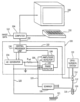
Referring particularly to Fig. 5, a system for monitoring a cryosurgical
operation includes an impedance measurement unit 100 that produces an
impedance signal at output 102 for a computer 104. The computer 104 is
programmed to process the impedance signals as will be described in more
detail below to calculate the dimensions of the ice ball produced around the
tip of a cryoprobe 106. These dimensions are used to produce an image on
display 108 that may be viewed by the surgeon and used to control the
- operation of a cryosurgical system 110. In the preferred embodiment
computer 104 receives real-time digital image data at input 112 which depicts
the anatomy being treated. Such image data may be produced, for example,
by an x-ray CT, ultrasonic or MR imaging system (not shown in the drawings)
that delivers fully reconstructed 2D images at a desired frame rate. These
images also contain markers that locate the freezing tip of the probe 106
therein, and the computer 104 produces an image of the eutectic zone that is
registered on the displayed anatomic image using these markers. The image
of the eutectic zone is sized in response to the impedance data received from
the impedance processor 100 and it grows in real time as the cryosurgical
WO 01/32090 10 PCT/US00/21677
procedure progresses. The image of the eutectic zone may overlay the
anatomical image, or it may be blended therewith to become semi-
transparent so that the underlying anatomy (e.g. tumor) can still be seen.
The cryosurgical system 110 may be any one of a number of
commercially available systems such as that disclosed for example in U.S.
Pat. No. 5,334,181. The system 110 provides a cold cryogenic liquid that
flows through a duct 112 to the cryogenic probe 106 when a valve 114 is
opened in response to a trigger signal manually initiated by the surgeon. The
cryogenic fluid flows out the end of the duct 112 and cools the tip of the
probe
106.
The conductive material of the cooled tip of the cryogenic probe 106 is
a sensing electrode 116 that is in intimate contact with the surrounding
tissues from which heat is extracted. This sensing electrode 116 is
electrically connected to one input of a scanner 118 that selects one of three
such input signals and applies it to through line 120 to the impedance
processor 100. The scanner 118 enables up to three sensing electrodes 116
to be monitored during the procedure.
A remote electrode 121 also connects to the impedance processor 100
through line 122. The remote electrode is attached to the skin of the patient
being treated and makes good electrical connection therewith. AC current
flowing between the sensing electrode 116 and the remote electrode 121
flows through the ice ball being formed at the tip of the cryogenic probe 106.
Impedance changes in the ice ball affect both the magnitude and phase of
this current and it is these changes that are measured and processed by the
impedance processor 100.
The impedance processor 100 is operated by a central processor unit
130 when it receives a signal through input line 132 indicating that cryogenic
cooling has been triggered by the surgeon. The CPU 130 operates an AC
generator 134 which produces a sinusoidal output voltage of amplitude A and
frequency f. Both the amplitude A and frequency f can be changed by the
CPU 130 to carry out different measurement sequences. The AC voltage
produced by generator 134 produces a current that flows in a loop which
CA 02389221 2002-04-25
WO 01/32090 11 PCT/US00/21677
includes a reference resistor Rref, the electrodes 116 and 121, and the
tissues
there between. These tissues include the ice ball.
A vottage VouT is produced by the AC current flowing through the ice
ball at a node 136. This voltage is applied to the inputs of an amplitude
detector 138 and a phase detector 140. The amplitude detector 138 includes
two components which are well known to those skilled in the art. The first
component is a peak detector circuit which produces an analog signal level
equal to the peak amplitude AouT of the voltage VouT. The second component
is an analog-to-digital converter which digitizes this peak amplitude AouT and
inputs the digitizeq value to the CPU 130. The phase detector 140 is also a
well known circuit which produces a digital number cpoõT indicative of the
difference in phase between the signal Vfef output by AC generator 134 and
the signal VouT at the node 136. This is accomplished by detecting the
successive zero crossings of each signal and incrementing a counter during
the interval between zero crossings to measure the phase difference.
The central processor unit 130 is programmed to continuously
measure the complex impedance of the ice ball and output the
measurements to the computer 104. This is accomplished using the AouT and
(PouT values produced by the detectors 138 and 140 and equations (7) and (8)
discussed above. During surgery, the CPU 130 produces a stream of
impedance modulus values (i.e. Zmagnitude) and argument values (i.e. Zangle)=
In addition to managing the display 108 as described above, the
computer 104 is programmed to process the complex impedance values
received from processor 100 and calculate the size of the eutectic zone using
equations (3) and (5). In addition, in the multifrequency mode, computer 104
updates the value of the product poEo as described above.
As described above, the computer 104 preferably produces an image
of a properly sized eutectic zone and registers it with an anatomic image of
the patient lesion. If the latter is not available or desirable, the ice ball
image
and other monitored parameters may be displayed on the monitor 108 as
shown in Fig. 9. The graphs on the right, are the history of the impedance
modulus and argument. ~The two-dimensional image is the ice ball (eutectic
and pre-eutectic) calculated in real time from these values. The freezing
CA 02389221 2002-04-25
WO 01/32090 CA 02389221 2002-04-25 PCT/USOO/21677
12
depth and diameter are given in millimeters. The limits of destructive
freezing
estimated and required by the operator appear before initiation of cooling
when the cryoprobe is in proper position in the tissue. Thus, during the
cryoapplication the operator visualizes the progression of the destructive ice
front. He can control the therapeutic efficiency of the cryoprobe through the
rate of growth of the ice ball or through the impedance modulus curve. Also,
the probe parameters (size, shape, and length of insertion in the tissue) have
been entered.
There are many alternative embodiments of the invention. In the
preferred embodiment described above the sensing electrode 116 is an
integral part of the cryoprobe 106 and wraps around its cooling tip. In such
case the cooling tip is placed within the tissue to be cooled and is
fabricated
from a conductive metal such as stainless steel which is biocompatible.
Other conductive metals may also be used if they are coated with a
biocompatibie metal such as gold, silver or titanium. Three different
structures for such a cryoprobe 106 are shown in Figs. 6, 7 and 8.
Referring particularly to Fig. 6, one embodiment of the cryoprobe with
integral sensing electrode includes a stainless steel tubular shaft 160 that
is
rounded at its distal end 162 and has a handle 164 at its proximal end. An
inner tube 166 delivers cryogenic fluid to the distal end 162 where it exits
through an opening 168 and vaporizes to cool the metallic shaft 160. The
shaft 160 is inserted into tissue to be treated and its exposed outer surface
is
in intimate contact with the tissues to conduct heat away from them and
produce a surrounding ice ball.
An insulating sleeve 170 surrounds the shaft 160 and extends from the
handle 164 to a location near the tip 162. The sleeve 170 is preferable made
of an insulating material such as that sold under the trademark Teflon. The
sleeve 170 leaves exposed a length of the shaft 160 corresponding to the
size of the region being treated. The center lead 172 in a coaxial cable 174
connects to the proximal end of the shaft 160, and an electrical connection is
thus established with the tissues in contact with the exposed outer surface of
the shaft 160. The cable 174 connects to the scanner 118 (Fig. 5). The
exposed outer surface of the shaft 160 thus defines the volumetric surface of
WO 01/32090 13 PCTIUSOO/21677
the sensing element 116 and it is the same surface employed to transfer heat
from the surrounding ice ball.
A second embodiment shown in Fig. 7 has many of the same elements
as the first embodiment. In this embodiment the metallic shaft is replaced
with a non-conductive flexible shaft 180 that connects the handle 164 to a
stainless steel conductive tip 182. Non-conductive materials such as
polypropylene, polyethylene, or polymide may be used. Electrical connection
is established between the center lead 172 and this conductive tip 182 by an
inner wire 184 that extends along the length of the flexible non-conductive
shaft 180 in the annular space between it and the inner tube 166.
A third embodiment shown in Fig. 8 is very similar in construction to
the embodiment in Fig. 7. Instead of the inner wire 184, however, the inner
tube 166 is used as an electrical conductor between the conductive tip 182
and the center lead 172. To establish electrical connection, an electrical
connector 186 is soldered to the inner tube166 near its handle end, and a
conductive annular bridge 188 is soldered in place to connect the inner tube
166 to the conductive tip 182.
The sensing element 116 need not be an integral part of the cryogenic
probe. For example, the sensing element 166 may take the form of a ring or
a truncated cone that is placed in contact with the surface of tissue to be
cryogenically treated with a spray coolant. The surface of the ring provides
electrical contact with the tissues being treated over a surface that is
substantially coextensive with the surface through with heat is extracted from
the tissue. Regardless of the shape of the sensing electrode 116, the
important consideration is that current flowing between the sensing electrode
116 and the remote electrode 121 pass through the ice ball produced by the
cooling device in such a manner that the current is affected by the growth of
the ice ball.
CA 02389221 2002-04-25