Note: Descriptions are shown in the official language in which they were submitted.
CA 02389263 2002-06-06 Attorney Docket No: 8702-90
TITLE OF THE INVENTION
[0001] Key Activated Toy Vehicle
BACKGROUND OF THE INVENTION
[0002] The present invention relates generally to key activated toy vehicles
and, more
particularly, to a key activated spring propelled toy vehicle.
[0003] Spring actuated toy vehicles are fairly well known in the art. Some
previously
disclosed spring actuated toy vehicles have a spring mounted internally to the
vehicle coupled
to a hammer or a plunger. 'The spring and hammer are capable of being
compressed by either
an external "key" or by a handle or lever partially exposed on the exterior of
the toy vehicle. A
release mechanism on the key or on the tay vehicle allows the spring and
hammer to extend
rapidly within the vehicle thereby propelling the vehicle in at least one
direction.
[0004] In another, more complex version of spring actuated toy vehicles, the
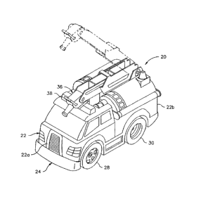
toy vehicle
further includes a base or launching pad where the spring and the hammer are
mounted within
the base. The toy vehicle is pushed into the base so as to rest against the
hammer with the
spring in the compressed position. A release mechanism on the base allows the
spring and
hammer to extend rapidly pushing the toy vehicle and propelling the toy
vehicle forward.
[0005] In yet another, even more complex version of a spring actuated toy
vehicle, the toy
vehicle has a spring mounted internally to the vehicle coupled to a hammer and
is used in
combination with a base having a launching lever to release the toy vehicle
and subsequently
the hammer and spring to thereby propel the toy vehicle forward.
[0006] Other toy vehicles that are not spring actuated are propelled by
conventional
electrical motors include figurines that are moved by a system of levers,
gears and cams to
simulate action by the figurines. The gears are in mesh with take-off gears
from the drive
motor to provide the power for movement.
[0007] What is not provided by the previously disclosed spring actuated toy
vehicles and
toy vehicles with moving figurines is a toy vehicle that moves or actuates a
moveable part of
the vehicle in addition to propelling the vehicle from a common spring biased
mechanism.
BRIEF SUMMARY OF THE INVENTION
[0008] Briefly stated, in one aspect of the present invention is a key
activated toy vehicle.
The toy vehicle comprises a body having a front end, a rear end and an
exterior. The toy
179725 v1
CA 02389263 2002-06-06
vehicle also comprises a chassis that accommodates the body and has at least a
front wheel
proximate the front end and a rear wheel proximate the rear end. At least one
of the body and
the chassis defines an opening to an interior of the toy vehicle. The toy
vehicle also includes a
spring supported within the vehicle so as to be compressed by a key inserted
through the
opening and to propel the toy vehicle away from the key upon decompressing.
The toy vehicle
also includes a moveable part having at least a portion on the exterior of the
body and being
supported on at least one of the chassis and the body for movement between a
first position and
a second position. The toy vehicle further includes an actuator mechanism
operably coupled
with the spring and moveably mounted within the vehicle so as to be coupled
with the
moveable part so as to move the part from the first position to the second
position as the
actuator mechanism moves against the bias of the spring.
BRIEF DESCRIPTION OF THE SEVERAL VIEWS OF THE DRAWINGS
[0009] The foregoing summary, as well as the following detailed description of
preferred
embodiments of the invention, will be better understood when read in
conjunction with the
appended drawings. For the purpose of illustrating the invention, there are
shown in the
drawings embodiments which are presently preferred. It should be understood,
however, that
the invention is not limited to the precise arrangements and instrumentalities
shown.
[0010] In the drawings:
[0011] Fig. 1 is a perspective view of a key activated toy vehicle in
accordance with a first
preferred embodiment of the present invention;
[0012] Fig. 2 is an exploded view of the toy vehicle of Fig. l;
[0013] Fig. 3 is a perspective view of a key activated toy vehicle in
accordance with a
second preferred embodiment of the present invention;
[0014] Fig. 4 is an exploded view of the toy vehicle of Fig. 3
[0015] Fig. 5 is a perspective view of a key activated toy vehicle in
accordance with a third
preferred embodiment of the present invention;
[0016] Fig. 6 is an exploded view of the toy vehicle of Fig. 5
. [0017] Fig. 7a is a perspective view of a key activated toy vehicle in
accordance with a
fourth preferred embodiment of the present invention with a moveable part in a
first position;
[0018] Fig. 7b is a perspective view of the key activated toy veshicle of Fig.
7A with the
moveable part in a second position; and
[0019] Fig. 8 is an exploded view of the toy vehicle of Fig. 7.
2
t~9~2s ~t
CA 02389263 2002-06-06
DETAILED DESCRIPTION OF THE INVENTION
(0020] Certain terminology is used in the following description for
convenience only and is
not limiting. The words "right," "left," "lower" and "upper" designate
directions in the
drawings to which reference is made. The words "inwardly" and "outwardly"
refer to
S directions toward and away from respectively, the geometric center of the
device discussed and
designated parts thereof. The terminology includes the words above
specifically mentioned,
derivatives thereof and words of similar import. Additionally, the word "a" as
used in the
claims and in the corresponding portions of the specification, means "one or
more than one."
[0021] In the drawings, like numerals are used to indicate like elements
throughout.
Referring to the drawings in detail, there is shown in Figs. 1-2 a key
activated toy vehicle 20 in
accordance with a first preferred embodiment of the present invention.
Preferably, the key
activated toy vehicle 20 has the overall appearance of either a fire rig, a
fire truck, an
ambulance, a rescue vehicle, a K-9 wagon, a police car, an emergency vehicle,
a tow truck, a
sport utility vehicle, an off raad vehicle, a boat, a hovercraft, a search
light vehicle, or the like.
1 S But, the key activated toy vehicle 20 may have other overall appearances
without departing
from the present invention. As shown in pigs. 1-2, the presently preferred
embodiment has the
overall appearance of a fire truck with a moveable part in the form of a
ladder.
[0022] The key activated toy vehicle 20 that is propelled utilizing a key
includes a body 22 ,
a chassis 24 and a plunger 26 supported in one of the chassis 24 and the body
22. The body 22
has a front end 22a and a rear end 22b. The chassis 24 accommodates the body
22 and has at
least a front wheel 28 proximate the front end 22a of the body 22 and a rear
wheel 30 proximate
the rear end 22b of the body 22. Preferably, the key activated toy vehicle 20
has two front
wheels 28 and two rear wheels 30 moveably mounted on axles 29 and 31,
respectively. At least
one of the body 22 and the chassis 24 defines an opening 23 to an interior of
the key activated
2S toy vehicle 20. Preferably, the body 22 defines the opening 23. A spring 32
is supported
within the key activated toy vehicle 2U so as to be compressed by a key SO
inserted through the
opening 23 and to propel the toy vehicle 20 away from the key upon
decompressing.
Preferably, the spring 32 is operably coupled with the plunger 26 and biases
the plunger 26
toward the rear end 22b of the body 22. The key activated toy vehicle also
includes a moveable
part 36 in the form of a ladder having at least a portion 36a interior to the
body 22 and a portion
(the remainder) exterior to the body 22. The moveable pari 36 is supported on
at least one of
the chassis 24 and the body 22, in this case the body 22, for movement between
a first position
3
179725 v1
CA 02389263 2002-06-06
and a second position. Alternatively, the moveable part 36 may be a door, a
window, a tow
boom, a boom light, a propeller, a vehicle cab, a trunk lid, a water cannon,
fans and the like
without departing from the invention. The key activated toy vehicle 20 further
includes an
actuator mechanism 60 operably coupled with the spring 32 and moveably mounted
within the
toy vehicle 20 so as to be coupled with the moveable part 36 to move the part
36 from the first
position to the second position as the actuator mechanism 60 moves against the
bias of the
spring 32.
[0023] Referring to Fig. 2 in detail, the actuator mechanism 60 includes a key
receiver 34
that is moveably mounted to one of the body 22 and the chassis 24. Preferably,
the key receiver
34 is mounted in the body 22 at the rear end 22b of the body 22 and extends at
least partially
through the opening 23. The key receiver 34 defines at least part o~f a key
slot 35 and is biased
rearwardly by the spring 32. The key receiver 34 rides on a base support 61
with an elongate
channel guide 62 formed in the base support 61. The mechanism 60 also includes
a pivot pin
64, an upwardly extending arm 66, and a torsion spring 68. The elongate
channel guide 62
extends from an end 34a of the key receiver 34 and defines at least part of
the key slot 35. The
pivot pin 64 is moveably mounted within the actuator mechanism 60. The
upwardly extending
arm 66 has an upper, contact end 66a, a lower, pivot end 66b, a spring slot
66c and a pin hole
66d to receive the pivot pin 64 at the pivot end 66b. The torsion spring 68
has a first end 68a in
the spring slot 66c of the arm 66 and a second end 68b resting on an upper
surface of the key
receiver 34. The torsion spring 68 biases the arm 66 toward an upright
position. When the key
receiver 34 is pushed into an interior chamber of the key activated toy
vehicle 20 by the force
of a user, the contact end 66a of the upwardly extending arm 66 contacts the
interior portion
36a of the moveable part 36 thereby causing the moveable part 36 to move from
the first
position (solid lines in Fig. 1 ) to the second position (phantom lines in
Fig. 1 ).
[0024] The key activated toy vehicle 20 also includes a circuit 40 having a
battery or
batteries BT1, BT2, BT3 mounted within at least one of the body 22 and the
chassis 24 and
held in place by a battery compartment cover 21. Preferably, the batteries
BTI, BT2, BT3 are
mounted in the chassis 24. A light 42 is connected to the circuit 40 so as to
be selectively
illuminated. Preferably, the light 42 is mounted through a hole 19 in the top
o.f the body 22
under a light bar or lens cap 38. Additionally, the key activated toy vehicle
20 includes a sound
generator 44 electrically connected to the circuit 40 for generating sound
such as sirens, horns,
and the like. Preferably, the sound generator 44 is a conventional speaker.
However, the sound
4
179725 v1
CA 02389263 2002-06-06
generator 44 may be other known sound generating devices such Piezoelectric
ceramic disks,
electromechanical reeds and the like, without departing from the broad scope
of the present
invention. T'he circuit 40 further includes a contact switch 46 which is a
normally-open, single-
pole, dry-contact-type switch having a cam 46a on one of the contacts such
that upon contact
with either the plunger 26 or the key receiver 34, the switch is closed
causing the circuit 40 to
energize the light 42 and the sound generator 44. The switch 46 may be other
known types of
switches without departing from the broad inventive concept herein.
[0025] Preferably, the key activated toy vehicle 20 is used in combination
with the key 50.
The key 50 includes an elongate key member 52 having a first end 52a
configured for receipt
I 0 into the key receiver 34, a clasp member ~4 moveably attached to the
elongate key member to
pivot on pin 57 between a locked position and a released position, and a
spring 56 positioned to
bias the clasp member 54 into the locked position. Preferably, the clasp
member 54 includes a
detent SS suitable for engagement in a retaining slot 25 in the chassis 24 of
the key activated
toy vehicle 20. Preferably, the spring 56 is a torsion-type spring having
first and second torsion
arms 56a, 56b. The key 50 further includes a thumb switch or thumb rest 58
which is fixedly
attached to an opposing end 54b of clasp member 54 that extends through a ring
at a second end
52b of the key member 52.
[0026] The first end 52a of the elongate key member 52 is designed (sized and
shaped) to
be inserted into the key slot 35 and may have integrally molded markings
similar to a key. The
thumb rest 58 has the overall appearance of a badge, in the presently
preferred embodiment the
thumb rest 58 has the overall appearance of a fireman's badge. The thumb rest
58 may have the
overall appearance of other badges and other devices without departing from
the present
invention. Preferably the elongate key member 52, the clasp member 54, and the
thumb rest 58
are formed of a molded polymeric material. However, the elongate member 52,
the clasp
member 54, and the thumb rest 58 may be formed of other materials such as
wood, metal and
the like and by other processes such as machining, carving and the like
without departing from
the present invention.
[0027] In use, a user can press an exterior portion of the key receiver 34
into the key
activated toy vehicle 20 causing the upwardly extending arm 66 to contact an
interior portion of
the moveable part 36 moving the moveable part 36 from the first position to
the second position
and also making contact with the earn 46a on the switch 46 closing the switch
46 and causing
the light 42 to illuminate the light bar 38 and the sound generator 44 to
generate a noise such as
5
179725 v1
CA 02389263 2002-06-06
a siren or a horn. When the user removes pressure from the key receiver 34,
the spring 32
biases the key receiver 34 toward the rear end 22b of the body 22 allowing the
moveable part
36 to return from the second position to the first position and the circuit 40
turns off the light 42
and the sound generator 44 after a predetermined period of time. A user may
also insert the
elongate key member 52 of the key 50 into the key slot 35 against the biasing
force of the
spring 32 pushing the key receiver 34 and the plunger 26 inwardly.. If the
user releases pressure
from the thumb rest 58, the detent 55 of the clasp member 54 engages the
retaining slot 25 of
the chassis 24. The key 50 is thereby retained in a locked position with the
spring 32 fully
compressed (loaded) ready to release pressure on the plunger 26 and the key
receiver 34. The
moveable part 36 is in the second position or in this case the ladder is
extended vertically at an
angle from the top of the body 22. When the user grasps a second end 52b of
the elongate key
member 52 and gently presses on the thumb rest 58, the clasp member 54 moves
from the
locked position to the released position against the biasing force of torsion
spring 56. The
detent 55 of the clasp member 54 moves out of the retaining slot 25 allowing
the spring 32 to
fully extend biasing the plunger 26 rapidly towards the rear of the vehicle
imparting a
propulsion force on the key activated toy vehicle 20 and allowing the key
activated toy vehicle
to move in the forward direction. In the presently preferred embodiment, the
spring 32
serves a dual role in biasing the key receiver 34 and the plunger 26 toward
the rear end 22b of
the body 22 and also as propulsion mechanism. It is contemplated that other
more complicated
20 propulsion mechanisms could be used in combination with the devices
disclosed herein without
departing from the present invention.
[0028] Figs. 3-4 show a key activated toy vehicle 120 in accordance with a
second
preferred embodiment of the present invention. 'fhe key activated toy vehicle
120 has the
overall appearance of a K-9 wagon with a side door that opens to reveal K-
9/dog figurines
therein. The key activated toy vehicle 120 includes a body 122 , a chassis 124
and a plunger
126 supported in one of the chassis 122 and the body 124. The body 122 has a
front end 122a
and a rear end 122b. The chassis 124 accommodates the; body 122 and has at
least a front
wheel 128 proximate the front end 122a of the body 122 and a rear wheel 130
proximate the
rear end 22b of the body 122. Preferably, the key activated toy vehicle 120
has two front
wheels 128 and two rear wheels 130 moveably mounted on axles 129 and 131,
respectively. At
least one of the body 122 and the chassis 124 defines an opening 123 to an
interior of the key
activated toy vehicle 120. Preferably, the body 122 defines the opening 123. A
spring 132 is
6
179725 v1
CA 02389263 2002-06-06
supported within the key activated toy vehicle 120 so as to be compressed by a
key 150 inserted
through the opening 123 and to propel the toy vehicle l 20 away from the key
150 upon
decompressing. Preferably, the spring 132 is operably coupled with the plunger
126 and biases
the plunger 126 toward the rear end 122b of the body 122. The key activated
toy vehicle 120
also includes a moveable part 136 in the form of an opening side-door having a
portion exterior
to the body 122 and a portion interior to the body 122 and is supported on at
least one of the
chassis 124 and the body 122 for movement between a first position and a
second position. The
key activated toy vehicle 120 further includes an actuator mechanism 160
operably coupled
with the spring 132 and moveably mounted within the vehicle so as to be
coupled with the
moveable part 136 to move the part 136 from the first position to the second
position as the
actuator mechanism 160 moves against the bias of the spring 132.
[0029] Referring to Fig. 4 in detail, the actuator mechanism 160 includes a
key receiver 134
that is moveably mounted generally at one of either the front end 122a or the
rear end 122b of
the body 122. Preferably the key receiver 134 is mounted at the rear end 122b
of the body 122
and extends at least partially through the opening 123. The key receiver 134
defines at least
part of a key slot 135 and is biased rearwardly by the spring 132. The key
receiver 134 rides on
a base support 161 with an elongate channel guide 162 fornied in the base
support 161. The
mechanism 160 also includes a pivot pin 164, an arm 166, a rotary cam 167 and
first and
second torsion springs 168, 169. The elongate channel guide 162 extends from
an end 134a of
the key receiver 134 and defines at least part of the key slot 135. The pivot
pin 164 is
moveably mounted within the actuator mechanism 160. The arm 166 has a contact
end 166a, a
pivot end 166b, a spring slot 166c and a pin hole 166d to receive the pivot
pin 164 at the pivot
end 166b. The first torsion spring 168 has a first end 7 68a in the spring
slot 166c of the arm
166 and a second end 168b resting on an interior channel of the moveable part
136. The second
torsion spring 169 has a first end 169a resting on an interior surface of the
body 122 and a
second end 169b resting on another interior channel of the moveable part 136.
The first and
second torsion springs 168, 169 bias the arm 166 and the moveable part 136
toward the first
position where the door appears closed (solid lines in Fig. 3). When the key
receiver 134 is
pushed into an interior chamber of the key activated toy vehicle 120 by the
force of a user, the
rotary cam 167 moves the arm 166 and the contact end 166a of the arm 166
contacts the interior
portion of the moveable part 136 thereby causing the moveable part 136 to move
from the first
7
179725 vt
CA 02389263 2002-06-06
position (solid lines in Fig. 3) to the second position (phantom lines in Fig.
3) against the bias
of the first and second torsion springs 168, 169.
[0030] The key activated toy vehicle 120 also includes the circuit 40
identical to the circuit
40 described above. The circuit 40 has the battery or batteries BT1, BT2, BT3
mounted within
at least one of the body 122 and the chassis 124 and held in place by a
battery compartment
cover 121. Preferably, the batteries BT1, BT2, BT3 are mounted in the chassis
124.
Preferably, the light 42 is mounted through a hole I 19 in the top of the body
122 under a light
bar or lens cap 138. The cam 46a on one of the contacts of the switch 46 for
engagement with
either the plunger 126 or the key receiver 134 to close the switch 46 and
causing the circuit 40
to energize the light 42 and the sound generator 44.
[0031] Preferably, the key activated toy vehicle 120 is used in combination
with the key
150. The key 150 includes the elongate key member 52 configured for receipt
into the key
receiver 134, the clasp member 54 moveably attached to the elongate key member
52 to pivot
on pin 57 between a locked position and a released position, and th.e torsion
spring 56
positioned to bias the clasp member into the locked position. Preferably, the
clasp member 54
includes the detent 55 suitable for engagement in a retaining slot 125 in the
chassis 124 of the
key activated toy vehicle 120. The key 150 further includes a thumb switch or
thumb rest 158
fixedly attached to an opposing end 54b of clasp member 54 that extends
through a ring at the
second end 52b of the key member 52.
[0032] In use, a user can press an exterior portion of the key receiver 134
into the key
activated toy vehicle causing the rotary cam 167 to move the arm 166 and the
arm 166 to
contact the interior portion of the moveable part 136 moving the moveable part
136 from the
first position to the second position and also closing or making contact with
the cam 46a of the
switch 46 closing the switch 46 thereby causing the light 42 to illuminate the
light bar 138 and
the sound generator 44 to generate a noise such as a siren or a horn. When the
user removes
pressure from the key receiver 134, the spring 132 biases the key receiver 134
toward the rear
end 122b of the body 122 and allowing the moveable part 136 to return from the
second
position to the first position and the circuit 40 turns off the light 42 and
the sound generator 44
after a predetermined period of time. A user may also insert the elongate key
member 52 of the
key 150 into the key slot 135 against the biasing force of the spring; 132
pushing the key
receiver 134 and the plunger 126 inwardly. If the user releases pressure from
the thumb rest
158, the detent 55 of the clasp member 54 engages the retaining slot 125 of
the chassis 124.
8
179725 v1
CA 02389263 2002-06-06
The key 1 SO is thereby retained in a locked position with the spring 132
fully compressed
(loaded) ready to release pressure on the plunger 126 and the key receiver
134. The moveable
part 136 is in the second position or in this case the door is rotated open
exposing the K-9/dog
figurines from within the interior of the body 122. When the user grasps the
second end 52b of
the elongate key member 52 and gently press on the thumb rest 158, the clasp
member 54
moves from the locked position to the released position against the biasing
force of the torsion
spring 56. The detent 55 of the clasp member 54 moves out of the retaining
slot 125 allowing
the spring 132 to fully extend biasing the plunger 126 rapidly towards the
rear of the key
activated toy vehicle 120 imparting a propulsion force on the key activated
toy vehicle 120 and
allowing the key activated toy vehicle 12U to move in the forward direction.
Similar to the first
preferred embodiment, the spring 132 serves a dual role in biasing the key
receiver 134 and the
plunger 126 toward the rear end 122b of the body 122 and also as a propulsion
mechanism.
[0033] Figs. 5-6 show a key activated toy vehicle 220 in accordance with a
third preferred
embodiment of the present invention. The key activated toy vehicle 220 has the
overall
appearance of a rescue hovercraft with propellers that raise. 'The key
activated toy vehicle 220
includes a body 222 , a chassis 224 and a plunger 226 supported in one of the
chassis 222 and
the body 224. The body 222 has a front end 222a and a rear end 222b. The
chassis 224
accommodates the body 222 and has at least a front wheel 228 proximate the
front end 222a of
the body 222 and a rear wheel 230 proximate the rear end 222b of the body 222.
Preferably,
the key activated toy vehicle 220 has two front wheels 228 and two rear wheels
230 moveably
mounted on axles 229 and 231, respectively. At least one of the body 222 and
the chassis 224
defines an opening 223. Preferably, both the body 222 and the chassis 224
together define the
opening 223. A spring 232 is supported within the key activated toy vehicle
220 so as to be
compressed by a key 250 inserted through the opening 223 and to propel the toy
vehicle 220
away from the key 250 upon decompressing. Preferably, the spring 232 biases
the plunger 226
toward the rear end 222b of the body 222. The key activated toy vehicle also
includes a
moveable part 236 in the form of rotatable, moveable propellers supported on
at least one of the
chassis 224 and the body 222, in this case the body 222, for movement between
a first position
and a second position. The key activated toy vehicle 220 further includes an
actuator
mechanism 260 operably coupled with the spring 232 and moveably mounted within
the
vehicle so as to be coupled with the moveable part 236 to move the. part 236
from the first
9
179725 v1
CA 02389263 2002-06-06
position to the second position as the actuator mechanism 260 moves against
the bias of the
spring 232.
[0034] Referring to Fig. 6 in detail, the actuator mechanism 260 includes a
key receiver 234
that is moveably mounted generally at one of either the front end 222a or the
rear end 222b of
the body 222. Preferably, the key receiver 234 is mounted in the body 222 and
extends at least
partially through the opening 223. 'The key receiver 234 defines at least part
of a key slot 235
and is biased rearwardly by the spring 232. The key receiver 234 rides on a
base support 261
with an elongate channel guide 262. The mechanism 260 also includes a pivot
pin 264, a row
of teeth 266 disposed on a portion of the key receiver 2 34, and a translation
gear 268. The
elongate channel guide 262 extends from an end 234a of the key receiver 234
and defines at
least part of the key slot 235. The pivot pin 264 is moveably mounted
partially within the
moveable part 236, the body 222, the chassis 224 and the base support 262 of
the actuator
mechanism 260. When the key receiver 234 is pushed into an interior chamber of
the key
activated toy vehicle 220 by the force of a user, the row of teeth 266, in
mesh with the
translation gear 268, rotates the translation gear 268 which is coupled to the
pivot pin 264, also
causing the pivot pin 264 to rotate. 'fhe pivot pin 264 is coupled to the
moveable part 236
thereby causing the moveable part 236 to move from the first position (solid
lines in Fig. S) to
the second position (phantom lines in Fig. S). In the presently preferred
embodiment, the
moveable part 236 is mounted entirely on the outside of the body 222 of the
key activated toy
vehicle 220, but appropriate contours and fittings are formed in the body 222
to allow the
moveable part to partially rotate and to be stored in an almost flush storage
position (the first
position).
[0035] The key activated toy vehicle 220 also includes the circuit 40
identical to the circuit
40 described above for the other embodiments. The circuit 40 has the battery
or batteries BT1,
BT2, BT3 mounted within at least one of the body 222 and the chassis 224 and
held in place by
a battery compartment cover 221. Preferably, the batteries BT1, BT2, BT3 are
mounted in the
chassis 224. Preferably, the light 42 is mounted through a hole 219 in the top
of the body 222
under a light bar or lens cap 238. 'Che cam 46a on one of the contacts of the
switch 46 engages
either the plunger 226 or the key receiver 234 to close the switch 4fi and
cause the circuit 40 to
energize the light 42 and the sound generator 44.
[0036] Preferably, the key activated toy vehicle 220 is used in combination
with the key
250. The key 250 includes the elongate key member 52 configured for receipt
into the key
»9~zs ~~
CA 02389263 2002-06-06
receiver 234, the clasp member 54 moveably attached to the elongate key member
52 to pivot
on pin 57 between a locked position and a released position, and th.e torsion
spring 56
positioned to bias the clasp member 54 into the locked position, similar to
the other keys 50,
150 described above. The key 250 further includes a thumb switch or thumb rest
258 which is
fixedly attached to an opposing end 54b of clasp member 54 that e:Ktends
through a ring at a
second end 52b of the key member 52. Preferably, the clasp memt>er 54 includes
the detent 55
suitable for engagement in a retaining slot 225 in the chassis 224 o:f the key
activated toy
vehicle 220. The first end 52a of the elongate key member 252 is designed to
be inserted into
the key slot 235. The thumb rest 258 of the presently preferred embodiment has
the overall
appearance of a patrol or harbor patrol badge. The thumb rest 258 may have the
overall
appearance of other badges and other devices without departing from the
present invention.
[0037] In use, a user can press an exterior portion of the key receiver 234
into the key
activated toy vehicle 220 causing the row of teeth 266 to rotate the
translation gear 268 and the
pivot pin 264 thereby moving the moveable part 236 from the first position to
the second
1 S position and also making contact with the cam 46a of the switch 46 closing
the switch and
causing the light 42 to illuminate the light bar 238 and the sound gf,nerator
44 to generate a
noise such as a siren or a horn. When the user removes pressure from the key
receiver 234, the
spring 232 biases the key receiver toward the rear end 222b of the body 222
and allows the
moveable part 236 to return from the second position to the first position and
the circuit 40
turns off the light 42 and the sound generator 44 after a predeter~rnined
period of time. A user
may also insert the elongate key member 52 of the key 250 into the key slot
235 against the
biasing force of the spring 232 pushing the key receiver 234 and the plunger
226 inwardly. If
the user releases pressure from the thumb rest 258, the detent 55 of the clasp
member 54
engages the retaining slot 225 of the chassis 224. The key 250 is thereby
retained in a locked
position with the spring 232 fully compressed (loaded) ready to release
pressure on the plunger
226 and the key receiver 234. The moveable part 236 is in the second position
or in this case
the propellers are vertically extended from the top of the body 222 at some
predetermined
angle. When the user grasps the second end 52b of the elongate key member 52
and gently
presses on the thumb rest 258, the clasp member 54 moves from the locked
position to the
released position against the biasing force of the torsion spring 56. The
detent 55 of the clasp
member 54 moves out of the retaining slot 225 allowing the spring 232 to fully
extend biasing
the plunger 226 rapidly towards the rear of the key activated toy vehicle 220
imparting a
179725 v1
CA 02389263 2002-06-06
propulsion force on the toy vehicle 220 and allowing the key activated toy
vehicle 220 to move
in the forward direction. In the presently preferred embodiment, the spring
232 serves a dual
role in biasing the key receiver 234 and the plunger 226 toward the rear end
222b of the body
222 and also as a propulsion mechanism.
[0038] Referring to Figs. 7a-7b and 8 there is shown a key activated toy
vehicle 320 in
accordance with a fourth preferred embodiment of the present invention. The
key activated toy
vehicle 320 has the overall appearance of either a police cruiser (Fig. 7a) or
an undercover
police car (Fig. 7b). The key activated toy vehicle 320 has a body 322, a
chassis 324, and a
plunger 326. The body 322 has a front end 322a and a rear end 322b. The
chassis 324
accommodates the body 322 and has at least a front wheel 328 at the front end
322a of the body
322 and rear wheel 330 at the rear end 322b of the body 322. Preferably, the
toy vehicle 320
has two front wheels 328 moveably mounted on a front axle 329 and two rear
wheels 330
moveably mounted on two rear axles 331x, 331b. At least one of the body 322
and the chassis
324 defines an opening 323 to an interior of the key activated toy vehicle
320. Preferably, the
chassis 324 defines the opening 323. At least a ftrst spring 332 is supported
within the key
activated toy vehicle 320 so as to be compressed by a key 350 inserted through
the opening 323
and to propel the toy vehicle 320 away from the key upon decompressing.
Preferably, the key
activated vehicle includes three springs 332, 348, 349. Preferably, one or
more of the springs
332, 348, 349 are operably coupled with the plunger 326 and bias the plunger
326 toward the
rear end 322b of the body 322. The key activated toy vehicle 320 also includes
a moveable part
336 in the form of rotatable cab portion supported on at least one of the
chassis 324 and the
body 322 for movement between a first position and a second position. In the
presently
preferred embodiment, the moveable part 336 is mounted to the body 322 to
pivot about a
horizontal axis H (dashed line in Fig. 8). Preferably, the moveable part 336
has a first surface
337 and a second surface 339 each having sufficiently different features, to
differentiate the
first and second surfaces. The key activated toy vehicle 320 further includes
an actuator
mechanism 360 operably coupled with the first spring 332 and moveably mounted
within the
vehicle so as to be coupled with the moveable part 336 to move the part 336
from the first
position to the second position as the actuator mechanism 360 moves against
the bias of the
first spring 332.
[0039] Referring to Fig. 8 in detail, the actuator mechanism 360 includes a
crown gear 327
connected to the moveable part 336 proximate a location along the horizontal
axis H. The
12
179725 v1
CA 02389263 2002-06-06
crown gear 327 is fixed to the moveable part 336 by known means and preferably
has gear teeth
327a on an end extending away from the moveable part 336. A drive gear 323 is
in
engagement with the crown gear 327. The actuator mechanism 360 also includes a
lever 333
moveably coupled with the drive gear 323, the first spring 332 is positioned
to bias the lever
333 toward the rear end 322b of the body 322. Preferably, an end :333A of the
lever 333
extends out of a second opening 323 defined by the chassis 324 to .allow the
lever 333 to be
pushed from outside the toy vehicle 320.
[0040] The moveable part 336 is also moved from the first position displaying
the first
surface 337 to the second position displaying the second surface 339 against
the biasing force
of the springs 332, 348, 349 in response to movement of the plunger 326.
Preferably, the
plunger 326 is also accessible through the opening 323 to allow movement by
the key 350
when the key 350 is inserted into the opening 323. Due to the length of the
lever 333 and the
weight of the moveable part 336, the second and third biasing springs 348, 349
are provided in
addition to the first spring 332 to return the key receiver 334 and the lever
333 to a position
toward the rear end 322b of the body 322 with sufficient force to propel the
key activated toy
vehicle 320 and to turn the moveable part 336 back from the second position to
the first
position. Obviously any number of springs could be utilized without departing
from the broad
inventive scope of the present invention.
[0041] The key activated toy vehicle 320 also includes the circuit 40
identical to the circuit
40 described above for the other embodiments; however, the circuit 40 is
preferably mounted
within the moveable part 336 in the presently preferred embodiment. The
circuit 40 has the
battery or batteries BT1, BT2, BT:3 mounted within at least one of the
moveable part 336, the
body 322 and the chassis 324 and held in place by a battery compartment cover
321.
Preferably, the batteries BT1, BT2, BT3 are mounted in the moveable part 336.
Preferably, the
light 42 is mounted through a hole 319 in the first surface 337 of the
moveable part 336 under a
light bar or lens cap 338. The cam 46a on one of the contacts of the switch 46
engages a
protrusion on the crown gear 327 to close the switch 46 and cause the circuit
40 to energize the
light 42 and the sound generator 44.
[0042] Preferably, the key activated toy vehicle 320 is used in combination
with the key
350. The key 350 includes the elongate key member 52 configured for receipt
into the key
receiver 334, the clasp member 54 moveably attached to the elongate key member
52 to pivot
between a locked position and a released position, and the torsion spring 56
positioned to bias
1 3
179725 v1
CA 02389263 2002-06-06
the clasp member 54 into the locked position, similar to the other keys 50,
150, 250 described
above. The clasp member 52 is pivotally attached to the elongate hey member by
the pivot pin
57. The key 350 further includes a thumb switch or thumb rest 358 pivotally
attached to the
elongate key member 52 by another pivot pin 57a and is biased by a second
torsion spring 56a.
Preferably, the clasp member 54 includes the detent 55 suitable for engagement
in a retaining
slot 325 in the chassis 324 of the key activated toy vehicle 320. The first
end 52a of the
elongate key member 52 is designed to be inserted into the key slot 335. The
thumb rest 358 of
the presently preferred embodiment has the overall appearance of a policeman's
badge. The
thumb rest 358 may have the overall appearance of other badges and other
devices without
departing from the present invention.
[0043] In use, a user can press an exterior portion 333A of the lever 333 into
the key
activated toy vehicle 320 causing the lever 333 to turn the drive gear 323
thereby rotating the
crown gear 327. The moveable part 336 is moved from the first position
displaying the first
surface 33? to the second position displaying the second surface 339 against
the biasing force
of the first spring 332. The crown gear 327 also makes contact with the cam
46a of the switch
46 closing the switch 46 and causing the light 42 to illuminate the light bar
338 and the sound
generator 44 to generate a noise such as a siren or a horn. When the user
removes pressure
from the exterior portion 333A of the lever 333, the first spring 332 biases
the lever 333 toward
the rear end 322b of the body 322 and allows the moveable part 336 to return
from the second
position displaying the second surface 339 to the first position displaying
the first surface 337
and the circuit 40 turns off the light 42 and the sound generator 44 after a
predetermined period
of time. A user rnay also insert the elongate key member 52 of the key 350
into the key slot
335 against the biasing force of the first, second and third springs 332, 348,
349 pushing the
key receiver 334, the plunger 326, and the lever 333 inwardly. if the user
releases pressure
from the thumb rest 358, the detent 55 of the clasp member 54 engages the
retaining slot 325 of
the chassis 324. The key 350 is thereby retained in a locked position with the
first, second and
third springs 332, 348, 349 fully compressed (loaded) ready to release
pressure on the plunger
326, the lever 333 and the key receiver 334. The moveable part 336 is in the
second position or
in this case the second surface 339 is displayed from the top of the body 322.
When the user
grasps the second end 52b of the elongate key member 52 and gently presses on
the thumb rest
358, the clasp member 54 moves fiom the locked position to the released
position against the
biasing force of torsion spring 56. The detent 55 of the clasp member 54 moves
out of the
14
f ~9~zs ~t
CA 02389263 2002-06-06
retaining slot 325 allowing the first, second and third springs 332, 348, 349
to fully extend
biasing the plunger 326 rapidly towards the rear of the key activated toy
vehicle 320 imparting
a propulsion force on the key activated toy vehicle 32() and allowing the key
activated toy
vehicle 320 to move in the forward direction. In the presently preferred
embodiment, the first,
second and third springs 332, 348. 349 serve a dual role in biasing the key
receiver 334, the
lever 333 and the plunger 226 toward the rear end 322b of the body 322 and
also as a
propulsion mechanism.
[0044] From the foregoing, it can be seen that the present invention comprises
a key
activated toy vehicle including a vehicle or moveable part in or on either the
chassis or the body
wherein the vehicle or moveable part is moved by mechanical power from a key
receiver, a
lever or plunger that is spring biased to also propels the key activated toy
vehicle. It will be
appreciated by those skilled in the art that changes could be made to the
embodiments described
above without departing from the broad inventive concept thereof. It is
understood, therefore,
that this invention is not limited to the particular embodiments disclosed,
but it is intended to
cover modifications within the spirit and scope of the present invention as
defined by the
appended claims.
o9~zs ~a