Note: Descriptions are shown in the official language in which they were submitted.
t '~~ i~ ~ ~~ ~
CA 02389513 2002-06-06
r
PATENT
Wayne A. Guyer
DRIVE SYSTEM FOR COMBINE REEL BATS
Bac round of the Invention
The present invention relates to a new and improved drive for the bat
reel assemblies of combines used to harvest crops such as canola, rye, oats,
wheat, soybeans and other crops, and more particularly, to a new and
improved drive system for combine reel bats which allows the bats to feed the
crop into the combine continuously at a more consistent rate than heretofore
in
cooperation with the cutter to reduce the breakage of reel bat fingers and
combine down time, increase the efficiency of the combine, and decrease crop
loss.
Combines are commonly used by farmers all over the world to harvest
their crops. Various varieties of grains, kernels and beans that range in
height
from a couple inches to several feet above ground, are cut by the header and
fed into the combine. Combines which are designed to harvest these crops
have a floating header pivotally connected to the combine in front of a feed
auger. Mounted over the header are a plurality of elongated bats arranged in
circumferentially spaced apart and parallel fashion to define a reel which
rotates as the combine moves down the field. Each of the bats of the reel
assembly have a plurality of spaced apart fingers or an elongated paddle
("fingers" herein) which rake through the crop and presents the crop to the
cutter on the leading edge of the header and feeds the cut crop into the auger
1
ii
. .. a ~'~~xI4' S!
CA 02389513 2002-06-06
1
of the combine. Depending upon the crop size, the moisture of the crop and
the cutting conditions, feeding the crop into the auger may present problems.
While it is desired to have a constant flow of cut crop fed over the header
bottom and into the auger, typically, bunches of cut crop collect on the
header
bottom and are fed into the auger in clumps causing a number of problems
ranging from higher fuel consumption, inconsistent operation to breakage and
shut down. It is therefore highly desirable to provide a new and improved
drive system for the bat reel assembly of a combine header. It is also highly
desirable to provide a new and improved drive system for the bat reel
assembly of a combine header by which crops are properly presented for
cutting and cut crops are more continuously and evenly fed into the auger.
All such combines either have a floating header or a rigid or fixed
header. Both headers have at its leading edge a cutter blade. The floating
header pivotally hangs from the header such that the header gravitationally
lays on the ground and follows the contour of the ground. Because of the
unevenness of the ground, the header may move up and down causing a
number of problems ranging from feed inconsistencies to actual impingement
upon the fingers of the rotating bats resulting in finger breakage and down
time. It is therefore highly desirable to provide a new and improved drive
system for the bat reel assembly of a combine header to cooperate with a
floating header and reduce finger breakage. It is also highly desirable to
provide a new and improved drive system for the bat reel assembly of a
combine header to provide for improved feeding of cut crop into the auger
2
1.1 1. : q. I I
CA 02389513 2002-06-06
.3
with both floating headers and fixed headers and at the same time to reduce
bat finger breakage and combine down time. It is also highly desirable to
provide a new and improved drive system for the bat reel assembly of a
combine header which allows the bats to accommodate a floating header in all
header positions.
Farmers presently adjust the height of the bats from the header in its
highest posirion such that the rake fingers of a bat will clear the header in
all
header positions. This means that when the header is in is lowest position,
the
rake fingers of the bat may be positioned away from the header 9 to 15 inches
or so. Thus, the rake fingers do not adequately feed cut crop into the auger
of
the combine and cut crop is left on the field. Additionally, cut crop is
bunched
up on the header and fed into the auger in clumps discontinuously. In order to
accomplish continuous, consistent and even feeding of crop into the auger, the
rake fingers of the bats desirably are positioned away from the header
approximately '/2 to 4 inches. However, if the bats were adjusted so that the
fingers of the bats were approximately ~/a to 4 inches from the floating
header,
the header in normal operation would repeatedly engage the reel fingers and
the reel fingers would be broken causing combine down time. It is therefore
highly desirable to provide a new and improved drive system for the bat reel
assembly of a combine header by which the reel forgers cooperate with the
floating header to continuously feed cut crop into the auger at a more
consistent rate. It is also highly desirable to provide a new and improved
drive
system for the bat reel assembly of a combine header which rotates the reel
3
;.;. _:I I
CA 02389513 2002-06-06
3
fingers as they approach the header to provide the desired feed of cut crop
into
the auger continuously and at a more consistent rate without finger breakage.
The shape of the headers in relation to the reel fingers of the bats also
provides that typically the distance between the reel fingers of the bats and
the
header increase as the crop approaches the auger. In some instances, typically
the distance between the reel fingers and the bat may increase from
approximately 6 to 7 inches to approximately 12 to 15 inches away from the
header as the crop is fed into the auger. Such does not provide for an even
and
consistent flow of cut crop into the auger. It is therefore highly desirable
to
provide a new and improved drive system for the bat reel assembly of a
combine header whereby the reel fingers of the bats are spaced apart from the
header essentially the same distance over the entire distance between the
cutter
bar to the auger. It is also highly desirable to provide a new and improved
drive system for the reel fingers of each bat whereby the reel fingers begin
to
rotate ahead of the header into a collapsed condition and to rotate in the
opposite direction to extend the fingers into their normal generally vertical
position adjacent to the auger.
It is therefore highly desirable to provide a new and improved drive
system for the bat assembly of a combine header to lift down crop clear of the
ground by the reel fingers of the bat reel assembly and present the same to
the
cutter bar to efficiently feed the cut crop into the auger continuously and at
a
more consistent rate without finger breakage.
4
i
CA 02389513 2002-06-06
It is also highly desirable to provide a new and improved drive system
for the bat reel assembly of a combine header which presents the cut crop
lengthwise to the combine feed unit and holds the cut crop generally
vertically
in front of the feed auger and presents the cut crop lengthwise to the
thrashing
cylinder thereby to continuously feed the cut crop at a more consistent rate
without finger breakage.
It is also highly desirable to provide a new and improved drive system
for the bat reel assembly of a combine header which allows the combine to top
wheat, oats and other such crops to have more high quality straw available,
reduce combine load and reduce rotor loss.
It is also highly desirable to provide a new and improved drive system
for the reel fingers of each bat which allows the reel fingers to move upon
impact and biases the reel fingers into their generally vertical position
adjacent
to the auger and remote from the header and in their collapsed condition over
the header.
Farmers utilizing combine headers which have a bat reel which rotates
over a header such as above described, often experience cut crop winding
about the bats. This crop entanglement reduces the efficiency of the bats to
feed cut crop into the auger. It is also highly desirable to provide a new and
improved drive system for the bat assembly of a combine at a position remote
from the header to unwind cut crop from the reel fingers. It is therefore
highly
desirable to provide a new and improved drive system for the bat reel
assembly of a combine header which rotates the reel fingers at a position
.;.i: , .~
CA 02389513 2002-06-06
b
remote from the header in the opposite direction to unwind cut crop from the
rake fingers.
It is also highly desirable to provide a new and improved drive system
for the bat reel assembly of a combine header which will cooperate with the
combine header not only to reduce finger breakage, but to more continuously
and evenly feed cut crop into the auger and generally reduce operating costs
up to about twenty percent.
Finally, it is highly desirable to provide a new and improved drive
system for the bat reel assembly of a combine which has all of the above
features.
Summary of the Invention
It is therefore an object of the invention to provide a new and improved
drive system for the bat reel assembly of a combine header.
It is also an object of the invention to provide a new and improved
drive system for the bat reel assembly of a combine header by which crops are
properly presented for cutting and cut crops are more continuously and evenly
fed into the auger.
It is also an object of the invention to provide a new and improved
drive system for the bat reel assembly of a combine header to cooperate with a
floating header and reduce bat finger breakage.
It is also an object of the invention to provide a new and improved
drive system for the bat reel assembly of a combine header to provide for
6
,~.: ~ ~li I
CA 02389513 2002-06-06
3
improved feeding of cut crop into the auger and at the same time to reduce bat
finger breakage and combine down time.
It is also an object of the invention to provide a new and improved
drive system for the bat reel assembly of a combine header which allows the
bats to accommodate a floating header in all header positions.
It is also an object of the invention to provide a new and improved
drive system for the bat reel assembly of a combine header by which the reel
fingers cooperate with the floating header to continuously feed cut crop into
the auger at a more consistent rate.
It is also an object of the invention to provide a new and improved
drive system for the bat reel assembly of a combine header which rotates the
reel fingers as they approach the header to provide the desired feed of cut
crop
into the auger continuously and at a more consistent rate without finger
breakage.
It is also an object of the invention to provide a new and improved
drive system for the bat reel assembly of a combine header whereby the reel
fingers of the bats are spaced apart from the header essentially the same
distance over the entire distance between the cutter bar and the auger.
It is also an object of the invention to provide a new and improved
drive system for the reel fingers of each bat whereby the reel fingers begin
to
rotate ahead of the header into a collapsed condition and to rotate in the
opposite direction to extend the fingers into their normal generally vertical
position adjacent to the auger.
7
~, i ,... . i
CA 02389513 2002-06-06
It is also an object of the invention to provide a new and improved
drive system for the bat reel assembly of a combine header at a position
remote from the header in the opposite direction to unwind cut crop from the
rake fingers.
It is also an object of the invention to provide a new and improved
drive system for the bat assembly of a combine header to lift down crop clear
of the ground by the reel fingers of the bat reel assembly and present the
same
to the cutter bar to efficiently feed the cut crop into the auger continuously
and
at a more consistent rate without forger breakage.
It is also an object of the invention to provide a new and improved
drive system for the bat reel assembly of a combine header which presents the
cut crop lengthwise to the combine feed unit and holds the cut crop generally
vertically in front of the feed auger and presents the cut crop lengthwise to
the
thrashing cylinder thereby to continuously feed the cut crop at a more
consistent rate without finger breakage.
It is also an object of the invention to provide a new and improved
drive system for the bat reel assembly of a combine header which allows the
combine to top wheat, oats and other such crops to have more high quality
straw available, reduce combine load and reduce rotor loss.
It is also an object of the invention to provide a new and improved
drive system for the reel fingers of each bat which allows the reel fingers to
move upon impact and biases the reel fingers into their generally vertical
8
~~~ .ii
CA 02389513 2002-06-06
s
position adjacent to the auger and remote from the header and in their
collapsed condition over the header.
It is also an object of the invention to provide a new and improved
drive system for the bat reel assembly of a combine header which will
cooperate with the combine header not only to reduce finger breakage, but to
more continuously and evenly feed cut crop into the auger and generally
reduce operating costs up to about twenty percent.
It is finally an object of the invention to provide a new and improved
drive system for the bat assembly of a combine which has all of the above
features.
In the broader aspects of the invention there is provided a new and
improved drive system for the bat assembly of a combine by which the reel
fingers of the bat are rotated from their generally vertical position into a
collapsed position and then back into their generally vertical position as the
bat fingers traverse from just prior to the header to just prior to the feed
auger
whereby the reel fingers of the bat can be adjusted to be spaced from the
header in all of its positions to accomplish continuous feed of cut crop into
the
auger at a more constant rate and yet avoid breakage of reel fingers by the
floating header impinging upon the reel fingers during use.
Brief Description of the Drawings
The above-mentioned and other features and objects of the invention
and the manner of attaining them will become more apparent and the invention
9
a =i ~ 'i~~r~i..r ~i
CA 02389513 2002-06-06
itself will be better understood by reference to the following description of
an
embodiment of the invention take in conjunction with the accompanying
drawings wherein:
Figure 1 is a perspective view of a conventional combine showing the
cutter bar, the floating header, the feed auger and rotating bat reel
assembly;
Figure 2 is a perspective end view of the combine illustrated in Fig. 1
with the rotating bat reel assembly in its elevated position with the cab,
engine, grain bin, chain cover and dividers removed for better viewing;
Figure 3 is a fragmentary close-up view showing a conventional bat
reel assembly of the combine in its lowest position;
Figure 4 is a fragmentary close-up view like Fig. 3 showing the bat reel
assembly of the invention in its lowest position;
Figure Sa is a fragmentary, diagrammatic side view showing the
positions of the bat reel assembly and the bats as they rotate above the
header
and in front of the auger in a conventional combine and the finger extension
in
dashed lines;
Figure Sb is an illustration like Figure Sa showing the bat rotation of
the new and improved drive system of the invention as the bats approach the
header and pass by the auger of the combine and the finger extension in
dashed lines;
Figure Sc is an illustration like Sa showing not only the bat rotation of
the new and improved drive system of the invenrion as shown in Fig. 5b, but
also the reverse rotation of the bat fingers remote from the header to unwind
10
ii
CA 02389513 2002-06-06
the stalks of any cut crop which may have wound around the bats in operation
of the combine;
Figure 6 is a plan view of the new and improved bat drive system of
the invention showing the inner mechanism of two of the bat drives in dashed
lines, one of the bat drives being in its extended position and the other of
the
bat drives being in its retracted position;
Figure 7 is a plan view of the new and improved bat reel drive system
of the invention shown in Fig. 6 from the opposite direction thereof showing
one of the bat drives in its extended position;
Figure 8 is a plan view of the new and improved bat reel drive system
of the invention shown in Fig. 6 from the opposite direction thereof with the
cover removed showing one of the bat drives in its extended position and the
interior mechanism in dashed lines;
Figure 9 is a plan view of the new and improved bat reel drive of the
invention showing the inward mechanism in dashed lines;
Figure 10 is a plan view of the new and improved bat reel drive of the
invention taken from a diametrically opposed direction of that of Fig. 9
showing the inward mechanism in dashed lines;
Figure 11 is a plan view of the new and improved bat reel drive of the
invention shown in Figs. 9 and 10 with the cover removed showing the inside
structure;
Figure 12 is an end view of the new and improved bat reel drive of the
invention;
m
i.
. ~ ~ ~ ii
CA 02389513 2002-06-06
Figure 13 is a fragmentary perspective view of the connection between
the new and improved bat reel drive of the invention and its connected bat;
Figure 14 is a fragmentary perspective view of the connection between
the new and improved bat reel drive of the invention and its connected bat
from another direction;
Figure 15 is a fragmentary perspective view of the new and improved
bat reel drive of the invention and its connected bat from yet another
direction;
Figure 16 is a perspective view of a modified version of the new and
improved bat reel drive system of the invention;
Figure 17 is a diagrammatic view of the new and improved bat reel
drive system of the invention shown in Fig. 16 showing the individual chains
and sprockets for each pair of bat reel drive of the system showing some of
the
bat fingers in their generally vertical position and others of the bat fingers
in
their folded position or various positions there between;
Figure 18 is a diagrammatic view of a second modified version of the
new and improved bat reel drive system of the invention which utilizes a
single central sprocket and a single chain for all six of the bat drives of
the
system showing some of the bat fingers in their generally vertical position
and
others of the bat fingers in their folded position or various positions there
between;
Figure 19 is a diagrammatic view of a third modified version of the
new and improved bat reel drive system of the invention in which a central
sprocket and a chain is used for each of the bat drives of the new and
12
..
CA 02389513 2002-06-06
improved bat drive system of the invention showing some of the bat fingers in
their generally vertical position and others of the bat fingers in their
folded
position or various positions there between; and
Figure 20 is a diagrammatic view of a fourth modified version of the
new improved bat reel drive system of the invention in which each of the bats
is hydraulically or pneumatically driven showing some of the bat fingers in
their generally vertical position and others of the bat fingers in their
folded
position or various positions there between.
Description of A Specific Embodiment
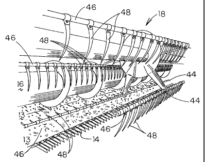
Referring to Figs. 1-3, there is shown a conventional combine 10.
Combine 10 has a header 13, a cutter bar 14, an auger 16, a bat drive 12 and a
reel assembly 18. To the rear of the reel assembly 18 is a cab 20, and behind
the cab 20 is an engine 22 and a grain bin 24 for the harvested crop 25.
Cutter
bar 14 is bounded at each end by dividers 26.
Referring to Fig. 2, there is shown the combine header 13, the combine
frame 34, the pivot bar 36 pivotally secured to frame 34. Bar 36 has opposite
ends 38, 39. End 39 of pivot bar 36 is pivotally secured to the bat reel
assembly 18. The opposite end 38 of pivot bar 36 is secured to frame 34. A
power cylinder 40 is shown interconnected between the frame 34 and the pivot
bar 36 whereby power cylinder 40 can be extended to raise the bat reel
assembly 18 into its upper position shown in Fig. 2 and retracted to lower the
13
i,i;,.; ;.
CA 02389513 2002-06-06
bat reel assembly into its operating position as shown in Figs. 3 and Sa. The
bat reel assembly 18 is driven by a chain 28 between motor sprocket 30 and a
bat reel sprocket 32. Chain 28 is shown in Fig. 1 covered by chain cover 33.
The above description describes almost every grain header
manufactured in the last 40 years. Each has a frame 34, a bat drive system 12,
a header 13, a cutter 14, an auger I6, a bat reel assembly 18, a cab 20, an
engine 22, dividers 26 and bat assembly drive sprockets 30, 32 and chain 28,
and all of the other structure above-described. Each of the various brands of
headers may differ in various minor respects, but in no respect critical to
the
invention described herein. The bat reel assembly 18, the augers 16, the
headers 13 and the cutter bars 14 may be provided in these combines in
different Lengths. However, the bat drive systems 50, 150, 200, 220 and 250
of the invention may be adapted in each case to replace the conventional bat
drive system 12 of each of these headers in manners fully known to those
skilled in the art of harvesting equipment.
Each of the bat reel assemblies 18 conventionally have a plurality of
circumferentially spaced apart bats 44 consisting of a bat rod 46, and in the
embodiment shown in the drawings, a plurality of spaced apart bat fingers 48
secured to the bat rod 46. In combines designed to harvest wheat and some
other small grains, these bats 44 will have instead of the fingers 48, a bat
trowel or paddle in the form of an elongated bat plate secured to the bat rods
46. These bat plates are not shown, however, as the bat reel assembly 18
rotates about its central axis each of the bat rods 46 rotate in the same
manner
14
~, .ii
CA 02389513 2002-06-06
as described herein to maintain the bat fingers or the bat plates 48 generally
vertically or perpendicular to the ground. In this manner, the bats 44 of the
reel assembly 18 always are correctly positioned to move crop into the cutter
bar 14 and across the header 13 into auger assembly 16. In general, the bat
drive system functions to rotate the rods 46 to maintain the position of the
bat
fingers or bat plates 48 in the desired generally vertical position as the bat
reel
assembly 18 rotates.
The new and improved bat drive systems 50, 150, 200, 220 and 250 of
the invention will be described. The new and improved bat drive systems 50,
150, 200, 220 and 250 are mounted between the bat sprocket 32 and the bat
assembly 18 as shown in Figs. 1 and 2 replacing the conventional bat drive
system 12 of the combine. The new and improved bat drive systems 50, 150,
200, 220 and 250 can be assembled on every combine made in the last 40
years by removing old bat drive system 12 and replacing the same with the
new bat drive system.
Refernng to Figs. 6-15, the new and improved bat drive assembly 50 is
shown to include a plate 52 to which bat drives 54 is secured by bolts 56. Bat
drives 54 are paired in diametrically opposite bat drive pairs. Traditionally,
three or four such pairs are positioned circumferentially spaced apart about
plate 52. The bat drives 54 extend diametrically outwardly of the plate 52. At
the distal end of each bat drive 54 is a bat clamp 58 which is pivotally
connected to one end 59 of a bat operating lever 60. The other end 61 of lever
60 is pivotally connected to bat rod 46. By bat operating lever 60, each bat
15
. .,.~.,;:,.fa.:- .'
CA 02389513 2002-06-06
rod 46 is rotated into and out of a folded position by the extension of the
cam
lever 72 of the bat drive 54 as will be described in more detail hereinafter.
Bat drives 54 are identical, and thus, a description of one will suffice
for all. Each of the bat drives 54 include two spaced apart plates 62 and 64
and a cover 66 as shown in Figs. 9, 10 and 11. Plates 62 and 64 are spaced
apart by spacers 68 to define a passageway 70 extending longitudinally of the
bat drive 54. Plates 62 and 64 and spacers 68 are secured together by spaced
bolts 69. Positioned within the passageway 70 is a bat cam lever 72. Bat cam
lever 72 has opposite ends 74, 76. Adjacent end 74 of the bat cam lever 72 is
bat clamp 58. Adjacent end 76, bat cam lever 72 is pivotally connected to cam
lever 78 by a pin 79. Pivotally mounted on the opposite sides of the bat cam
lever 72 on pin 79 are a pair of cam rollers 80, 81. Bat cam lever 72 adjacent
end 74 is wedge shaped having opposite cam edges 82, 84. Cam edges 82, 84
converge toward end 76 and extend between lever end 74 and cam edge end
86. Edges 82 and 84 are generally planar. Between end 76 and end 86,
opposite edges 82 and 84 are generally parallel to each other.
Bat cam lever 72 is movable between plates 62 and 64 and spacers 68
longitudinally of bat driver 54 to move clamp 58 between an extended position
88, shown in Fig. 9, and a retracted position 90, shown in Fig. 10. A slot 92
is
positioned in plate 64. Bat cam lever pin 79 is positioned in slot 92 with cam
rollers 80, 81 on opposite sides of plate 64 and with bat cam lever 78 on the
same side of plate 64 as roller 81. Pin 79 is allowed to move within slot 92.
Slot 92 has opposite ends 91 and 93. End 91 with pin 79 defines retracted
16
,~~v~:r .. I
CA 02389513 2002-06-06
position 90 of bat cam lever 72 and end 93 with pin 79 similarly defines
extended position 88 of bat cam lever 72 as pin 79 is at end 91 of slot 92
when
cam lever 72 is in its retracted position 90 and is at the other end 93 of
slot 92
when cam lever 72 is in its extended position 88. Pin ?9 is positioned in slot
92 and spaced apart from the opposite elongated sides thereof by bat cam lever
78 as will be mentioned hereinafter. This allows for bat cam lever 72 to move
longitudinally of slot 92 and of bat driver 54 without any restriction by pin
79
contacting plate 62 while moving in slot 92.
On the opposite side of plate 64 is mounted a spring 94 which
resiliently urges bat cam lever 72 into its collapsed position 90. Spring 94
is
extended between pin 96 which extends between plate 64 and cover 66 and
pin 98 which extends outwardly of bat cam lever 72. Plate 64 is cut away at
I00 to allow pin 98 to move between extended position 88 and collapsed
position 90 of bat cam lever 72. Edges 102, 104 of cut away 100 are generally
planar and sloped toward each other away from clamp 58 to guide pin 98 and
bat cam lever 72 into collapsed position 90.
Also positioned between plate 64 and cover 66 is lock lever 106. Lock
lever 106 is pivotally connected to plate 64 by pivot pin 108 which extends
between plate 64 and cover 66. Lock lever 106 moves between a locked
position 109 and an unlocked position 110. Spring 112 is provided to bias
lock lever 106 into its locked position 109 as shown in Fig. 11. Spring 112 is
connected between lock lever 106 and adjacent bolt 69. Bolts 69 secure plates
62, 64, spacers 68 and cover 66 together.
i7
~ ~ ,~ i ~
CA 02389513 2002-06-06
Referring now to Figs. 6-8, there is shown the new and improved bat
drive system 50 of the invention to comprise a plate 52 to which a plurality
of
bat drives 54 are secured so as to extend radially outwardly therefrom. Bat
drives 54 are secured in diametrically opposite pairs. Figs. 6-8 show the new
and improved bat drive system 50 of the invention to include three
diametrically opposite pairs, or a total of six bat drives 54. However, more
or
less pair may be used if desired. Each of the bat drives 54 are secured to
plate
52 by bolts 56. Adjacent each of the bat drives 54, plate 52 has a slot 120
therein which is sized and positioned so as to coincide with slot 92 when
plate
64 of a drive 54 is secured to plate 52 by bolts 56. Pin 79 is positioned
within
slots 92, 120 and cam rollers 80, 81 are positioned on opposite sides 116, 118
of plate 52 shown in Figs. 6 and 8. Inward of the combine drive flange 124
there is a cam plate 126 secured to drive flange 124 and a cam 128 secured to
each plate 126 by brackets 130. Plate 52 and bats 54 attached thereto are
mounted to plate 126 for rotation by cam rollers 132 which are positioned
within a drum 134 which extends inwardly of plate 126. See Fig. 8. Thus,
plate 52 and the bats drivers 54 attached thereto rotate about drum 134
relative
to flange 124, plate 126, drum 134 and cam 128. Each of the cam rollers 81 of
the individual bats 54 ride upon cam 128 as shown in Fig. 6. Both the bat cam
lever 78 and cam roller 81 is positioned on the side 118 of plate 52 opposite
cam 128. Cam lever 78 is secured to adjacent bat lever 54 about pin 56. Cam
lever 78 between pin 56 and pin 79 has a length equal to the radius of slots
92,
120. Thus, cam lever 78 pivots about pin 96 of adjacent bat driver 54 as bat
18
ii
CA 02389513 2002-06-06
cam lever 72 is moved between its extended 88 and retracted 90 positions so
as to keep pin 79 spaced between the opposite side surfaces of slots 92 and
120 and free of any binding within slots 92, 120.
A cover 136 is secured to drum 134 by bolts 13$ positioned coaxially
of cam rollers 132 to enclose drum 134 and to keep cam rollers 132 free of
foreign substances. Cover 136 has at its peripheral edge a cam 140 which cam
rollers 80 engage when cam rollers 81 are not engaged with cam 128. As will
be explained hereinafter, cam 128 maintains each of the bat drives in its
retracted position 90 and cam 140 controls the rate at which each of the bat
drivers 54 move against spring 94 into its extended position 88. See Figs. 7
and 11.
Referring to Figs. 16 and 17, a modified version 150 of the bat drive
system of the invention is shown. Like reference numerals will be used to
denote like parts. Bat drive system 150 is shown to be driven by a plurality
of
chains 152, 154, 156 instead of the two cams 128, 140. A central sprocket 158
is secured to drive flange 124 for each chain 152, 154, 156. Each of the
diametrically opposite bat drives 164 are driven by one of the chains 152,
154,
156 engaging one of the central sprockets 158.
Bat drives 164 are identical, and thus, a description of one will suffice
for all. Bat drive 164 comprises an end sprocket 165 and two pair 166, 168 of
sprockets linked together for common movement. Each sprocket pair 166,
168 has a movable sprocket 170 and a stationary sprocket 172. Stationary
sprocket 172 like end sprockets are each pivotally connected to plate 52 which
19
~~:-'i!=:
CA 02389513 2002-06-06
rotates relative to the central sprockets 158. Each of the movable sprockets
174 of sprocket pairs 166, 168 are pivotally connected to end 176 of a lever
178 having opposite ends 176 and 180. End 180 is pivotally connected to the
opposite ends of a rocker 182 which is pivotally connected to plate S2.
Rocker 182 midway between ends 176, 180 has secured to it a cam lever 184
which extends downwardly of the rocker towards sprockets 158. Cam lever
184 has a distal end 186 to which a cam roller I88 is pivotally connected.
Cam roller 188 is positioned on cam 190 which is secured to sprockets 1S8
and plate 126 and drive flange 124. A spring 192 is secured between rocker
182 and plate 126 to bias cam roller 188 against cam 190.
Thus, movable sprocket 174 of pair 166 acts as tensioning sprocket and
movable sprocket 174 of sprocket pair 168 functions as a timing sprocket. As
the timing sprocket is moved away from the stationary sprocket 172 of pair
168, the tensioning sprocket is moved closer to the stationary sprocket 172 of
pair 166 so as to maintain the tension of the chain as the accelerated
movement of the end sprocket 16S is accomplished to rotate the bat fingers as
described herein. As shown in Fig. 16, end sprockets 16S may be provided
with a cover 194 secured to plate S2 so as to minimize the fouling of end
sprocket 16S and the chains 152, 1 S4 and 156.
In a specific embodiment, sprockets 158, 16S each are provided with
thirty-six teeth and each of the sprockets of pairs 166 arid 168 are provided
with fifteen teeth to provide bat rod movement from about 1 to about 1.7
radians. In this embodiment 1 S0, whatever number teeth, the central sprockets
20
. ~. ~.;; ;ii
CA 02389513 2002-06-06
158 are provided with the end sprockets having the same number of teeth and
the bat rods 46 are each rotated one revolution as the bat assembly is rotated
one revolution.
As an added feature, in combines in which the bat fingers or bat plates
48 may become wrapped with cut crop stalks, a bat finger unwrapping
movement can be accomplished by providing end sprockets 165 with half the
number of teeth of central sprockets 158. In this embodiment, each bat rod
will accomplish two rotations for every single rotation of the bat reel
assembly
18 and diametrically opposite the rotation of the bat fingers 48 adjacent the
header 13, the bat rods 46 and the attached bat fingers 48 will rotate in the
opposite direction one full rotation to unwind crop stalks and to free them
from the bat assembly 18.
Refernng now to Fig. 18, a modified version 200 of the bat drive
systems 50 and 150 is shown. Like reference numerals will used to refer to
like parts. This version 200 is similar to version 150 illustrated in Figs. 16
and
17. The major difference between versions 150 and 200 is that version 150
includes three central sprockets 158 and three chains 152, 154 and 156 to
drive
the six circumferentially spaced apart bat drives 54. Like versions 50 and
150,
version 200 may have more or less bat drives 54. In version 200 illustrated in
Fig. 18, all six bat drives 54 are driven by a single chain 210, and adjacent
bat
drives 54 share a common stationary sprocket 172 of the sprocket pairs 166,
168, and thus, bat drives 54 may be supplied in even or odd numbers. The
cam lever 178 is shown to be pivotally connected to end 218 of rocker 182
2Z
i
CA 02389513 2002-06-06
instead of being secured at its midpoint. Additionally, chain reverse
mechanism 202 is shown to include sprocket 204 pivotally connected to plate
52 and movable lever 208 pivotally connected at one end to plate 52 by pin
212. Sprocket 206 is pivotally connected to lever 208 at its distal and
unattached end 218. Spring 214 biases sprocket 216 against chain 210. An
additional stationary sprocket 206 is pivotally connected to plate 52 adjacent
chain reverse mechanism 202. By being trained over sprockets 204 and 206
over central sprocket 158 and over sprocket 216, the chain is reversed in
direction.
In a specific embodiment of version 200, central sprocket 158 has forty
teeth, end sprockets 165 have forty teeth and stationary sprockets 172, 204,
206, 216 and movable sprockets 174 all have fifteen teeth. If it is desired to
provide bat rods 46 the crop stalk unwinding feature above mentioned with
regard to version 150, central sprocket 158 is provided with eighty teeth not
forty such that bat rods 46 complete two revolutions every time that the bat
reel assembly 18 completes one revolution. In specific embodiments of
versions 150 and 200, rocker 182 may be exchanged between versions.
Referring to Fig. 19 a third chain driven version 220 is shown. In this
version 220, each bat drive 54 is driven by a single chain 222 about a central
sprocket 158. Again, like reference numerals will be used to refer to like
parts, and any number of bat drives desired may be used if space permits.
Large sprockets 226 are pivotally connected to plate 52 between central
sprocket 158 and each end sprocket 165 by pin 224. Also pivotally connected
22
. , v~inlu~~ . ~~
CA 02389513 2002-06-06
to the plate 52 about pin 224 is cam lever 228 having a single sprocket pair
230 secured to one end 232 thereof. A cam roller 188 is pivotally connected at
the other end 234 of lever 228; Cam roller 188 is biased against the cam 190
by a spring 192. The sprockets 236 of pair 230 are pivotally connected to
lever 238 which extends transversely of lever 228 and end 232 and is secured
thereto.
In this version 220, in a specific embodiment, central sprocket 158 is
provided with thirty teeth, large sprocket 226 is provided with thirty teeth
and
end sprocket 165 is provided with thirty teeth.
Refernng to Fig. 20, another modified version 250 is disclosed. Again,
like reference numerals will be used to refer to like parts; and any number of
bat drives desired may be used if space permits. Modified version 250 uses a
fluid driven (hydraulic or pneumatic) cylinder 252 in each bat drive 54 to
move clamp 58 outwardly as in version 50. Bat clamp 58 is secured to the
distal end of the extendible and retractable rod of the cylinder 252. Attached
to the cylinder 252 is a fluid valve 254 which is opened and closed by a cam
roller 256 secured to the valve lever 258 of valve 254. As the cam roller 256
rolls on the cam 140, the valve 254 is opened forcing fluid into the cylinder
252 and extending the clamp 58. In order to guide the movement of the valve
lever 258, a guide lever 260 is pivotally connected to plate 52 at one end
261.
A cam roller 188 is pivotally connected to the opposite end 263 of lever 260.
A spring 266 extends around valve lever 258 to resiliently urge cam roller 256
23
,i . I, I I
CA 02389513 2002-06-06
against cam 190. Suitable fluid connections 264 are provided from the central
hub 262 to each of the valves 254 to provide fluid to power cylinders 252.
In operation, combine 10 functions as any other conventional combines
to harvest crop by moving against the crop. The crop is guided by the dividers
26 and the bat reel assembly 18 and the motion of the combine 10 toward the
cutting bar 14. Cutting bar 14 cuts the crop and lays the crop on the header
13. The bat reel assembly 18 rotates from a position ahead of the header 13 to
present the crop upstanding in front of the cutter bar 14 and to move the cut
crop across the header 13 and into the grasp of the auger 16. Auger 16 then
moves the cut crop into the harvester's grain bin 24.
The bat reel assembly is also conventional except for the bat drive
system 50, 150, 200, 220, 250 of the invention. Each of the bats 44 include a
bat rod 46 with either spaced apart bat fingers 48 secured thereto or a bat
plate
48 as above described. The bats are spaced apart circumferentially so as to
extend the full length of the bat assembly 18 with the bat rods 46 generally
parallel to each other and circumferentially spaced about the central support.
Each of the bat rods 46 are journaled for rotation relative to the bat reel
assembly 18. The bat reel assembly itself is journaled for rotation by the
drive
chain 28.
Each of the bat drive systems 50, 150, 200, 220, 250 of the invention
drive each of the bats 44 in essentially the same manner. As the bat reel
assembly 18 is rotated, each of the bat rods 46 is rotated to maintain the bat
fingers or the bat plates 48 generally vertically disposed toward the ground
as
24
N.. i ~' L... "i~i. . y,
CA 02389513 2002-06-06
is conventional. However, by the new and improved bat drive system 50, 150,
200, 220, 250 of the invention, the rotation of each of the bat rods 46 of the
bat
assembly 18 is rotated to position them spaced apart from the ground and in
front of the cutter blade are accelerated in rotation so as to move the bat
fingers or plates 48 from their essentially vertical position to fold the same
inwardly toward the combine so as to allow the bat fingers or plates 48 to be
positioned closely adjacent to the header until the bat fingers or plates 48
approach the auger 16 at which time the rotation is decelerated and reversed
to
position the bat fingers or plates 48 in their essentially vertical position
once
again. The accelerated rotation of the bat rods 46 allows for the header to be
cleaned by each bat 44 and to move grain continuously into the auger and into
the harvester's grain bin 24 at a more consistent rate. By this accelerated
motion of the bat fingers or plates 48 to fold them out of their generally
vertical position as they approach and move over the header 13, the crop is
more efficiently moved into the combine leaving the field essentially swept
free of cut crop more efficiently. Not only is the field cleaner of crop when
using the combine 10 of the invention, but the crop is fed more continuously
at
a more even rate into the combine. Conventionally, with combines of the type
to which the invention pertains, one can listen to repeated revs of the motor
as
the combine is moving across the field. The motor is accelerated and
decelerated repeatedly as the crop is fed into the processor. Since the crop
is
fed unevenly and not continuously, bunches of cut crop are fed into the auger
causing the motor of the combine to accelerate when little or no cut crop is
fed
Zs
i i ~ E,
CA 02389513 2002-06-06
into the combine between large clumps of crop. Surprisingly, the cut crop is
fed into the combine 10 of the invention so evenly by the invention, that the
engine is not noticeably accelerated or decelerated during operation and the
combine 10 will experience over a twenty percent fuel saving during use. In a
specific embodiment, the fuel saving will range between 20 and 30 percent of
conventional.
The folding of the bat fingers or plates 48 of each of the bats 44 as they
approach the cutter bar 14 and move over the header 13 is best illustrated by
reference to Figs. 3-5. Figs. 3 and Sa show the bats 44 as they approach the
cutter bar and move over the header in spaced apart relation with each of the
bat forgers or trowel maintaining its generally vertical position. This
conventional bat assembly moves the crop into the cutter bar but is so far
spaced from the header, allows crop to accumulate on the header and later to
be fed in bunches to the auger 16 causing the aforementioned
acceleration/deceleration of the combine engine as it passes over the field.
In
use, many times, the fingers or plates 48 of each of the bats 44 are spaced
from
the header from about 6 inches to about 15 inches to prevent the fingers or
plates 48 from breaking upon impact of the header as the header floats and
follows the contours of the field. See Fig. 5a in which the motion of the
finger
tips is shown by dashed line 270. Generally, header 13 may move between six
to twelve inches to accommodate irregularities in the field.
Figs. 4 and Sb illustrate how the fingers or plates 48 are folded as they
approach the cutter bar 14 and move in a folded condition over the header 13
26
~....I. I
CA 02389513 2002-06-06
and are then rotated into their generally vertical position as they pass
upwardly
adjacent to the auger 16. In this folded condition, bats 44 can be positioned
from about 2 inches to about 1 inch above the cutter bar without experiencing
finger breakage or bat damage. See Fig. 5b in which the motion of the finger
tips is shown by dashed line 272. By this movement of the fingers or plates 48
over the header and in front of the auger, the dead space 274 in front of the
auger in which cut crop usually accumulates is vastly reduced. With a
conventional bat system, the dead space 274 between the header 13 and the bat
reel assembly 18 may be from about 10 to about 15 inches. In a specific
embodiment in which the new and improved drive system for the bat reel
assembly of the invention is utilized, this dead space 274 in front of the
auger
16 may be reduced to 4 to 6 inches. With the bat fingers or plates 48
positioned that close to header 13, a floating header 13 may still strike the
fingers as the header 13 moves to accommodate irregularities in the field.
However, by the new and improved drive system for the bat reel assembly of
the invention each of the fingers or plates 48 are moved out of their at rest
position upon impact against the resiliency of springs 94, 192 and 266 in
versions 50, 150, 200 and 250, respectively. Thus, unless the bat fingers or
plates 48 are hit by the header 13 top dead center, no bat finger or plate 48
breakage will occur. The bats 44 in each of the embodiments of the invention
not only present the crop to the cutter bar in an upright condition, but
effectively and efficiently sweep the header clean of cut crop and present cut
crop to the feed auger in a continuous and even manner at a more constant
27
jm.
CA 02389513 2002-06-06
rate, thus accomplishing the higher efficiency of operation of the combine as
above described.
An additional benefit of the invention in Fig. 5b is that the fingers, in
the folded condition being about 2 inches to about 1 inch above the cutter
bar,
are also closer to the surface of the field such that the folded fingers are
able to
lift fallen stalks and grain from the ground for cutting by the cutter bar,
whereas if the fingers were at a height conventionally seen in a combine reel,
fallen stalks and grain on the ground would not be presented for cutting and
would go as Lost harvest. The folded fingers additionally comb through crop
to properly prepare and position it for cutting, whereas a combine reel not
having the present invention would simply rake through the crop.
Referring now to Figs. 6-8, the operation of bat drive system SO of the
invention will now be described. In this drive system 50, a plurality of
circumferentially spaced apart bat drives 54, which are fully illustrated in
Figs.
9-12, are secured to plate 52 which is secured to the bat assembly 18 and
rotates with the bat assembly 18. Each of the bat drives are spaced
circumferentially around the plates 52 to form diametrically opposite pairs of
bat drives as explained herein above. Each of the bat drives 54 has a bat cam
lever 72 therein which moves essentially radially outwardly of the plate 52
whenever the bat rod 46 of a particular bat is accelerated in rotation to fold
the
bat fingers or plate 48 inwardly toward the combine IO as above described.
Each of the bat cam levers 72 has at its distal end 74 a clamp 58 which is
secured through a operative lever 60 to the bat rod 46 of each bat. Thus, each
28
.. ;~ i.,.-. ..
CA 02389513 2002-06-06
bat rod 46 rotates in its conventional fashion to maintain the bat fingers or
plates 48 in a generally vertical position until the cam lever 72 is moved
into
its extended position 88 at which time lever 60 is rotated to accelerate the
rotation of bat rod 46 to fold the bat fingers or plates 48 inwardly of the
combine as above described.
Bat cam lever 72 at end 76, opposite the distal end 74 which is
pivotally connected to the bat operating lever 60, has cam rollers 80, 81
secured thereto on opposite sides thereof and a cam spacer lever 78. Cam
rollers 80, 81 are positioned on opposite sides of plate 52 to engage cams 128
and 140, respectively. Cams 128, 140 are secured to plate 126 which is
secured to the bat assembly drive flange 124 and thus, do not rotate with the
bat assembly 18. Thus, as the plate 52 rotates relative to the cam 128, the
cam
rollers 80 move on the cam 128 as shown in Fig. 6 to maintain each of the bat
cam levers in their retracted position 90 with the roller pin 79 adjacent end
91
of slot 92 in plate 64 and slot 120 in the plate 52 of the bat drive 54. Cam
rollers 80 are released from the cam 128 over about one quarter of each
revolution as shown in Fig. 6. The extension of the bat cam lever 72 of bat
drive 52 then is controlled by the engagement of cam roller 81 on cam 140
which is shown in Fig. 7. Cam 128 is generally coaxial of the axis of rotation
of plate 52, the cam 140 is not. Thus, cam 140 gradually moves the bat lever
72 and its secured clamp 58 at its distal end 74 radially outwardly of plate
52
to rotate lever 60 and to accelerate the rotation of bat rod 46 to fold the
bat
fingers or plates 48 inwardly of the combine 10 as above described. Cam 140
29
i
w .~:,~~.uriu r
CA 02389513 2002-06-06
is actually the peripheral edge of cover 136 which closes drum 134 and
encloses the rollers 132 which support plate 52 for rotation relative to plate
126 are positioned. The rollers 132 within the drum 134 are shown in Fig. 8
as the cover 136 and cam 140 are removed.
Lever 78 of each bat drive 54 is secured to the adjacent bat drive 54
and plate 52 such that it may rotate about its securance and maintain pin 79
on
which cam rollers 80, 81 are journaled midway between the opposite sides of
slots 92 and 120 so as to prevent any binding of the movement of cam rollers
80, 81 between the opposite ends of slots 92 and 120. Slots 92 and 120 are
arcuate and have a radius essentially equal to the length of cam lever 78.
Referring to Figs. 9-12, each of the bat drivers 54 is shown in detail.
Bat cam lever 72 adjacent its distal end 74 is triangular in shape having
opposite cam edges 82, 84 which guide the movement of lever 72 between its
extended position 88 shown in Fig. 9 and its retracted position 90 shown in
Figs. 10 and 11. Lever 72 moves between plates 62 and 64 and spacers 68
within passage 70. When lever 72 is extended, pin 98 which is secured to
lever 72 is engaged by lock lever 106 to secure lever 72 in its extended
position. Plate 64 is cut-away at 100 to allow lever 72 and its extended pin
98
to move into its retracted position 90. When extended pin 98 is not engaged
with lock lever 106, spring 112 returns lock lever 106 into its unlocked
position 110 as shown in Fig. 11. Spring 94 which extends between cam lever
pin 98 and mounting pin 96 maintains cam rollers 80, 81 in engagement with
cams 128, 140 throughout the movement of bat cam lever 72 between its
30
~ ~-'4 I 4 'e:
CA 02389513 2002-06-06
retracted position 90 and its extended position 88. Cam 140 also locks and
unlocks lock 106. Thus, as each bat driver 54 is moved from its collapsed
position 90 to its extended position 88, cam 140 urges cam lever 72 into its
extended position 88 by moving pin 79 from end 91 toward end 93 of slot 92.
As that motions continues, spring 94 is extended and pin 98 moves past lock
106 and thus as cam 140 allows bat cam lever 72 to retract pin 98 becomes
positioned within depression 142 of lock lever 106 and bat cam lever is locked
into position 88.
Cam 140 at the appropriate time moves bat cam lever 72 back into its
collapsed position 90 whereby lock lever 106 is urged by spring 112 back into
its unlocked position so as to free bat cam lever 72 which is then retracted
by
cams 140 and 128 into its collapsed position 90. By this movement of
extending bat cam lever 72 between its collapsed position 90 and its extended
position 88, the rotation of each bat rod 46 is accelerated by the operational
lever 60 pivotally secured to the securance clamp 58 at the end of each bat
cam lever 72 so as to rotate the bat fingers or trowels 48 as described
herein.
Referring to Fig. 20, version 250 is shown to have a cam lever 72
somewhat shortened and secured to the rod of a conventional fluid operated
cylinder 252. The operation of versions 50 and 250 are somewhat similar.
When cylinder 252 is actuated, bat cam lever 72 is extended into its extended
position 88. When cylinder 252 is not activated, bat cam Lever 72 is retracted
into its retracted position 90 by its bias. Bat cam lever 72 in this version
is
also connected to a clamp 58 which is secured to an operative lever 60 which
31
.. ~, ! ; ; d l I
CA 02389513 2002-06-06
is secured to bat rods 46 as above described. When a cylinder 252 is actuated
by fluid valve 254 actuating rod 258 extends radially toward the axis of
rotation of plate 52 and hub 262. Valve control rod 258 has a distal end to
which a cam roller 256 is secured and journaled around a pin which extends
through lever 260. Cam 140 of cover 136 thus actuates valve 254 to extend or
retract cam lever 72 thus moving valve lever 258 into its retracted position
allows fluid to flow into cylinder 252 to extend cam Lever 72 radially
outwardly. Likewise, the extension of valve lever 258 to its extended position
cuts off all fluid flow into valve 254 causing cam lever 72 to return to its
retracted position. Valve lever 258 is resiliently urged into its extended
position by spring 266. Valve 254 is connected to a fluid supply by hoses 264
as is conventional. A pressurized fluid supply is mounted to the frame 34 of
the combine 10 and is delivered to each cam driver through the hub 266 by
hoses 264 as shown in Fig. 20.
Versions 150, 200 and 220 are each chain driven bat drive systems of
the invention. In operation, version 150, as shown in Figs. 16 and 17,
utilizes
a single chain for each pair of diametrically opposed bat drives 164. Version
200, as shown in Fig. 18, illustrates use of a single chain to drive all six
bat
drives 164. Version 220, as shown in Fig. 19, illustrates the use of a
separate
chain to drive each of the bat drives 164.
Refernng now to Figs. 16 and 17 and embodiment 150, each of chains
152, 154 and 156 are trained about a central sprocket 158, respectively, which
are secured to plate 52 and drive flange 124, respectively. Each of the chains
32
.. ~~ . ~. : j.., ~: , e,
CA 02389513 2002-06-06
152, 154, 156 are trained about end sprockets 165 of diametrically opposite
bat drives 54 and sprocket pairs 166, 168 as shown in Figs. 16 and 17. Each
of the sprocket pairs 166, 168 has a movable sprocket which is connected by
sprocket levers 178 to rocker 182. Cam lever 184 of rocker 182 has at its
distal end 186 a cam roller 188 which travels along cam 190 which is also
secured to bat assembly drive flange 124. Thus, both sprockets 158 and cam
190 are stationary with respect to plate 52 and each of the bat drives 54
which
rotate relative thereto.
As the bat reel assembly 18 rotates, plate 52 rotates with each of the
bat drives 54 secured thereto. As the bat assembly 18 rotates, each of the bat
rods 46 rotate to maintain the alignment of fingers or plate 48 in their
generally vertical position. Each of the bat rods 46 are secured to end
sprockets 165 of their respective bat drives 54. With the movement of rocker
182 relative to the plate 52, each of the bat rods 46 rotate to maintain the
bat
angers or plates 48 in the generally vertical position above described.
Each bat 54 has a sprocket pair 166 and a sprocket pair 168. Each pair
has a stationary sprocket 172 which is pivotally secured to plate 52. Each of
the sprocket pairs 166, 168 also has a movable sprocket 174 which is pivotally
secured to a sprocket lever 178 which in turn is pivotally secured to rocker
182
allowing the movable sprocket 174 to move from a position adjacent
stationary sprocket 172 to a position remote from stationary sprocket 172 as
the rocker 182 rotates about its pivotal connection to plate 52 in response to
the cam roller 188 following the cam 190 and transmitting its position via the
33
CA 02389513 2002-06-06
cam lever 178 to the rocker 182. As one of the movable sprockets 174 is
moved away from its stationary sprocket 172 the other movable sprocket 174
is moved toward its stationary sprocket 172 to maintain the tensioning of the
chain about all of the sprockets 158, 165, 172, 174 of each bat drive 164.
As the bat reel assembly 18 rotates, bat plate 52 positions one of the
bat drives 164 and its respective bat 44 in front of the cutter bar 14 and the
cam roller 188 moves the cam lever 184 to rotate rocker 182 in order to move
the movable sprocket 174 of sprocket pair 166 apart from each other and to
move the movable sprocket 174 of sprocket pair 168 closer to each other to
accelerate the rotation of end sprocket 165 to fold the bat fingers or plate
48 of
the bat 44 inwardly toward the combine as above described. Similarly, as the
fingers or plate approach the auger 14, the rocker 180 is moved by the cam
roller 188 on the cam 190 in the opposite direction to decelerate the rotation
of
end sprocket 165 to reposition the fingers or plate 48 in its generally
vertical
position for the remainder of the rotation of the bat assembly.
Refernng now to Fig. 18, the operation of version 200 will now be
described. In this version, rocker 182 is provided with movable sprockets
secured to each end of the rocker 182 and a cam roller 188 pivotally connected
to the distal end of cam lever 184 which is partially secured to rocker 182 at
end 170 thereof. A stationary sprocket 172 is located between each pair of bat
drives 164 and a single chain is trained about a single sprocket 152 and
stationary and movable sprockets 172, 174. So that chain 152 does not reverse
the rotation of the end sprockets 165 of the six bat drives 164 shown in Fig.
34
i ~. i,:.:. ~:,. c .,..
CA 02389513 2002-06-06
18, the chain is trained around a chain reverse mechanism 202 which includes
stationary sprocket 204 and a movable sprocket 206 which is pivotally
connected to end 212 of lever 208. Lever 208 is pivotally connected to the
plate 52 by pin 212 and biased by spring 244 to maintain the tension of chain
210, stationary sprocket 204, movable sprocket 206 and stationary movable
sprockets 172, 174 of sprocket pairs 166, 168 and central sprocket 158. In a
specific embodiment of version 200, central sprocket 158 has forty teeth, end
sprocket 165 has forty teeth in the version in which bat rods rotate one
revolution for each revolution of bat reel assembly 18. In the version in
which
bat rods 46 rotate two revolutions for each revolution of bat reel assembly 18
to unwind cut crop from the bats 44, sprockets 158 will be provided with
eighty teeth.
Version 200 functions to accelerate the rotation of bat rods 46 in the
manner above described with regard to version 150 to fold fingers or plates 48
as they pass over header 13 in the same manner as above described, by cam
rollers 188 at the end of cam lever 184 rotating rocker 182 to accelerate the
rotation of end sprocket 165 as shown in Fig. 18.
Referring now to Fig. 19 and version 220 of the bat drive system of the
invention, the operation of version 220 will be described. In version 220, a
single chain 222 is utilized to drive each of the end sprockets 165. In this
version, there is a central sprocket 158 and a large mediate sprocket 226 for
each end sprocket 165. Thus, for each end sprocket 165, there is a central
sprocket 158 and a large intermediate sprocket 226 as shown in Fig. 19 with a
35
~: i.W"~ ~I
CA 02389513 2002-06-06
chain 222 trained about sprockets 158, 226, 165 and between a sprocket pair
230. Sprocket pair 230 has a pair of sprockets 236 pivotally connected to a
bar 238 which is secured to a cam lever 228 having at its distal end 234 a cam
roller 188. Cam roller 188 travels along cam 190 so as to move cam lever 188
which is pivotally connected to plate 52 on the same pin 224 as connects large
sprocket 226 to plate 52 so as to rotate the sprocket pair 230 to accelerate
and
decelerate the rotation of end sprocket 165.
In specific embodiments of each of the chain driven versions of 150,
200 and 220, the folding of the fingers or trowel 48 may be accomplished by
rotation out of the essentially vertical position of fingers or trowel 48
approximately 90°. Similarly, both the fluid power cylinder version 250
and
the mechanical version 50 when appropriate cylinders 252 and lengths of
operative levers 60 are chosen will rotate end sprockets 165 so as to position
fingers or trowel 48 at least 90° from their generally vertical at rest
position.
By the invention, a new and improved drive system for the bat
assembly of a conventional combine header is provided by which the bat
assembly is driven to properly present crops for cutting and the cut crops are
consistently and evenly fed into the auger. The bat assembly driven by the
new and improved drive system of the invention cooperates with the floating
header to provide improved feed into the auger and at the same time to reduce
bat finger breakage and combine down time. With the invention, cut crop is
fed into the auger at a more consistent rate and combine operational costs may
be reduced up to twenty percent.
36
CA 02389513 2002-06-06
While a specific embodiment of the invention has been shown and
described herein for purposes of illustration, the protection afforded by any
patent which may issue upon this application is not strictly limited to the
disclosed embodiment; but rather extends to all structures and arrangements
which fall fairly within the scope of the claims which are appended hereto:
37