Note: Descriptions are shown in the official language in which they were submitted.
CA 02390083 2002-06-07
TRACK ARRANGEMENT FOR SUPPORTING WALL STUDS;
METHOD; AND, WALL FRAMEWORK ASSEMBLY
Field of the Invention
' The present invention is directed to the field of building construction
S and more particularly to arrangements for assembling framework of buildings.
In a
preferred application, the invention particularly concerns a track system for
supporting wall studs, in a snap-fit manner.
Background of the Invention
A wide variety of arrangements have been utilized for the assembly
of walls. Many concern tracks positioned along the floor and ceiling, between
which are extended vertical studs. A variety of methods for providing
interaction
between the studs and the tracks, are known. Examples are provided in U.S.
patents
5,797,233; 5,660,012; 5,394,665; 5,222,335; 4,854,096; 4,805,364; 3,536,345;
and,
3,852,927.
In general, improvement has been sought with respect to such
systems, generally to better accommodate: manufacture of parts; ease of
installation; structural integrity of the resulting wall frame; and,
adaptability for use
under a variety of circumstances.
Summary of the Invention
A track arrangement for supporting frame members such as wall
studs is provided. The track arrangement can be utilized to provide framework
assemblies. A typical wall framework assembly utilizing principles according
to the
present invention includes: a floor track as characterized; a ceiling track as
characterized; and, at least one and typically a plurality of wall studs
extending
between the floor track and the ceiling track. The principles described can be
utilized in association with both load bearing walls and non-load bearing
walls.
Further the principles described can be applied in the context of a wall
having a slip
track, for vertical movement, between the ceiling track and the vertical wall
studs.
1
CA 02390083 2002-06-07
The principles described herein can be provided in a variety of forms.
In some, each track arrangement comprises more than one piece. In others, each
track arrangement comprises a single unitary integral piece.
A preferred track arrangement, for example, utilizable as either the
floor track or the ceiling track includes: a central extension; and, a pair of
sidewalls.
According to the present disclosure, a preferred stud clip assembly is
provided in the
track. The preferred stud clip assembly generally comprises a clip in each
sidewalk
formed integrally with the associated sidewall, typically through a die
cutting
operation. The preferred stud clip is centrally disposed in a sidewall, and
comprises
an extension bent inwardly and into a preferred configuration for engagement
with a
portion of a stud. In general, the preferred configuration is formed to
include: a
front cam surface which is engaged by a portion of the stud, during wall
assembly;
and, a central stud ridge receiver, which snaps over a portion of the stud
during wall
assembly.
1 S The principles of the present invention include track arrangements as
characterized, wall assemblies utilizing such track arrangements, and methods
of
assembling walls utilizing such components.
The principles of the present disclosure can also be applied to
framework besides wall framework. The structural features would be the same or
analogous.
Brief Description of the Drawings
Fig. 1 is a fragmentary schematic perspective view depicting a wall
framework assembly comprising a ceiling track, a floor track and vertical
studs
extending therebetween, in accord with the present invention.
Fig. 2 is an enlarged fragmentary schematic cross-sectional view
taken along line 2-2, Fig. 1.
Fig. 3 is a view analogous to Fig. 2, depicting a step of assembly.
Fig. 4 is an enlarged, fragmentary side cross-sectional view of a clip
member in one of the ceiling and floor tracks, of the arrangement of Fig. 1;
the view
of Fig. 4 being from line 4-4, Fig. 1.
2
CA 02390083 2002-06-07
Fig. 5 is a fragmentary, perspective view of a portion of the assembly
of Fig. 1, but depicting a first alternate clip member, to a clip member
depicted in
Fig. 1.
Fig. 6 is a fragmentary, perspective view analogous to Fig. S, but
depicting a second alternate clip member to that of Fig. 1.
Fig. 7 is a fragmentary schematic perspective view of an alternate
embodiment to the arrangement depicted in Fig. 1; the arrangement of Fig. 7
depicting a slip track variation.
Fig. 8 is a fragmentary, schematic, side elevational view of the
assembly of Fig. 1, depicted with a wall covering mounted thereon, to form a
standard wall.
Fig. 9 is an enlarged, fragmentary schematic side elevational view of
a portion of the wall assembly of Fig. 7, depicted with a wall covering
thereon.
Fig. 10 is an enlarged, fragmentary schematic perspective view
analogous to Figs. l and 7, depicting a second alternate embodiment to the
arrangements of Figs. 1 and 7.
Fig. 11 is an enlarged, fragmentary schematic perspective view of a
third alternate embodiment to the arrangements depicted in Figs. l, 7 and 11.
Fig. 12 is a top edge view of a clip arrangement useable in selected
alternate embodiments of the present invention.
Detailed Description
The Structural Components, Generally
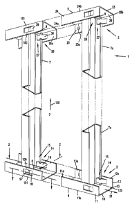
Reference No. 1, Fig. 1, depicts a framework assembly, specifically a
wall framework assembly in accord with the present invention.
In general, the wall assembly 1 according to the present invention
utilizes a unique track arrangement. In typical wall framework assemblies, two
track arrangements will be used: a first track assembly as a floor track; and,
a
second track assembly, as a ceiling track. In general, the preferred wall
framework
assembly concerns engagement between one or more wall studs, or other frame
members, and the preferred track arrangements.
Refernng now to Fig. 1, the preferred wall framework assembly 1
depicted includes a track arrangement 2 comprising: a ceiling runner or
ceiling track
3
CA 02390083 2002-06-07
and a floor runner or floor track 6; and, at least one frame member, in this
instance
stud 7, extending between the ceiling track 5 and the floor track 6.
(Actually, two
identical studs 7 and 7a are depicted.) For a typical wall framework l,
ceiling track
S and floor track 6 will be positioned in a building, to extend with the
ceiling track 5
5 positioned over the floor track 6. A variety of spacings for studs 7, 7a
could be
utilized, for example typically about 8 inches to 24 inches, inclusive, on
center,
depending on the wall.
The principles described herein for the wall framework 1 can be used
for load bearing walls and also for non-load bearing walls. For typical load
bearing
walls, one end 8 of each stud 7, 7a is bottomed out in the floor track 6, and
the other
end 9 of each stud 7, 7a is bottomed out in the ceiling track 5, so that the
studs 7, 7a
bear a vertical load force of the wall framework 1, i.e., the studs 7, 7a bear
vertical
load of the building. By the term "bottomed out" in this context, it is meant
that the
ends 8, 9 of the studs 7, 7a are pressed into and against the tracks S, 6,
with no
vertical space or gap therebetween.
For non-load bearing walls, it is not necessarily required that the
studs 7, 7a be bottomed out in the ceiling track 5. Reasons why it may be
desirable
not to bottom out studs 7, 7a in ceiling track 5 will be apparent from further
descriptions herein, relating to Figs. 7 and 9, and to application of the
principles
described herein with respect to wall frameworks in the context of a slip
track wall.
Still refernng to Fig. 1, the preferred floor track 6 depicted comprises
base or center extension 10, and first and second opposite sidewalls 11 and
12. In
general, the sidewalls 11 and 12 extend parallel to one another, with the base
or
center extension 10 therebetween. In general, a trough 13 defined by inside
surfaces
of the sidewalk 11 and 12, and an inside surface of the center extension 10,
will
sometimes be referred to as the "inside" of the floor track 6; thus trough 13
comprises the inside 13a of the associated track 6. In a typical small
framework
assembly, in which the stud 7 is bottomed out in the floor track 6 as
characterized
above, the end 8 of the stud 7 is inserted into trough 13 until that end 8
abuts center
extension 10.
In the previous paragraph, the trough 13 and inside 13a were
characterized as portions of "the associated" track 6. In this context, the
term
"associated" is meant to provide a shorthand way of identifying which of the
two
4
CA 02390083 2002-06-07
tracks, 5, 6, is being referenced; in particular the term "associated" means
the
portion on which the previously identified features (trough 13 and inside 13a)
are
- found. This abbreviated reference will be used in this disclosure, in an
analogous
manner, in other contexts.
Still refernng to Fig. 1, sidewalk 11 and 12 respectively include
outer edges 11 a and 12a. Herein the outer edges of 11 a and 12a of the
associated
ones of walls 11 and 12 are the edges remote from the associated extension 10.
The
sidewall edges 1 1b, 12b adjacent center extension 10 will be referred to as
inner
edges.
The floor track 6 includes, positioned on sidewalls 11, 12, stud clip
arrangements 14. In general, a typical floor track 6 will include a series of
stud clip
arrangements 14, spaced along the longitudinal extension of the floor track 6.
Each
stud clip arrangement 14 preferably comprises a pair of clips 15, each pair 15
comprising first and second clips, 18, 19 preferably positioned opposite to
one
another, on associated ones of sidewalls 11 and 12 respectively. By "opposite"
in
this context, it is meant that the clips 18 and 19 are preferably positioned
along the
longitudinal extension indicated by arrow 21, directly opposite from one
another
across center extension 10, generally as mirror images of one another.
In general, the preferred ceiling track 5 comprises analogous
components, i.e., base or center extension 23; associated first and second
opposite
sidewalls 24 and 25 having outer edges 24a, 25a and inner edges 24b, 25b and
forming, together with center extension 23, trough 26 defining inside 26a;
and, stud
clip arrangements 27 comprising pairs 28 of individual clips 29, 30. Indeed,
in some
preferred wall frameworks made according to the present invention, the ceiling
track
5 and the floor track 6 are generally identical, with respect to these
features, and are
simply mounted as mirror images, i.e., oriented in opposition. It is noted
that for the
particular wall framework 1 depicted, the ceiling track 5 and floor track 6
are
identical. With respect to this, and still refernng to Fig. 1, attention is
directed to
dimension Ll on floor track 6, and dimension L2 on ceiling track 5. Dimension
L1
indicates the depth of trough 13, i.e., the depth dimension of associated
sidewalls 11,
12; and, dimension L2 reflects the depth of trough 26, i.e., the depth
dimension of
associated sidewalls 24, 25. For the particular wall assembly 1 depicted in
Fig. 1,
L1 = L2.
S
CA 02390083 2002-06-07
As will be described below in greater detail, in some instances it will
be preferred to form a sidewall assembly in which L1 < L2. Such an assembly is
depicted in Fig. 7, described in detail below. This type of arrangement is
particularly useful for a wall having a slip track in a ceiling portion
thereof.
Refernng again to wall framework 1, Fig. 1, there is no specific
requirement that sidewalls 11 and 12 be identical (but oriented as mirror
images of
one another) nor is there such a requirement for sidewalls 24, 25. However, in
general, typical preferred constructions will be arranged in this manner. This
facilitates construction and use, as will be apparent from further
descriptions.
Attention is now directed to stud 7. A cross-sectional view of
arrangement 1 is depicted in Fig. 2, providing, among other things, a cross-
sectional
view of stud 7. Referring to Fig. 2, the stud 7 comprises a base wall or back
wall 36,
positioned between first and second, associated, longitudinal sidewalls 37 and
38. In
the preferred arrangement 1 depicted, the sidewalls 37, 38 are identical and
are
positioned as mirror images of one another.
In general, sidewall 37 includes an outer hanger wall 40 and an inner
projection ridge or stud ridge 41. The portion of sidewall 38 comprising
hanger wall
40 generally provides, among other things, a function of a structure or
surface on
which a wall covering can be secured. The preferred hanger wall 40 depicted
has
associated outer and inner surfaces 42, 43 that are both flat and extend
parallel to
one another.
Ridge 41 is positioned on, and directed away from, hanger wall 40
and allows for mechanical interaction with the stud clip arrangements 14, 27
to help
secure the stud 7 in vertical extension between tracks 5, 6, as described
below. A
preferred configuration for ridge 41 is as an extension or wall 44 projecting
from,
and typically orthogonal to, hanger wall 40, i.e., with angle 45 (Fig. 3)
being 90° and
angle 46 (Fig. 3) being 270°. Preferably, then, wall 44 (Fig. 3) has:
first and second
opposite surfaces 47 and 48 which are flat and extend parallel to one another;
and,
end edge 49, which is perpendicular to surfaces 47, 48 and generally parallel
to
hanger wall 40. Example dimensions for ridge 41 are provided below.
Referring again to Fig. 2, preferably sidewall 38 is a minor image of
sidewall 37, having outer hanger wall 50 and ridge S 1. Thus, preferably wall
50 is
6
CA 02390083 2002-06-07
parallel to wall 40, with outer and inner surfaces 52, 53 preferably flat and
parallel to
one another. Also, preferably ridge 51 comprises wall 54 projecting from, and
typically orthogonal to, hanger wall S0, with angle 55 (Fig. 3) being
90°, with angle
56 (Fig. 3) being 270°, with first and second opposite surfaces 57 and
58 extending
generally parallel to one another, and with end edge 59.
Referring again to Fig. 2, the particular stud 7 depicted has a base 36
that includes a recessed strip or center 60 and side trough sections 61 and
62. It is
noted that a variety of configurations for base 36 can be used in assemblies
according to the present invention, the particular configuration, comprising
recessed
center 60 and side sections 61, 62 merely being an example.
In preferred arrangements, the distance between outside surface 42
and outside surface 52, of stud 7, will be selected to provide a snug fit when
the stud
7 is positioned between sidewalk 11, 12 and sidewalk 24, 25, of the floor
track 6
and ceiling track 5, respectively. A preferred fit will be one which provides
for
1 S surface engagement, or a very slight gap, and no significant bow or bend
stress to
the various components S, 6, and 7.
It is noted that the tracks S, 6 and the studs 7, 7a may have various
apertures therein.
Components Providing for Preferred Interlock Fit Between the Wall Stud 7 and
the
Ceiling and Floor Tracks 5, 6
In general, the present disclosure provides for a preferred interlock
(connective) fit between the stud 7 and the ceiling and floor tracks S, 6.
When
employed in the form of the preferred embodiments depicted, the disclosed
principles provide for the following:
1. Standard frame members (studs) of the type depicted in Figs.
1 and 2 can be used, without modification, as the vertical wall
supports.
2. The frame members (studs) 7, 7a can be relatively easily and
safely locked in place at a construction site.
3. The tracks 5 and 6 are of the type which can be readily and
inexpensively manufactured and installed.
7
CA 02390083 2002-06-07
4. The wall framework is of a type that can be applied as
framework for either a load bearing wall or a non-load
bearing wall.
5. The principles can be applied as a slip track wall.
6. The interlock mechanism is such that although the frame
members (studs) 7, 7a can easily be locked in place, there is
significant resistance to removal of them once locked in place.
Attention is again directed to Fig. 2. In Fig. 2, at 70, interaction
between ridge 41 of stud 7 and an associated stud clip arrangement 14 is
depicted.
Analogously, at 71 interaction between ridge S 1 of stud 7 and an associated
stud clip
arrangement 14 is depicted. As a result of the two interactions at 70, 71, the
stud 7
is secured to floor track 6, between sidewalls 11 and 12.
Referring to Fig. 1, interaction between the stud 7 and the ceiling
track 5 would be analogous. That is, the cross-section shown in Fig. 2 would
have
an identical appearance, for the preferred embodiment depicted, if taken
directed
toward the ceiling track 5, as opposed to the floor track 6.
Referring to Fig. 2, the interaction between the stud 7 and the floor
track 6 depicted at 70, involves receipt of a portion of ridge 41 into
associated clip
18; and, the interaction at 71 concerns securing a portion of ridge 51 in
associated
clip 19. The interactions 70, 71, as shown in Fig. 2, for the preferred
embodiment
are generally identical and oppositely positioned.
Referring more specifically to interaction 70, the preferred clip 18 is
a bent extension 18a that includes the following features: front cam extension
75;
stud ridge receiver trough 76; and, rear spring extension 77. Operation of
these
components of clip 18, during assembly of wall framework 1, will be apparent
by
reference to Figs. 2 and 3. Specifically, during assembly, an end portion of
stud 7 is
positioned between sidewalls 11, 12 as shown Fig. 3. To provide locking
engagement, stud 7 is moved forward in the direction of arrow 81, toward the
associated pair of stud clips, causing ridge 41 to engage surface 84 of front
cam
extension 75, as shown. Continued movement in the direction of arrow 81, will
cause cam extension 75 to bow in the direction of arrow 86, and will also
cause
spring extension 77 to bow in the direction of arrow 87, i.e., away from
sidewall 11
and toward sidewall 12. As movement continues in the direction of arrow 81,
Fig.
8
CA 02390083 2002-06-07
3, eventually ridge 41 will encounter the stud ridge receiver trough 76, and
clip 18
will snap back toward sidewall 11 to the configuration depicted in Fig. 2.
This will
trap or lock a portion of ridge 41 in central receiver trough 76, securing
(locking)
this portion of stud 7 in place against unintended movement in the direction
of
double-headed arrow 89a, Fig. 2. An analogous, mirror image, engagement will
occur between ridge 51 and associated clip 19.
Since, for the preferred embodiment depicted, clip 19 and clip 18 are
oriented as mirror images of one another, and since stud 7 has symmetry (in
mirror
image) along its center, engagement between clip 18 and ridge 41 will
typically
occur simultaneously with engagement between clip 19 and ridge 51, as the stud
7 is
pushed in the direction of arrow 81. It is anticipated that at work sites, a
worker will
typically cause the motion of the stud 7 in the direction of arrow 81 to occur
by
kicking a lower portion of the stud 7 on rear surface 92.
From review of Figs. 1 and 4, preferred configurations of the clips or
clip members 18, 19 will be apparent. Refernng first to Fig. 1, for the
preferred
embodiment 1 depicted, each of clips 18 and 19 is integral with the associated
floor
track 6. By "integral" in this context, it is meant that the clips 18 and 19
are not
separate members attached to floor track 6, but rather are formed from
portions of
the associated sidewalk 1 l and 12 respectively, cut and bent in a preferred
configuration. Forming the clips 18 and 19 integrally with the track 6 in this
manner, facilitates manufacture and handling, as well as assembly and
structural
integrity.
Still referring to Fig. 1, in addition to being integral with the sidewall
in which it is formed, each of the clips 18, 19, is preferably centrally
disposed in the
sidewall with which it is integral. The meaning of the term "centrally
disposed" in
this context, can be understood by reference to clip 18, and sidewall 11, Fig.
1.
Specifically, refernng to Fig. 1, clip 18 is positioned spaced from both outer
edge
l la and inner edge l 1b of associated sidewall 11. Indeed, clip 18 is a
portion bent
inwardly of track 6 leaving open cut or four-sided frame 97. Thus, the term
"centrally disposed" is meant to indicate that the corresponding or associated
clip 18
defined, is not adjacent to an outer edge or inner edge of the sidewall with
which it
is associated, but rather, when integral, it is a portion of the sidewall (is
integral)
bent inwardly from a corresponding three-sided cut, leaving a four-sided
frame.
9
CA 02390083 2002-06-07
Preferably, the clip 18 is spaced, from a corresponding (associated) outer
edge 11 a
of the sidewall 11, by a distance of at least 0.25 inch, preferably a distance
within
the range of 0.25 inch to 0.75 inch, inclusive. Also preferably the clip 18 is
spaced,
from a corresponding inner edge 1 1b of sidewall 11, by a distance of at least
0.25
inch, preferably a distance of 0.25 inch to 8 inches, inclusive.
A benefit to providing the clip 18 "centrally disposed", is that in the
corresponding sidewall 11, there is left a lateral support extension 100,
positioned to
extend adjacent in associated stud 7, above (in the case of the floor track 6)
or below
(in the case of the ceiling track 5), the corresponding portion of the clip
arrangement
14. The lateral support extension 100 helps ensure a strong secure support for
the
stud 7, and thus structural integrity to the wall framework 1. Also a result
of being
"centrally disposed" is that there is left an associated lateral support
extension 101
positioned to extend adjacent and associated stud 7 below (in the case of the
floor
track 6) or above (in the case of ceiling track S), the corresponding portion
of the
1 S clip arrangement 14. The lateral support extension 101 also helps insure a
strong,
secure support for the stud 7 and thus structural integrity to the wall frame.
Herein, extension 100 will sometimes be characterized as extending
between associated or adjacent outer edge of the sidewall in which it is
positioned,
and the clip in (or on) that associated sidewall; and, lateral support 101
will be
characterized as positioned between the base or inner edge of the sidewall in
which
it is positioned, and an associated clip.
A particular preferred configuration for the clips 18, 19, is depicted in
schematic cross-sectional view in Fig. 4. Referring to Fig. 4, clip 18, in
associated
sidewall 11 is depicted. It will be understood however that the depiction of
Fig. 4
could be of any one of the clips in its associated sidewall. In Fig. 4, clip
18 is
depicted as it would appear in sidewall 11 prior to being engaged by a stud 7.
The
orientation and position depicted in Fig. 4 will be referred to herein as the
"memory"
or "rest" position of the clip 18. By the terms "memory position" and "rest
position"
in this context, reference is meant to a position the characterized clip 18
takes after it
has been formed to the sidewall 11 and prior to any engagement with a stud 7;
and,
as a result, it is the position to which the clip 18 attempts to return, if it
has not been
bent or sprung beyond a spring limit or elastic limit of the material from
which the
track 6 is formed.
CA 02390083 2002-06-07
Referring to Fig. 4, the clip 18, again, comprises a bent extension 18a
and includes front cam extension 75, central receiver trough 76 and rear
spring
extension 77. The front cam extension 75 includes a front surface 84 oriented
to
engage or contact stud 7, during assembly of wall framework 1. There is no
requirement that front surface 84 be planer; however for the particular clip
18
depicted, it is. In general, front surface 84 extends at an acute
(<90°) angle A1,
relative to wall 11.
Still referring to Fig. 4, in general, the clip 18 comprises a bent
extension 18a, having a free end 111. Herein the term "free end" when used in
reference to a bent extension 18a or a clip 18, is meant to refer to an end
remote
from a point of attachment 112 with an associated sidewall. Besides the free
end, in
general, the bent extension 18a includes a portion defining front cam surface
84 and
three bends 114,115,116, defining the central or stud receiver trough 76. The
stud
receiver trough 76 has a receiver opening 120, and the three bends 114,115 and
116
are oriented to direct the receiver opening 120 away from opposite sidewall 12
(Fig.
1) and toward an associated sidewall 11, specifically toward frame 97 in
associated
sidewall 11.
Herein, the front cam surface 84 will sometimes be referred to as
extending between free end 111 and stud ridge receiver trough 76.
In general, the three bends 114,115,116 comprise front bend 114,
center bend 115 and a rear bend 116; with the front bend 114 being the bend at
a
corner of the receiver trough 76 closest to free end 111; with the rear bend
116 being
at a corner of the receiver trough 76 furthest from the free end 111; and,
with the
center bend 115 being between the front and rear bends 114,116 and generally
forming an apex 118 of the receiver trough 76.
Herein, in some instances, each of bends 114,115,116 will be defined
with respect to its internal angle. The term "internal angle" when used in
association
with a bend, is meant to refer to the <180° angle (or side) of the
bend. Thus, for
center bend 115, the internal angle is the angle indicated at 125; for front
bend 114,
the internal angle is the angle indicated at 126; and for rear bend 116, the
internal
angle is the angle indicated at 127. Referring to Fig. 4, it is apparent the
bends
114,115,116 are not formed on a sharp crease, but rather are defined by
bending to
desired radii. When a dimension is provided for the angle, it is meant between
11
CA 02390083 2002-06-07
associated sidewalls, once a straight portion is reached, as indicated by the
locations
of the identifying lines for the angles, 125,126,127.
In typical preferred embodiments, center bend 125 will have an inside
angle within the range of 15° to 25°, inclusive, typically about
20 °; the front bend
126 will have an inside angle within the range of about 75° to
85°, inclusive,
typically about 80°; and the rear bend 127 will have an inside angle
within the range
of about 95° to 105°, inclusive, typically about 100°.
This configuration can be
readily obtained out of structural material from which tracks 5,6 are
typically
formed, i.e., 12-25 gauge, inclusive, (.0247-.1084 inch thick) galvanized
steel. The
term "inclusive" in this context is used to indicate that the end figures are
included in
the stated range.
In order to operate desirably as a cam extension 75, when a stud 7 is
engaged, in general, the following features are also preferred for the
configuration or
front cam extension 75:
1. End or tip 111 should be at a distance from sidewall 11
greater than a height of ridge 41 on a stud 7 to be engaged.
2. Angle A1, Fig. 2 of extension of surface 84 will typically be
at least 1 S~, and not greater than 30~, most preferably within
the range of 18° to 25°, inclusive.
In the event that surface 84 is not planer, in general the angle
corresponding angle A1 will be an angle of a plane defined by the portion or
portions of the surface 84 which will in fact engage or contact ridge 41,
relative to
the sidewall 11. Preferably surface 84 extends a length, between end 111 and
bend
114 at least 0.25 inch; typically a distance of 0.25 inch to 1 inch,
inclusive.
For typical arrangements angle A2, Fig. 4, will be on the order of
170° - 178°, inclusive, typically 171° -175°,
inclusive.
Still refernng to Fig. 4, in general to operate effectively as a central
receiver trough 76, the configuration of the central receiver trough 76 should
be such
that the sidewalk 130, 131 are spaced adequately apart, at least along a
portion of
their extension, to allow snug receipt of ridge 41 therein, during assembly,
Fig. 2. In
addition, sidewall 130 preferably extends at an angle, relative to sidewall
11, such
that once the ridge 41 is received, it is difficult for the stud to be pulled
back out of
12
CA 02390083 2002-06-07
the receiver trough 76, at least without the use of a tool to bend clip 18.
Also
preferably, the distance of projection of ridge 41 into central receiver
trough 76
should adequate to ensure a secure connection. Typically, the central receiver
trough 76 would be formed to allow for a depth of this extension inwardly, of
at
S least 0.1 inch, preferably at least 0.2 inch.
Turning attention now to rear spring extension 77, and referring to
Fig. 4, preferably the length of extension between point 142 on central
receiver
trough 76, and the hinge line 144, for rear spring extension 77 is adequately
long to
allow a spring extension to accommodate enough movement of front cam extension
75 for a convenient snap fit without the use of tools or special equipment,
but the
distance is preferably not so long as to weaken significantly the structural
integrity
of the sidewall 11. It is foreseen that with typical materials from which
tracks 5, 6
will be made in accord with the present invention, a distance of at least 0.75
inch,
not more than 1.5 inches, and typically about 1 inch to 1.25 inches will be
preferred.
In this context, reference to a hinge line 144 is meant to refer to the
point or line along which the clip 18 is bent inwardly from wall 11.
It is noted that the particular preferred engagement between the clip
18 depicted in Figs. 1 and 2, and the stud 7, is laterally fixed, i.e., fixed
to inhibit
unintended movement in the direction of the double-headed arrow 89, Fig. 2,
but it
is also vertically slidable, i.e., there is no interference at the clip 18
inhibiting sliding
movement in the direction of arrow 130, Fig. l, other than simply the extent
to
which the frictional engagement is snug. As a result, the stud clip
arrangement
described is easy to assemble and can even be utilized in association with a
slip track
wall, described in detail below.
Refernng to Fig. 5, a first alternate embodiment is depicted. In
particular, track 200 includes a clip arrangement 201 comprising clips 202,
203,
similar to clips 18, 19, except for the presence in clips 202, 203 of ridges
206. The
ridges 206 can extend from at or near end 207 to region 208 or further, and
provide
added strength in the region of the bends. The ridges 206 can be easily formed
during an operation to bend the clips 202, 203.
Refernng to Fig. 6, track 225 includes clips 226, 227, each of which
includes parallel ribs 228, 229. The particular arrangement shown, the ribs
228, 229
extend into a portion of the clips adjacent to the front or free ends 230. In
general,
13
CA 02390083 2002-06-07
ribs 228, 229 can extend from ends 231 as far into the bends as appropriate
and
desired to provide a modification to the strength or spring nature of the
various
bends.
The intent by provision of Figs. 5 and 6 is to show that a variety of
clip configurations alternative to the ones depicted in Figs. 1-4, can be
used.
Generation of a Framework for Non-Slip Wall, For Example a Load Bearing Wall
For a load-bearing wall, it is necessary for the stud 7 to be bottomed
out in each of the ceiling track 5 and the floor track 6. As a result, the
stud 7 bears
load without vertical ceiling movement. When the wall is a framework 1 is of
this
type, the ceiling track S and floor track 6 may, conveniently, be of identical
size and
dimension. A load-bearing wall is depicted in Fig. 1, with bottoming out of
the stud
7 in the tracks S and 6 as indicated.
It is noted that for a load-bearing wall, a convenient depth for the
troughs 13a, 26a, (i.e., dimensions L1, L2) is at least 1.5 inches to provide
for good,
strong, structural support, and typically not more than 3 inches, to avoid use
of
excess material, when the tracks 5, 6 are constructed from appropriate
structural
steel.
Even when the wall framework 1 is not load bearing, a construction
analogous to that described for a load bearing wall is convenient. That is,
typically
and preferably, except as described below for slip walls, the stud 7 will be
bottomed
out in the ceiling track 5 and the floor track 6, with the tracks 5, 6 being
identical
and as characterized.
Slip Track Walls
It is an advantage that the principles described herein can be applied
for the formation of slip track walls. In such walls, the ceiling track is
attached to
the roof or ceiling framework of the building, but the stud is not bottomed
out in the
ceiling track. As a result, as the ceiling height shifts in time, the ceiling
track 5 can
slide vertically along the stud. Various prior art slip tracks or slip walls
are
described for example in U.S. patents 5, 471,805 and 5,755,066, incorporated
herein
by reference.
14
CA 02390083 2002-06-07
A significant reason why the principles described herein are
applicable to slip walls, concerns the nature of the engagement between the
clip
arrangement and the stud. Specifically, the clip arrangement is configured so
that
while the stud is held securely with respect to horizontal movement, slide
connection
is provided between the stud and the clip arrangement.
The slip track wall framework is depicted in Fig. 7 at 300. In general,
wall framework 300 comprises floor track 301, ceiling track 302 and stud 307.
Floor track 301 includes clip arrangement 314 constructed and arranged
analogously
to clip arrangement 14, Fig. 1; and ceiling track 302 includes clip
arrangement 327
constructed and arranged analogously to clip arrangement 27, Fig. 1. The stud
307
generally has a configuration analogous to stud 7, Fig. 1.
Principal differences between the assembly 300 Fig. 7, and the
assembly 1, Fig. 1, result from dimension L2 in Fig. 7 being greater than
dimension
L1 in Fig. 7, as opposed to equal as indicated with respect to Fig. 1.
Otherwise, the
system is generally as described for Fig. 1.
In general, in order to utilize the principles of the present disclosure
in a preferred slip track wall, it is generally preferred that:
1. The stud 307 be bottomed out on the floor track 301 and;
2. The ceiling track 302 is spaced from the floor track 301 such
that when the stud 307 is engaged with the stud clip
arrangement 327 in the ceiling track 302, a space or gap 320
exists between end 321 of the stud 307, and the center
extension 323 of the ceiling track 302.
In general, for a desirable slip track, preferably when the wall frame
300 is assembled, the gap 320 should be at least about 0.25 inch, typically
within the
range of 0.25 inch to 8 inches, inclusive.
Again, when preferred arrangements of slip track walls are made by
using the principles described herein, the ceiling track 302 will typically be
configured such that it is deeper, in dimension L2, than is the floor track,
in
dimension L1. The extra distance allows, in a convenient manner, for the gap
320
between the end 321 of the stud 307 and center extension 323, without reducing
a
dimension of extension 340 between edge 341 and frame 342, relative to
extension
100 (Fig. 1) of ceiling track 5. Thus, the strength provided by extension 340
is
CA 02390083 2002-06-07
retained. It is not necessary to increase the depth of the floor track 301,
relative to
the floor track 6, Fig. 1, since slip at this location is not required, and
added extra
depth would merely increase weight and expense.
Covered Frameworks
Attention is now directed to Fig. 8. In Fig. 8, a wall 417 is depicted
in schematic, utilizing a wall framework 1 having a wall covering 420 mounted
thereon. The wall covering 420 may comprise a variety of constructions, the
particular one depicted comprising sheets of wall board 421, for example
drywall,
secured to hanger walls 40 of the studs 7, 7a by screws 423. The covering, 420
is
also shown secured to floor track 6, by screws 424. It is noted that the
particular
wall 417 depicted is not a slip wall, and thus wallboard 421 is also shown
secured by
screws 425 to ceiling track 5.
Attention is now directed to Fig. 9, which depicts, in a fragmentary
schematic view, a portion of a slip track sidewall, specifically a portion
adjacent a
building ceiling. In Fig. 9, a wall 435 having a slip track wall framework 436
is
depicted. In this instance, wall covering 440, again comprising sheets of wall
board
441 are secured to stud 7 by screws 445 (only one depicted). The wall board
441
would also be secured over a floor track, not shown, similarly to the wall of
Fig. 8.
However, in contrast to wall 417, Fig. 8, the wall covering 440 for wall 435,
although positioned to extend in covering relationship to a portion of side
451 of
ceiling track 302, is not secured to either the stud 7 or the ceiling track
302, in
regions that would interfere with sliding movement between the ceiling track
and the
stud 7 indicated at arrow 450. Thus, movement between the stud 7 and the
ceiling
track 302 is possible.
Some Selected Alternate Embodiments
Alternate applications of principles according to the present invention
will be apparent from the descriptions below in the context of Figures 10, 11
and 12.
First, it is noted that the track need not comprise a single integral
piece. That is, the sidewalk may be formed of separate pieces, separately
anchored.
An example of this is depicted in connection with the embodiment shown in Fig.
10.
16
CA 02390083 2002-06-07
Refernng to Fig. 10, a wall framework assembly 500 is depicted. The
assembly comprises a track arrangement SO1 and stud 502. The track arrangement
501 comprises a central extension 503 and first and second sidewalls 504 and
505.
The central extension 503 is formed from two separate pieces 510, 511. Other
than
S this modification, the assembly 500 of Fig. 10, is analogous to the
arrangement
shown in Figs. 1 and 7. Thus, this modification could be applied in connection
with
any of the arrangements previously described. The modification of Fig. 10
merely
indicates that the track can be split, for example along the central
extension, and
mounted as two pieces instead of one.
Yet another alternate application of the principles described herein
would involve utilizing only a single clip at each end, to secure each stud in
place, as
opposed to a pair of clips. Such a modification is depicted in the arrangement
550 of
Fig. 11. The wall framework arrangement 550 in Fig. 11 includes a track
arrangement 551 and a stud 552. The track arrangement SS1 comprises a central
extension 553, and first and second sidewalk 554 and 555. However, it is noted
that
there is only a single clip arrangement associated with stud 552; that clip
arrangement being depicted at 556 in wall 555. Thus, stud 552 is secured in
place in
track S51 by a single clip 556, as opposed to a pair of clips. Except for this
modification, the arrangement of Fig. 11 is analogous to the embodiments of
Figs. 1
and 7. Of course, the modification of Fig. 10 could be used in association
with the
arrangement of Fig. 11.
In Fig. 11 an alternate ridge 558 in clip 556, versus ridges 206 in clips
202, 203, Fig. 5, respectively, is shown. In the embodiment of Fig. 11, the
reinforcing ridge 558 in clip 556 extends only to bend 559. This ridge
construction
could be used in any of the embodiments described:
In all embodiments depicted in Figs. 1-11, the bent extension is
depicted as integral with a portion of the sidewall. Alternatively, the bent
extension
could be pre-made, and then be secured to the wall, for example, by welding.
Such
a non-integral (with the sidewall) bent extension could be secured to an
inside of an
associated sidewall, or it could be secured to an outside of an associated
sidewall,
with a portion projecting through an aperture of the sidewall. In Fig. 12, a
non-
integral bent extension 600 is depicted. It has a configuration similar to the
bent
extension 18a of Fig. 4, except it is a single separate piece that would be
attached to
17
CA 02390083 2002-06-07
a sidewall in use. The arrangement of Fig. 12, could be utilized in
association with
any of the various arrangements described above, for effective wall framework
assembly. The variation of Fig. 12 is to merely indicate that unless otherwise
stated,
there is no specific requirement that the clip be formed as an integral
component
with the sidewall, although, as indicated above, such is generally convenient
and
preferred.
Examples of Usable Materials and Dimensions; Examples of Component
Manufacture;
A typical, usable stud type, is the type sold by Members of the Steel
Stud Manufacturer's Association, as cold-formed steel framing members. Usable
studs are typically 8 feet to 40 feet long, inclusive.
Preferred studs will have a width of the hanger walls, i.e." horizontal
dimension, when stud is stood vertically, of at least 1.25 inches, typically
1.25 to 3
1 S inches, inclusive; and, an exterior height of ridge 41, Fig. 2, of 0.625
inch, with the
interior height of ridge 41, Fig. 2 resulting from the stud thickness.
For such typical standard studs, the width between opposite hanger
walls will typically be a standard dimension within the range of 1.625 inches
to 12
inches, inclusive, typically about 2.5 - 6 inches, inclusive. This dimension
will serve
to set or establish internal width of the preferred tracks.
Preferred tracks, whether floor or ceiling, will typically comprise
galvanized steel, for example 12 gauge to 25 gauge steel, inclusive. The
inside
width, will be chosen to match the width of the corresponding stud, typically
within
the range of 1.625 to 12 inches, inclusive, generally about 2.5 to 6 inches,
inclusive.
Preferred tracks will generally comprise three flat surfaces.
For typical systems, the distance between an outer edge, (for
example, edge 11 a) and an associated frame (for example, frame 97) is at
least 0.25
inch, typically 0.25-0.75 inch, inclusive.
Typically, the size of frame 97 will be about 2.5 inches long by 1.125
inches high.
A typical preferred clip would have dimensions as described
previously.
18
CA 02390083 2002-06-07
In general, the depth of a floor track, or ceiling track for a non-slip
wall, would be no more than about 2.5 inch, typically not less than about 1.25
inches. The depth of a ceiling track for a slip wall, would typically have an
added
depth of at least 0.5 inch, and generally not more than 8 inches, most
typically about
1 inch, relative to the depth of the floor track.
A variety of spacings for clips, longitudinally, along the ceiling track
and floor track can be used. An example would be to position a clip pair, on
center,
longitudinally spaced every 8 inches, along the length of the tracks.
The walls can be easily assembled by positioning a stud in the tracks,
and pushing it against the clips until the snap lock is obtained.
A variety of methods can be utilized to manufacture tracks in accord
with the present invention. The specific configuration is depicted in the
drawings,
can be readily made by bending elongate strips of metal, to form the three-
sided
track, and by using a punch and die arrangement, to form the individual clips.
Wallboard can be secured to the tracks and studs, in a variety of
conventional manners, for example, with screws. Any of a wide variety of types
of
wallboard can be used. Wall board can be selected for fire resistance, if
desired.
That is, wall frameworks assembled in accord with the principles described
herein,
can be used as firewalls.
It is noted that the principles described herein could be used in
structures other than walls. In such instances, the studs could be frame
members
extending between tracks, vertical and non-vertical orientations are, of
course,
possible.
19