Note: Descriptions are shown in the official language in which they were submitted.
CA 02390155 2002-05-03
WO 01/35015 PCT/IT99/00360
.1.
Cartridge connecting system for combustible gas
distributors"
DESCRIPTION
The subject of the present invention is a cartridge
connecting system for combustible gas distributors.
From International Application PCT WO 97/42446, for
example, combustible gas distributors are known, each of
which employs a plurality of single-use cartridges
containing the combustible gas. Said cartridges have
restricted dimensions and a limited capacity, for example
of the order of a litre. The distributor comprises a
plurality of connectors connected to a common manifold
which is in turn connected to a delivery device; each
cartridge is connected to a respective connector, and
valve members of the distributor provide for enabling or
otherwise the communication of one or more cartridges
with the delivery device. Each connector is provided with
a hollow needle which perforates the cartridge and thus
permits the flow of gas from inside the cartridge to the
delivery device through the valve members, or
alternatively the connector comprises a hollow pin which
opens a valve of the cartridge and permits the aforesaid
flow of gas from the cartridge to the delivery device.
Once they are exhausted, the cartridges are removed from
the respective connectors and replaced by new cartridges.
CA 02390155 2002-05-03
WO 01/35015 PCT/IT99/00360
.2.
In the simplest case, the distributor employs a
single cartridge housed in a suitable support provided
with a delivery device; the cartridge is coupled to the
delivery device by way of a connector provided with a
needle or pin exactly as seen above in the multi-
cartridge distributors. Said simple distributor is
provided, as is well known, in portable apparatuses such
as, for example, gas stoves with single burner or gas
lamps.
In the above-mentioned distributors with single
cartridge or several cartridges, the cartridge is coupled
to the connector by screwing.
However, the screw coupling is such that the user has
to give several turns to the cartridge to secure it to or
detach it from the connector. That is clearly laborious,
especially in the case of the distributor with several
cartridges.
Moreover, the length of the rotation action may cause
the operator not to reach the end of the travel, so that
the seal between cartridge and connector may be imperfect
and the anchorage of the cartridge to the connector may
be unstable.
Aim of the present invention is to remedy the
aforesaid drawbacks.
That aim is fulfilled by means of a cartridge
CA 02390155 2002-05-03
WO 01/35015 PCT/IT99/00360
.3.
connecting system for combustible gas distributors,
wherein the connector is connected to a delivery means of
the distributor and wherein the cartridge is detachably
secured to the connector, characterized in that the
cartridge is secured to the connector by a bayonet
coupling.
The invention will become clear from the following
description of one of its non-limiting exemplary
embodiments, in which:
Figure 1 is an exploded perspective view of a
cartridge connecting system for combustible gas
distributors according to the invention;
Figure 2 shows an enlarged detail of the system in
Figure 1;
Figure 3 shows the detail of Figure 2 in a mounted
configuration and partly in section;
Figure 4 shows according to another perspective
angle, and partly in section, the bottom of the cartridge
in Figure 1;
Figures 5 to 13 show, in axial section, valve members
of the system in Figure 1 in various operating states.
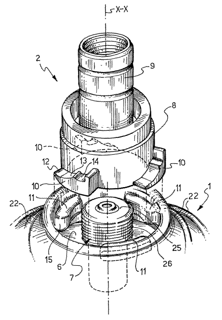
Figure 1 illustrates a cartridge 1 adapted to be
charged with combustible gas and intended, together with
other identical cartridges, to be used in a combustible
gas distributor, not shown; in said drawing there is
CA 02390155 2002-05-03
WO 01/35015 PCT/IT99/00360
.4.
further illustrated a connector 2 for the cartridge 1,
adapted to be incorporated in the distributor together
with other identical connectors for the other cartridges.
The cartridge 1 is formed of a cylindrical container
3 with base 4 of smaller diameter and of a hemispherical
dome 5 which closes the container 3 at the top. At the
vertex of the dome 5 there is provided a hollowed-out
cylindrical seat 6, in which is axially inserted a valve
7. Round the seat 6, in proximity thereto, a series of
concentric circular ribs 22 is provided.
The connector 2 provides a hollow connecting head 8
and a hollow shank 9 which extends from the head 8. The
shank 9 is internally threaded to be fixed by screwing,
together with the other connectors, to a manifold of the
distributor, connected in its turn to a delivery device
of the latter. The head 8 is adapted to be received in
the seat 6 of the cartridge 1.
The cartridge 1 and the connector 2 are coupled by
means of a bayonet coupling. To produce the bayonet
coupling, as shown in detail in Figures 2 and 3, the head
8 of the connector 2 provides an annular series of
projections 10 and, correspondingly, the seat 6 of the
cartridge 1 has an annular series of reliefs 11, each of
which couples with a respective projection 10 of the
connector 2. In particular, each projection 10 of the
CA 02390155 2002-05-03
WO 01/35015 PCT/IT99/00360
.5.
connector 2 provides a surface for contact with a
respective relief 15 of the cartridge 1, and said contact
surface comprises, in succession, a first portion 12
lying substantially in a plane perpendicular to the axis
X of the connector 2 , a second portion 13 inclined with
respect to said plane, and a third portion 14 shaped as a
recess; each relief 11 of the seat 6 of the cartridge 1,
on the other hand, provides a shaped engagement portion
adapted to be inserted into the recess portion 14.
10 With reference to Figure 5, the valve 7 of the
cartridge 1 comprises a cup-shaped body 16, the bottom of
which has a hole 17 which places the inside of the
cartridge in communication with the inside of said body;
above, the body 16 is closed at the top by a gasket 18
15 having a central hole 19 which permits the access of a
suitable member to the inside of the body as will be seen
hereinafter. In said body 16 there is received a hollow
closure means 20 held pressed against the gasket 18 by a
spiral spring 21, a portion of which partly wraps round
the closure means. The spring 21 has a constriction 23 in
which a ball 24 is retained.
The body 16 of the valve 7 is received in a hollow
cylindrical portion 25 of the dome 5, which substantially
represents a sort of outer jacket of the valve itself.
The portion 25 has on the outer lateral surface a thread
CA 02390155 2002-05-03
WO 01/35015 PCT/IT99/00360
.6.
26 and has an upper part which locks the gasket 18
against the opening of the body 16; said upper part has
a hole 27 aligned with the hole 19 of the gasket 18.
The dome 5 is rigidly connected to the container 3 by
means of double seaming.
With reference to Figure 4, the bottom 28 of the
container 3 has a convexity towards the inside of the
container itself. Moreover, the lower edge 29 of the base
4 of the container 3 is formed into a kerb by means of
l0 suitable folding back of the connecting portion between
base 4 and bottom 28.
With reference to Figure 10, the connector 2 houses
inside its hollow head 8 a pin 30 integral with the head
itself. In the pin 30 is provided an axial conduit 31
which communicates on one side with a transverse hole 32
provided at one end of the pin and leading into the
cavity of the head 8 ; on the other side the conduit 31
communicates with a conical seat 34 provided also in the
pin and opening into the cavity of the shank 9. In the
seat 34 is received a ball closure means 35. In the
cavity of the head 8, at the level of the pin 30, there
is housed a sealing ring 36. In the shank 9 is provided a
diaphragm closure means 37 held resiliently against a
seat 38 by a spiral spring 39 anchored to the inner wall
of the shank. Moreover, in the shank 9, at the level of
CA 02390155 2002-05-03
WO 01/35015 PCT/IT99/00360
.7.
the seat 38 in an opposed position with respect to the
seat 34 of the pin 30, a further conical seat 40 is
provided, adapted to receive the ball 35 under certain
operating conditions, as will be seen hereinafter.
The operation of the cartridge connecting system
described above is as follows.
First of all, with reference to Figures 6 and 7, the
combustible gas is loaded into the cartridge by means of
a suitable apparatus of known type, not illustrated as a
whole, which comprises a charging nozzle A having
internally an axial conduit B which communicates at the
end of the nozzle with a transverse hole C leading to the
outside. For charging (Fig. 6), the nozzle A is inserted
into the aligned holes 27 and 19 of the valve 7 of the
cartridge (indicated in Fig. 5) so that said nozzle is
inserted partially into the hollow closure means 20 of
the valve 7 and moves it away from the position of
closure of the valve 7 against the action of the spring
21. At this point, the combustible gas is caused to flow
from the charging apparatus into the cartridge through
the conduit B and the hole C of the nozzle A, the inside
of the body 16 of the valve 7, and the hole 17 of said
body. Once the cartridge is charged with combustible gas,
the nozzle A is inserted further into the valve 7 until
the closure means 20, pushed downwards by the nozzle,
CA 02390155 2002-05-03
WO 01/35015 PCT/IT99/00360
.8.
disengages the ball 24 from the constriction 23 of the
spring 21 (Fig. 7). Once it is disengaged, the ball 24
moves into the hole 17, and at this point the nozzle A is
extracted from the holes 19 and 27 of the valve 7 and the
spring 21 returns the closure means 20 to the position of
closure of said holes.
With reference to Figures 2 and 3, to connect the
cartridge 1 to the connector 2, the cartridge is
positioned on the connecting means so that the hollowed-
out seat 6 of the cartridge is placed on the head 8 of
the connecting means with the projections 10 of the head
arranged on the bottom of the seat 6 of the cartridge in
the spaces between the reliefs 11 of said seat. At this
point the cartridge 1 is rotated in a clockwise direction
about the axis X with respect to the connector 2 so that
the projections 10 wedge between the reliefs 11 and the
bottom of the seat 6 of the cartridge, and each relief 11
is engaged with a respective projection 10 owing to the
insertion of the shaped engagement portion 15 of the
relief 11 into the recess portion 14 of the projection 10
(Fig. 3). The portions 12 and 13 of the projections 10
constitute lead-in sections for the engagement. As shown
in Figure 11, when the head 8 of the connector 2 enters
the seat 6 of the cartridge 1, the inner pin 30 of the
connector is inserted into the holes 19 and 27 of the
CA 02390155 2002-05-03
WO 01/35015 PCT/IT99/00360
.9.
valve 7 (indicated in Fig. 5) and moves the closure means
20 away from the hole against the action of the spring
21, said pin 30 acting like the nozzle A in the charging
phase. The resilient force exerted by the spring 21 on
the closure means 20 is transmitted, through the pin 30,
to the connector 2 and tends to move the connector away
from the cartridge 1; consequently the projections 10 and
the reliefs 11 are pressed against one another by said
resilient force which maintains them in said engagement
position. The sizing and the arrangement of the
projections 10 and of the reliefs 11 are such that the
angle of rotation necessary for connecting the cartridge
1 to the connecting means 2 is about 60°.
With reference to Figures 8 and 11, once the
cartridge 1 is connected to the connector 2, the
combustible gas flows from the cartridge to the
connecting means through the inner hole 17 of the valve
7, through the inner part of the valve itself, and then
through the hole 32 and the conduit 31 (both indicated in
Fig. 10) of the pin 30 of the connecting means; the ball
24 is pushed by the gas pressure against the constriction
23 of the spring 21. From the connector 2 the combustible
gas flows into the distributor, lifting the ball valve 35
from its seat 34 and lifting the diaphragm valve 37 from
its seat 38 against the action of the spring 39.
CA 02390155 2002-05-03
WO 01/35015 PCT/IT99/00360
.10.
In the normal flow of combustible gas from the
cartridge 1 to the connector 2, the ball 35 remains
suspended in an intermediate position between the seat 34
and the opposed seat 40 of the connector and functions as
a flow limiter.
In the event that the pressure of the combustible gas
issuing from the cartridge 1 is excessive, as shown in
Figure 12, the ball 35 is pushed by the actual pressure
of the gas against the seat 40 of the connector 2 so as
to prevent the flow of gas under over-pressure to the
distributor.
In the case where the cartridge 1 and the connector 2
are accidentally turned upside down, as shown in Figure
13 the ball valve 35 fits against the seat 40, preventing
the combustible gas, and in particular its liquid phase,
from reaching the distributor.
As shown in Figures 11, 12 and 13, the gasket 36 is
interposed between the outer jacket of the valve 7 of the
cartridge 1, i.e. the cylindrical portion 25 (indicated
in Fig. 5) of the dome 5, and the inner wall of the head
8 of the connector 2, so as to prevent the escape of gas
to the outside when the cartridge is connected to the
connector, in addition to the gasket 18.
When the cartridge 1 is discharged, for replacement
it is disconnected from the connector 2 by rotation in
CA 02390155 2002-05-03
WO 01/35015 PCT/IT99/00360
.11.
the anti-clockwise direction of the cartridge with
respect to the connector, followed by removal from the
connector. The angle of anti-clockwise rotation is of
course about 60°, or equal to and of opposite direction
to the angle of rotation for the connection of the
cartridge 1 to the connector 2. During disconnection of
the cartridge from the connector, the pin 30 of the
connector emerges from the valve 7 and the hollow closure
means 20 returns to the valve closure position (Fig. 5).
As will be understood from Fig. 10, once the
cartridge is disconnected from the connector 2, if there
is pressurized combustible gas present in the distributor
coming from other cartridges, this cannot escape from the
connector owing to the diaphragm closure means 37
maintained by the spring 39 in the position of closure of
the passage of gas inside the shank 9 of the connector.
If for some reason the diaphragm closure means 37 does
not provide a seal, the gas would then be blocked by the
ball 35 which the actual pressure of the gas would
maintain against the seat 30 of the connector, preventing
communication between the inside of the shank 9 and the
inside of the head 8, and therefore the escape of gas
from the connector.
Once discharged, the cartridge 1 must be discarded
and cannot be re-filled. As illustrated in Fig. 9, if an
CA 02390155 2002-05-03
WO 01/35015 PCT/IT99/00360
.12.
attempt is made to re-fill the cartridge by inserting a
nozzle, still indicated by A, of a charging apparatus,
the pressure of the gas which enters the valve 7 pushes
the ball 24 into the hole 17 so that the latter is
obstructed and the gas cannot flow inside the cartridge.
The cartridge connecting system described above has
various advantages.
First of all, the connection seen between cartridge 1
and connector 2 proves to be particularly simple, rapid
and efficacious in that a minimal rotating action is
required for connection, and moreover the engagement
between the projections 10 of the connector and the
reliefs 11 of the cartridge guarantees a high stability
of connection and therefore reliable sealing.
Preferably, the angle of rotation for the connection of
the cartridge to the connector is not more than 60°.
As can be seen, the ball closure means 35 and the
diaphragm closure means 37 of the connector 2 guarantee
maximum safety with the cartridge detached, preventing
escapes of combustible gas from the connecting means;
moreover, the ball closure means 35 guarantees further
security by preventing the flow of gas under over-
pressure or in liquid phase to the distributor; and
finally the ball closure means 35 advantageously
functions as a flow limiter.
CA 02390155 2002-05-03
WO 01/35015 PCT/IT99/00360
.13.
The ball 24 of the valve 7 of the cartridge 1, as can
be seen, prevents fraudulent re-filling of the discharged
cartridge.
It should be added that both the structure of the
cartridge 1 and the structure of the connector 2 are
simple and therefore constructionally economical. In
fact, the body of the cartridge 1 is formed of only two
parts, i.e. the cylindrical container 3 and the dome 5;
the valve 7 of the cartridge and the connector are also
formed of few parts. A part of the dome 5, the hollow
cylindrical portion 25 forms, as can be seen, the outer
jacket of the valve 7. The other components of the valve
7 can be mounted simply in said cylindrical portion 25.
The fact that the cartridge 1 is produced in only two
parts double seamed to one another makes it possible to
make it very resistant to the stresses due to the
pressure of the combustible gas which is loaded into it.
The concentric circular ribs 22 of the dome 5 increase
the robustness of the dome itself at the level of the
connecting area, where the stresses are particularly
accentuated. The kerbed edge 29 of the base 4 of the
cartridge increases the robustness of the base itself.
The base 4 of smaller diameter allows the cartridge
to be grasped and easily connected to the connector
without interfering with the other adjacent cartridges
CA 02390155 2002-05-03
WO 01/35015 PCT/IT99/00360
.14.
mounted in the distributor.
The thread 26 of the outer jacket 25 of the valve 7
of the cartridge 1 makes it possible to connect the
cartridge itself to conventional screw connectors.
It is clear that variants and/or additions to what is
described and illustrated above may be provided.
The general configuration of the cartridge and of the
connector may vary.
It is possible to provide bayonet coupling elements
of the cartridge connecting system with functions
equivalent to the elements described and illustrated
above, even though the latter have proved particularly
simple and reliable.
The hollow closure means 20 and the diaphragm closure
means 37 may be replaced by closure means of various
configurations having the same function.
The closure balls 24 and 35 may also be replaced by
closure elements performing the same function, for
example pistons guided in suitable seats.
The cartridge connecting system seen above may of
course be applied also to a distributor provided with a
single connector and therefore employing a single
cartridge. Said system proves to be particularly
indicated however for multi-cartridge distributors, given
the rapidity of fitting the cartridges onto the
CA 02390155 2002-05-03
WO 01/35015 PCT/IT99/00360
.15.
connectors of the distributor.