Note: Descriptions are shown in the official language in which they were submitted.
i ~ I i~~, a ~ ,~I
CA 02390272 2002-06-11
r '
1810-0019
MOLDED DECK BOARD
BACKGROUND OF THE INVENTION
The present invention relates to cargo handling structures, particularly
deck boards. More specifically, the invention concerns a plastic molded deck
board that forms a surface for supporting cargo on top of trailer load beams.
To fill a cargo trailer to the load weight limit, cargo often must be
stacked more than one pallet high. To facilitate stacking without damaging
cargo, load beams can be mounted horizontally in a trailer, just above the top
of floor loaded cargo. Deck boards for supporting additional cargo can then
be placed on top of the load beams.
Deck boards that are sized and equipped for placement on trailer load
beams are generally constructed of wood. Use of wood or plywood and the
resulting design and construction presents many disadvantages. For
example, deck boards constructed of wood closely resemble cargo pallets, so
they are easily misused or misplaced. Theft is common since wood deck
boards can be disassembled and the wood used for another purpose. The
wood used for constructing deck boards is also susceptible to damage, from
use and outdoor storage, including splintering, cracking, warping, and
breaking. Since wood deck boards are necessarily constructed of multiple
components, fasteners or glued joints used to assemble components are a
point of potential degradation and failure.
The cost of wood has generally escalated in recent decades, making
manufacture of deck boards expensive. The weight of the wood necessary to
construct a sufficiently strong and durable deck board is greater than the
weight of certain other materials. When using wood, individual components
must be assembled and handholds, cargo strap holes, and anchor points
must be individually milled through the wood.
CA 02390272 2002-06-11
1810-0019
In light of the shortcomings of prior deck boards, there remains a need
for a single piece deck board that is sturdy, durable, and lightweight. The
deck board should be economically manufactured, readily identified, and
easily and safely handled.
2
i ni a
CA 02390272 2002-06-11
1810-0019
SUMMARY OF THE INVENTION
Briefly describing one aspect of the invention, the deck board
comprises a rectangular platform having a substantially flat front face and a
plurality of raised ribs on the bottom face. The platform is sized and shaped
for placement on trailer load beams, the raised ribs being sized and shaped to
form channels for receiving the load beams and for restraining movement of
the deck board relative to the load beams.
The difficulties with prior deck boards are overcome in one aspect of
the current invention by forming the deck board from molded plastic rather
than the typical composition of wood. Plastic composition differentiates the
deck board from commonly misused and misplaced pallets. The composition
also makes theft less likely than for easily dismantled wood deck boards.
Identification of ownership and use can be improved further by mixing specific
color dyes with the plastic and also by molding a company logo or use-
identifying design into the deck board.
A deck board constructed of plastic is also more resistant to
splintering, cracking, warping, and breaking, and does not require fasteners
or
glue joints that may fail, making it virtually unbreakable. To further
strengthen
the deck board, the side faces formed by all features can be rounded to
distribute stress points. In a further aspect, the four 90° corners of
the
platform can be truncated into a notch and two 135° corners. Raw
material
costs and standard molding techniques, such as rotational molding or blow
molding, which forms all features into the deck board in a single action, make
the manufacturing of the invention more economical than that of a wood deck
board.
In a further aspect, the deck board can be easily and safely handled
with a plurality of handholds that can be molded into the platform. The
plurality of handholds can also be used for cargo straps that secure the cargo
to the deck board or the deck board to the cargo trailer. To further secure
cargo, the top surface can be molded with nodular protrusions to increase
3
n '~ni n
CA 02390272 2002-06-11
1810-0019
friction and make the top resistant to skidding. To secure the deck board, a
plurality of retainer holes can be defined along the periphery of the platform
so that the deck board can be secured to the load beams or adjacent deck
boards.
In another aspect of the invention, the deck board has a pattern of
raised ribs on the bottom face that form channels on the centerline of both
axes of the bottom face. The raised ribs can also form shoulders along the
perimeter of the bottom face. The channels and shoulders are preferably
configured for receiving the load beams upon which the deck board rests,
with one beam located in the center and one located on each of at least two
opposite sides. With the deck board positioned on the load beams in this
manner, the ribs cooperate with the load beams to retain the deck board on
the beams.
Another feature of the invention is constituted by a plurality of bores
that extend from the top face through to the bottom face. The bores have
interior cylindrical walls connecting the top face to the bottom face to
increase
the rigidity of the deck board. The bores are preferably located in the
channels where the weight of the cargo is transferred from the deck board to
the center load beam.
In another embodiment of the present invention, a deck board
comprises a stackable platform for fitting in a cargo trailer. The platform
defines a top face for supporting cargo, a plurality of side faces extending
along a perimeter of the platform, and a bottom face at the underside of the
platform. The bottom face defines a plurality of side walls extending from the
side faces along a plurality of edges of the platform. The platform can be
positioned such that a center of the platform rests on a center load beam, and
at least two edges of the platform rest on at least two end load beams.
Preferably, the plurality of side walls includes a plurality of outer side
walls and a plurality of inner side walls offsetting the outer side walls by
at
least a half of the width of the end load beam. In addition, the bottom face
4
CA 02390272 2002-06-11
1810-0019
further defines a plurality of angled cross walls, each having a first end
disposed near the center of the platform and a second end abutting each of
the side walls at a right angle. Preferably, the first end of each angled
cross
wall has an extended height gradually decreasing towards the second end,
which flushes with the side wall. The bottom face further includes a first
channel and a second channel. The first channel is disposed between finro
angled cross walls and is extending from near the center to one of the edges.
The second channel is disposed between two angled cross walls and is
extending from near the center to an opposite edge, whereby the first channel
and the second channel linearly line up forming a first platform channel for
receiving the center load beam of the cargo trailer.
Preferably, the bottom face has a second platform channel disposed
between angled cross walls, and extending between edges across the center
and perpendicular to the first platform channel. The second platform channel
allows a second orientation of the deck board on the center load beam.
Each of the first and second platform channels preferably defines a
plurality of support bars having substantially the same height as that of the
side walls. When the deck board is positioned on load beams, the plurality of
support bars rests on a top side of the center load beam, while the angled
cross walls drape along two vertical sides of the center load beam. In the
same instance, the side walls at the edges parallel to the center load beam
rest on the end load beams.
Further, in this embodiment, the bottom face of the platform defines a
plurality of cross bars extending perpendicularly from the edges forming a
honeycomb design for strengthening the platform.
Additionally, the top face defines a plurality of nodular protrusions
operable to increase surface friction. Preferably, the nodular protrusions
have
variable shapes and heights such that they wear down at different rates and
thus providing durable surface friction. In addition, the top face further
CA 02390272 2005-04-14
77543-7
defines a plurality or rubber stoppers, each having a top
portion protruding slightly from the top face to prevent the
cargo from sliding off the deck board.
In addition, the platform defines a plurality of
openings therethrough. The plurality of openings serves to
reduce the weight of the platform without reducing its
strength. Two or more of the openings have a predetermined
shape forming handholds or for receiving cargo fasteners.
In this embodiment, the platform further includes
a plurality of bores extending between the top face and the
bottom face therethrough for receiving support posts. The
bores are disposed adjacent to each of the plurality of side
walls along the edges of the platform, and along the first
and the second platform channels.
Additionally, the top face further includes a
recessed slots for receiving the angled cross walls of
another deck board such that two deck boards can be securely
stacked together.
In another aspect, the invention provides a deck
board for supporting cargo on trailer loading beams
comprising: a hollow platform having a top face, a bottom
face, and side faces; said platform defining a plurality of
walled openings extending therethrough between said top face
and said bottom face; and means defined on said bottom face
for retaining said deck board on said loading beams.
In a further aspect, the invention provides a deck
board for supporting cargo on trailer load beams comprising
a platform having; a top face for supporting cargo; a
plurality of side faces extending along a perimeter of said
platform; and a bottom face at the underside of said
platform, said bottom face defining; a plurality of side
6
CA 02390272 2005-04-14
77543-7
walls extending from said side faces along a plurality of
edges of said platform, a plurality of angled cross walls,
each having a first end disposed near a center of said
platform and a second end abutting one of said side walls,
wherein said first end has an extended height gradually
decreasing towards said second end, and corresponding pairs
of said angled cross walls defining a first platform channel
therebetween for receiving a load beam of cargo trailer and
extending between two of said edges across the center of
said platform.
In a still further aspect, the invention provides
a deck board for supporting cargo on trailer load beams
comprising: a platform having a top face, a bottom face and
side faces, wherein said top face defines a plurality of
nodular protrusions, said plurality of nodular protrusions
having variable heights and wherein said plurality of
nodular protrusions have at least two different shapes.
In an even further aspect, the invention provides
a deck board for supporting cargo on trailer load beams
comprising: a platform having a top face, a bottom face and
side faces, wherein said top face defines a plurality of
nodular protrusions, said plurality of nodular protrusions
having variable heights and wherein said plurality of
nodular protrusions are uniformly distributed across said
top face.
One benefit of the present invention is that all
the features of the deck board are the same from any side
face, so orientation is irrelevant when loading or unloading
the deck board. Another benefit is the reduced weight of
the deck board because of the plastic composition and hollow
yet strong structure.
6a
CA 02390272 2005-04-14
775'43-7
In addition, the inventive deck board can be
easily manufactured with some ownership indicia, whether by
the color of the molded plastic, by a molded label, or by a
depression for receiving a marking label. These and other
objects, advantages, and features are accomplished according
to the features, assemblies, and means of the present
invention.
6b
i~ ii n
CA 02390272 2002-06-11
1810-0019
DESCRIPTION OF THE FIGURES
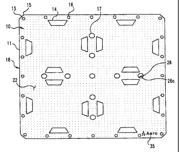
FIG. 1 is a top elevational view of a deck board according to one
embodiment of the present invention.
FIG. 2 is a side elevational view of the deck board depicted in FIG. 1.
FIG. 3 is a bottom elevational view of the deck board shown in FIGS.
1-2.
FIG. 4 is cross-sectional view of the deck board shown in FIG. 3, taken
along line A-A as viewed in the direction of the arrows.
FIG. 5 is a perspective view of a cargo trailer with installed deck
boards.
FIG. 6 is a perspective view of a deck board according to another
embodiment of the present invention.
FIG. 7 is a perspective view of the bottom face of the deck board
shown in FIG. 6.
FIG. 8 is an enlarged perspective partial view of the top face of the
deck board shown in FIGS. 6-7.
FIG.9 is an enlarged perspective partial view of the top face of a deck
board according to a further embodiment of the invention.
FIG. 10 is a cross-sectional view of one preferred embodiment of the
deck board shown in FIGS. 6-7 mounted on a truck load beam.
FIG. 11 is another cross-sectional view of the preferred embodiment of
the deck board shown in FIGS. 6-7 mounted on a truck load beam.
7
CA 02390272 2002-06-11
1810-0019
DESCRIPTION OF THE PREFERRED EMBODIMENTS
For the purposes of promoting an understanding of the
principles of the invention, reference will now be made to the embodiments
illustrated in the drawings and specific language will be used to describe the
same. It will nevertheless be understood that no limitation of the scope of
the
invention is thereby intended. The invention includes any alterations and
further modifications in the illustrated devices and described methods and
further applications of the principles of the invention which would normally
occur to one skilled in the art to which the invention relates.
The present invention relates to cargo handling structures, particularly
deck boards. More specifically, the invention concerns a plastic molded deck
board that forms a surface for supporting cargo on top of trailer load beams.
In accordance with one embodiment of the present invention, deck
board 10 is shown in FIG. 1. The deck board 10 can be formed as a single
piece of molded plastic, nylon, or similarly durable, lightweight material.
Standard molding techniques, such as rotational molding or blow molding, are
preferred methods of construction, though other techniques could be used.
The plastic composition produces a durable and lightweight deck board 10
that is readily distinguished from often misused and misplaced wood pallets.
Referring to FIGS. 1, 2, and 3, the deck board 10 comprises a
rectangular platform 11 having a top face 22, a bottom face Z3, and side
faces 18. In one embodiment, the platform 11 can define a hollow chamber
24 enclosed by the top face 22, the bottom face 23, and the side faces 18. In
a most preferred embodiment, the platform 11 is 4' x 4' x 1.25" (122 cm. X
122 cm. X 3.2 cm.) and the material is plastic with a wall thickness of
0.1875"
(0.5 cm.). As depicted in FIG. 5, using this preferred size, several deck
boards 10 can fit side-by-side in a conventional cargo trailer 32. The
preferred embodiment is also lightweight and can be easily handled by one
person. The deck board can be sized for accommodating other trailers,
various load beam 31 configurations, or different cargo requirements. For
8
,i~~ ~i t~
CA 02390272 2002-06-11
1810-0019
example, a 4' x 8' (122 cm. X 244 cm.) platform 11 could be constructed that
would give uninterrupted support of larger cargo within a standard hauling
trailer, and also reduce the number of deck boards 10 required for a given
application. Load beams 31 are available that can be easily reconfigured to
support various platform sizes.
At least one vent hole 25 can be defined in the molded platform 11,
preferably at side face 18, to provide pressure equalization between the
hollow chamber 24 and the ambient pressure. To increase resistance to
cracking and splitting, stress can be distributed by using a 0.125" (0.3 cm.)
radius at the edges 28 formed by features of the deck board 10.
The top face 22 is substantially flat to support cargo. Preferably, the
top face can include a plurality of small nodular protrusions 29 to increase
the
surface friction and reduce the likelihood of cargo slippage. The corners 13,
of the platform 11 can be modified to reduce the likelihood of damage to the
corners and likelihood of injury to persons handling the deck board 10. As
viewed from the top face 22 or bottom face 23, each corner formed by
adjacent side faces 18 can have a truncated or notched comer to replace the
otherwise 90° comer 13 with two 135° comers 15.
Referring to FIGS. 2 and 3, a plurality of raised ribs 12 are defined on
the bottom face 23 of the platform 11. The ribs 12 are oriented and
positioned in a predetermined pattern so as to define channels 19 at the
center lines of the bottom face 23 and shoulders 20 at the periphery. in one
embodiment, depicted in FIG. 3, the ribs are 0.75" (1.9 cm.) deep and extend
across a quadrant of the bottom face 23 at 45° to the side faces 18.
The
truncated rib ends 21 are located and angled to define the center channels 19
and shoulders 20 for receiving load beams 31. The channels 19a and 19b
are defined from the midpoint 25a and 25b of two side faces 18a and 18b, to
the midpoint 25c and 25d of the opposite side faces 18c and 18d, operating
to receive a supporting center load beam 33 on either axis of the bottom face
23. The shoulders 20 are of a predetermined width along the periphery of the
9
p,;,~:: p~ .I
CA 02390272 2002-06-11
1810-0019
bottom face 23 for receiving a supporting end load beam 34 along any two or
more side faces 18a, 18b, 18c, and 18d, preferably along the two sides
opposite the center load beams 33 as depicted in FIG. 5. In one embodiment
the center channels 19 are 3" (7.6 cm.) wide and the shoulders 20 are 2" (5.1
cm.) wide, each sized for receiving load beams 31 slightly under 3" (7.6 cm.)
wide.
The ribs 12 and load beams 31 cooperate to maintain the position of
the deck board 10. The ribs 12 abutting the load beams 31 inhibit sliding of
the deck board 10 on the load beams. In one load beam configuration,
depicted by FIG. 5, three parallel toad beams 31 support a single deck board
10, one received by a center channel 19 and the other two received by
opposite shoulders 20. Because the pattern of the channels 19 and
shoulders 20 remain the same as viewed from any side face 18, the
supporting center load beam 33 can be received by either channel 19a or
19b, and the end load beams 34 by either shoulders 20a and 20c or 20b and
20d. Thus, orientation, other than top face 22 versus bottom face 23, is
irrelevant when loading or unloading the deck board 10.
The platform 11 can further define a plurality of bores 17 within the
channels 19 and extending therethrough. Each bore 17 forms a walled
interior cylinder 26 that functions to increase the rigidity of the platform
11
where the weight of the supported cargo is transferred from the deck board
to the center load beam 33. In one embodiment four 2" (5.1 cm.)diameter
bores are defined within each channel 19a and 19b and one bore is defined
at the intersection of channels 19a and 19b. In one feature, a thin web 26A
can extend across the interior wall 26 of any of the bores 17. The web 26A
serves to initially close the opening but can be punched out as required. For
instance, the web 26A can be removed if it is desired to provide drainage
through the deck board, or to use the bore as a tie down location. Even with
the web in place, the bore 17 retains its beneficial structural capabilities.
a ~~ a : v. i n
CA 02390272 2002-06-11
1810-0019
The platform 11 can further define a plurality of retaining holes 16
within the shoulders 20 and extending therethrough. The holes 16 can
receive fasteners, ropes, or other devices to secure the deck board 10 to the
load beams 31 or to an adjacent deck board 10. In one embodiment, the
retaining holes are 1" (2.5 cm.) diameter.
The platform 11 can further define a plurality of openings 14 extending
therethrough and having a predetermined shape suitable for functioning as
handholds. In addition to functioning as handholds, the openings can receive
cargo straps. The handhold openings 14 are preferably defined through the
platform 11 in areas outside of the shoulders 20, channels 19, and raised ribs
12. The handhold openings 14 can be positioned individually or in opposing
pairs. In one embodiment the handhold openings 14 are positioned in pairs
spaced approximately shoulder width apart to accommodate easy handling.
When viewed from each side 18a, 18b, 18c, and 18d, a pair of openings 14 is
located near the shoulder 20 and along the center channel 19.
In anther embodiment as depicted in FIGS. 6-9, a deck board 50
comprises a plastic platform 51 having a top face 52 for supporting cargo, a
plurality of side faces 54 extending along a perimeter P of the platform 51,
and a bottom face 53 at the underside of the platform 51.
As shown in FIG. 7, the bottom face 53 defines a plurality of side walls
55A, 55B, 55C, 55D extending from the plurality of side faces 54 along
corresponding edges 49A, 49B, 49C, 49D of the platform 51. The platform
51 can be positioned on the load beams of a cargo trailer such that at least
two of the plurality of edges 49A, 49B, 49C, 49D rest on at last two end load
beams 72, while a center portion 48 of the platform 51 can rest of a center
load beam 71 (see FIGS. 10 and 11 ).
The plurality of side walls 55A, 558, 55C, 55D preferably includes a
plurality of inner side walls 61 and a plurality of outer side walls 62,
spaced
apart to provide reinforcement for the platform 51. The inner side walls 61
11
L.;. I, w d~ I II
CA 02390272 2002-06-11
1810-0019
are preferably offset from the outer side walls 62 by a half of the width of
the
end load beam 72. In a specific embodiment this offset is about 1" (2.5 cm.).
The bottom face 53 further may define four angled cross walls 56A,
56B, 56E, 56F. Each of the angled cross walls has a first end disposed near
the center 48 of the platform and a second end abutting one of the side walls
55A, 55B, 55C, 55D are a right angle. The first end of each of the angled
cross walls 56A, 56B, 56E, 56F has an extended height, which gradually
decreases towards the second end. The height of the second end of the
walls 56A, 56B, 56E, 56F is substantially flush with the side walls 55A, 55C.
The bottom face 53 further includes a first channel 57A and a second channel
57C. The first channel 57A is disposed between two angled cross walls 56E,
56F and extends from near the center 48 to an opposite edge 49C. Similarly,
the second channel 57C is disposed between two angled cross walls 56E,
56F, and extends from near the center 48 to an opposite edge 49C. The first
channel 57A and the second channel 57C linearly line up to form a first
platform channel 75 for receiving a center load beam 71 of a cargo trailer
(see
FIG. 10).
The bottom face 53 may further include 57 a third channel 57B, and a
fourth channel 57D. The third channel 57B is disposed between two angled
cross walls 56C, 56D, and extends from near the center 48 to another edge
49B. Similarly, the fourth channel 57D is disposed between two angled cross
walls 56G, 56H, and extends from near the center 48 to another opposite
edge 49D. The third channel 57B and the fourth channel 57D linearly line up
to form a second platform channel 76 extending perpendicularly to the first
platform channel 75.
Each of the first platform channel 75 and the second platform channel
76 defines a plurality of support bars 58 having substantially the same height
as that of the side walls 55A-55D. As shown in FIG. 10, when the deck board
50 is positioned on the load beams of the cargo trailer, the first platform
channel 75 extends along the center load beam 71 such that the support bars
12
:~'ii I,.:
CA 02390272 2002-06-11
1810-0019
58 and the side walls (not shown) rest on a top side 77 of the center load
beam 71. The angled cross walls 56A and 56B drape along two vertical sides
78 of the center load beam 71. In the dame instance, as shown in FIG. 11,
the inner since walls 61 and the outer side walls 62 rest on a top surface 79
of
the end load beam T2.
Further in this embodiment, the bottom face 53 of the platform 51
defines a plurality of cross bars 60A-60H extending between the side walls
55A-55D. Preferably the cross bars 60A-60H define a honeycomb pattern
with individual cells 69 for optimum strength.
As shown in FIGS. 6 and 8, the top face 52 can define a plurality of
nodular protrusions 63A, 63B and 63C operable to increase surface friction to
reduce slippage of cargo on the deck board. Preferably, the nodular
protrusions 63A, 63B and 63C have a substantially conical shape or a
pyramid shape to increase wear resistance. Moreover, the protrusions can
have variable heights as demonstrated in FIG.B. When the cargo is placed
on the top face 52, the nodular protrusions 63A, 63B and 63C provide surface
friction to reduce slippage and sliding of the cargo during its transport. The
variable height protrusions, wear down at different rates, and thus prolong
the
life of the entire array of protrusions. Most preferably, the modular
protrusions 63A, 63B and 63C can be molded on the plastic platform 51.
Referring to FIG. 9, the top face 52 can also include a plurality of
rubber stoppers 73 mounted along the surface edges 47 of the top face 52. A
top portion 74 of each rubber stopper 73 protrudes slightly from the top face
52 to prevent the cargo from sliding off the deck board 50. A lower portion of
the stopper can fit within an opening in the board, such as opening 59. The
rubber stoppers 73 are configured to provide surface fiction that helped
slippage between stacked deck boards.
Returning to FIGS. 6, 7, and 9, the platform 51 further defines a
plurality of openings 59 extending between the top face and the bottom face
therethrough, so that the weight of the platform 51 is reduced. Two or more
13
I il
CA 02390272 2002-06-11
1810-0019
of the openings 59 preferably have a predetermined shape suitable for
functioning as handholds 68. The openings 59 may be positioned for
receiving cargo fasteners (not shown). The cargo fasteners can be rope, a
strap, or a belt for securing the cargo to the deck boards 50.
Similar to the platform 11 in the embodiment shown in FIGS. 1-4, the
platform 51 further includes a plurality of bores 64 (see FIG. 6) extending at
least partially between the top face 52 and the bottom face 53 therethrough.
The bores 64 are disposed adjacent to the perimeter P of the platform 51,
and preferably along the first platform channel 75 and the second platform
channel 76. The bores 64 are capable of receiving support posts (not shown)
or receiving fasteners (not shown) to secure the platform 51 to a center load
beam or an end load beam. In addition, the bores 64 may receive fasteners
(not shown) for retaining a plurality of platforms together. Each of the bores
64 defines an interior cylindrical wall 65, which may include a web 66
extending across the interior cylindrical wall 65 for supporting the support
post. In addition, the inner side walls 61 may span across the bores 64 to
provide further support.
Furthermore, in the preferred embodiment shown in FIG. 6, the top
face 52 defines recessed slots 70A-70H positioned for receiving the first end
of the angled cross walls 56A-56H of another deck board. When two or more
deck boards are being stored, they can be stacked on top of each other such
that the angled cross walls of the top deck board fit into the recessed slots
of
the bottom deck board. This feature allows several deck boards to be sturdily
stacked together with little risk of the deck boards slipping off the stack.
In a further feature of the most preferred embodiment, an identifying
means can be incorporated into the deck board 10 by molding in a design 35
specifying one of use or ownership. Because the molded design cannot be
readily removed, the deck board will not be easily misidentified or stolen.
Alternatively, at least one depression 67 (see FIG. 6) can be molded into the
top face 52 of the platform 51 to receive an identification label (not shown).
14
i, i n
CA 02390272 2002-06-11
1810-0019
The depression 67 keeps the identification label protected below the surface
of the deck board.
In addition, since the invention contemplates a molded plastic product,
the plastic can be injected with a predetermined color during the molding
process. Since the color is in the plastic material itself, it cannot fade or
chip
and does not require re-painting as would be necessary for a wooden pallet.
The color of the deck board can be used to readily identify boards belonging
to a particular transport company, whether to facilitate the return of the
deck
boards to the owner or to identify a stolen board.
While the invention has been illustrated and described in detail in the
drawings and foregoing description, the same is to be considered as
illustrative and not restrictive in character. It should be understood that
only
the preferred embodiments have been shown and described and that all
changes and modifications that come within the spirit of the invention are
desired to be protected.