Note: Descriptions are shown in the official language in which they were submitted.
CA 02390284 2007-08-08
77223-12
Apparatus and Method for Preparing Microparticles
Background of tlze Invention
Field of tlie Invention
The present invention relates to preparation of microparticles. More
particularly,
the present invention relates to a method and an apparatus for preparing
microparticles
having a more controlled and symmetrical particle size distribution.
Related Art
A variety of methods is known by which compounds can be encapsulated in the
form of microparticles. It is particularly advantageous to encapsulate a
biologically active
or pharmaceutically active agent within a biocompatible, biodegradable wall
forming
material (e.g., a polymer) to provide sustained or delayed release of drugs or
other active
agents. In these methods, the material to be encapsulated (drugs or other
active agents) is
generally dissolved, dispersed, or emulsified, using stirrers, agitators, or
other dynamic
mixing techniques, in a solvent containing the wall forming material. Solvent
is then
removed from the microparticles and thereafter the microparticle product is
obtained.
Development of a microencapsulation process suitable for commercial scale
production typically requires scaling up, by multiple factors, a laboratory
scale process
and/or a pilot scale process. The scaled-up process will almost always require
larger
piping and higher flow rates, particularly when the scale factor is very large
or if it is
desired or necessary to keep process transfer times similar to the smaller
scale processes.
Scale-up into new, larger equipment is often unpredictable and achieved in
large measure
through trial and error. However, the economic costs of large-scale trial and
error
experiments can be prohibitive.
-1-
CA 02390284 2002-05-07
WO 01/34113 PCT/USOO/41842
One approach to aiding the scale-up process is to use a static mixer to form
an
emulsion, as disclosed in U.S. Patent No. 5,654,008. In the method disclosed
in U.S.
Patent No. 5,654,008, a first phase, comprising the active agent and the
polymer, and a
second phase are pumped through a static mixer into a quench liquid to form
microparticles containing the active agent. The use of a static mixer to form
the emulsion
tends to make the scale-up more predictable and reliable than the scale-up of
other
dynamic-mixing processes for making microparticles. However, numerous trials
and
experiments are still required to completely and accurately scale-up, such as
to commercial
scale or by a factor of 20 or more, a process such as the one disclosed in
U.S. Patent No.
5,654,008.
For a commercial scale process, it is particularly important to control the
distribution of the size of the microparticles to minimize yield losses. For
example,
microparticles, particularly controlled release microparticles containing an
active agent or
other type of substance to be released, can range in size of from about 25 m
to about 250
m in diameter. For a particular commercial product, the useful or desired
microparticle
size range can be in the range of, for example, 25-150 m. Even in an
efficient
commercial production process, some percentage of the microparticles produced
will be
larger than the upper size limit, and some percentage of the microparticles
produced will be
smaller than the lower size limit, resulting in yield losses. Typically, the
more narrow or
tighter the desired microparticle size range, the larger the yield losses that
result. These
yield losses could be avoided or minimized if a more narrow microparticle size
distribution
could be achieved. Narrowing the microparticle size distribution eliminates or
significantly
reduces the losses resulting from microparticles that fall outside of the
desired
microparticle size range.
Thus, there is a need in the art for an improved method and apparatus for
preparing
microparticles. There is a particular need in the art for an improved process
that can
control particle size distribution, and achieve a more narrow particle size
distribution.
There is a further need in the art for an improved process that can be more
quickly,
reliably, and accurately scaled-up from a laboratory or pilot scale to a
commercial scale.
The present invention, the description of which is fully set forth below,
solves the need in
the art for such improved methods and apparatus.
-2-
CA 02390284 2002-05-07
WO 01/34113 PCT/USOO/41842
Summary of the Invention
The present invention relates to an apparatus and method for preparing
microparticles. In one aspect of the invention, a method of preparing
microparticles is
provided. The method comprises:
preparing a first phase, the first phase comprising an active agent and a
polymer;
preparing a second phase;
preparing a quench liquid;
pumping the first phase and the second phase through a first static mixer to
form an
emulsion; and
flowing the emulsion through a manifold that includes a plurality of static
mixers
into the quench liquid whereby droplets of the emulsion form microparticles.
In a further aspect of the present invention, another method for preparing
microparticles is provided. The method comprises:
preparing a first phase, the first phase comprising an active agent and a
polymer;
preparing a second phase;
preparing a quench liquid;
combining the first phase and the second phase in a first static mixer to form
an
emulsion, the emulsion forming an outflow of the first static mixer;
dividing the outflow of the first static mixer to form at least two flow
streams;
flowing each of the at least two flow streams through a separate second static
mixer; and
combining the at least two flow streams with the quench liquid whereby
droplets of
the emulsion form microparticles.
In a further aspect of the present invention, a method for controlling
particle size
distribution of microparticles is provided. The method comprises:
preparing a first phase, the first phase comprising an active agent and a
polymer;
preparing a second phase;
preparing a quench liquid;
pumping the first phase and the second phase through a static mixing assembly
to
form an emulsion;
flowing the emulsion into the quench liquid whereby droplets of the emulsion
form
microparticles; and
-3-
CA 02390284 2002-05-07
WO 01/34113 PCT/US00/41842
adjusting a residence time of the emulsion in the static mixing assembly to
obtain a
predetermined particle size distribution of the resulting microparticles,
wherein the
residence time is equal to a length of the static mixing assembly divided by
an average
velocity of the emulsion through the static mixing assembly.
In yet a further aspect of the present invention, a microencapsulated active
agent
prepared by a method for preparing microparticles is provided. Such a method
comprises:
preparing a first phase, the first phase comprising an active agent and a
polymer;
preparing a second phase;
preparing a quench liquid;
pumping the first phase and the second phase through a first static mixer to
form an
emulsion; and
flowing the emulsion through a manifold that includes a plurality of static
mixers
into the quench liquid whereby droplets of the emulsion form microparticles.
In yet a further aspect of the present invention, a microencapsulated active
agent
prepared by another method for preparing microparticles is provided. Such a
method
comprises:
preparing a first phase, the first phase comprising an active agent and a
polymer;
preparing a second phase;
preparing a quench liquid;
combining the first phase and the second phase in a first static mixer to form
an
emulsion, the emulsion forming an outflow of the first static mixer;
dividing the outflow of the first static mixer to form at least two
substantially
identical flow streams;
flowing each of the at least two substantially identical flow streams through
a
separate second static mixer; and
combining the least two substantially identical flow streams with the quench
liquid
whereby droplets of the emulsion form microparticles.
In still a further aspect of the present invention, a system for preparing
microparticles is provided. The system includes a first and second pump, and a
first static
mixer in fluid communication with each of the pumps. One of the pumps is
configured to
pump an organic phase into the first static mixer. One of the pumps is
configured to pump
a continuous phase into the first static mixer. A manifold, comprising a
plurality of static
mixers, is in fluid communication with the first static mixer. An extraction
vessel is in
-4-
CA 02390284 2002-05-07
WO 01/34113 PCT/US00/41842
fluid communication with the manifold. The outflow of the first static mixer
flows through
the manifold into the extraction vessel. The plurality of static mixers in the
manifold can
be configured in parallel or in series.
Features and Advantages
It is a feature of the present invention that it can be used to prepare
microparticles,
including microparticles containing an active agent.
A significant advantage of the present invention is that it provides a method
for
controlling particle size distribution. By controlling particle size
distribution, yield losses,
resulting from microparticles that fall outside of a desired microparticle
size range, can be
substantially reduced or eliminated. This makes the present invention
particularly useful
for commercial products.
The present invention also advantageously allows for use of a more narrow or
tighter target microparticle size range than in conventional processes.
Narrowing the limit
for the microparticle size range typically results in larger yield losses.
These yield losses
can be avoided or minimized by achieving a more narrow microparticle size
distribution
through the process of the present invention.
The present invention provides a method and apparatus that are particularly
advantageous for scale-up. The parallel path manifold of the present invention
allows for
capacity increases from an established (single path) system without full-scale
trial and
error experiments in new and different equipment. The total flow rate can be
increased
from the single path system based upon the number of flow streams in the
manifold.
Brief Description of the Figures
The present invention is described with reference to the accompanying
drawings.
In the drawings, like reference numbers indicate identical or functionally
similar elements.
FIG. 1 illustrates flow through a static mixer;
FIG. 2 shows a static mixer suitable for use with the present invention;
FIGS. 3A-3C show various types or designs of static mixing elements;
FIG. 4 depicts a graph of mass median diameter (microns) of microparticle size
distribution as a function of average emulsion velocity (cm/min);
-5-
CA 02390284 2007-08-08
77223-12
FIG. 5 depicts a graph of width of microparticle size distribution, as
expressed by
CoVR,, for various static mixers as a function of emulsion residence time
(sec) in the static
mixer;
FIG. 6 depicts a graph of skewness of microparticle size distribution for
various
static mixers as a function of emulsion residence time (sec) in the static
mixer; and
FIG. 7 shows an exemplary embodiment of an equipment configuration for
preparing microparticles in accordance with the present invention.
Detailed Description of the Preferred Embodiments
Overview
The present invention provides an improved method and apparatus for preparing
microparticles. Maximum yield within a desired microparticle size range is an
important
aspect of any process or method for preparing microparticles. The size of the
resulting
microparticles is primarily controlled during the emulsification step of the
process of the
present invention. As will be explained in more detail below, the
emulsification step uses
an in-line motionless or static mixer to create an emulsion from a first
phase, comprising a
polymer and a drug or other active agent, and a second phase, preferably an
aqueous
solution. The inventors of the present invention have unexpectedly found that
the most
dominant influential characteristic controlling the dispersity of
microparticle size is the
residence time of the emulsion in the static mixer before the emulsion is
introduced to a
2o quench or solvent-extraction liquid. Increased residence time in the
emulsion-forming
static mixer decreases polydispersity, and results in a more symmetrical
particle size
distribution.
The methods of the present invention use a static mixer to combine a first
phase,
comprising an active agent and a polymer, with a second phase to form an
emulsion. The
static mixer in which the first and second phases are combined to form the
emulsion may
be referred to herein as a "preblending static mixer". A process for forming
an emulsion
using a static mixer is described, for example, in U.S Patent
No. 5,654,008. The phase comprising the active agent and the
polymer may be referred to herein as the "organic phase". The other phase may
be referred
to herein as the "continuous phase".
The emulsion flowing out of the preblending static mixer flows through a
manifold
containing a plurality of static mixers into a quench liquid whereby droplets
of the
-6-
CA 02390284 2002-05-07
WO 01/34113 PCTIUSOO/41842
emulsion form microparticles. Alternatively, the outflow of the preblending
static mixer is
divided to form at least two flow streams. Each of the flow streams then flows
through
another separate static mixer. The flow streams are recombined downstream, and
combined with the quench liquid whereby droplets of the emulsion form
microparticles.
In a particularly preferred embodiment, the diameter of the preblending static
mixer
is greater than the diameter of the static mixers in the manifold, i.e.,
greater than the
diameter of the static mixers through which the divided flow streams flow.
When using a
static mixer to form an emulsion, a variety of factors determine emulsion
droplet size.
Emulsion droplet size determines the size of the resulting microparticles.
These factors
lo include the density and viscosity of the various solutions or phases to be
mixed, volume
ratio of the phases, interfacial tension between the phases, static mixer
parameters (conduit
diameter; length of mixing elements; number of mixing elements), and fluid
velocity
through the static mixer. The primary controlling variable is fluid velocity.
Droplet size
decreases as fluid velocity increases. Similarly, droplet size increases as
fluid velocity
(and pressure drop) decreases. Accordingly, the preblending static mixer is
preferably
larger in diameter than the static mixers in the manifold in order to handle
the total flow
from the feed streams (organic phase and continuous phase) at a lower velocity
than the
smaller diameter static mixers in the manifold.
In the present invention, a preblending static mixer is used to combine the
organic
phase and the aqueous phase to form the emulsion. In one embodiment, the
emulsion is
divided into a plurality of flow streams for flow through the manifold. The
use of the
preblending static mixer prior to the manifold is particularly advantageous
because the
organic phase and the aqueous phase are not immediately miscible or
homogeneous,
making the division of the combined flow stream problematic. For multiphase
(e.g.,
oil/water) streams, the use of the manifold without the preblending static
mixer could result
in different compositions in each static mixer in the manifold. Because the
combined
organic and aqueous phases is not homogeneous, it would not divide evenly in
conventional piping.
The manifold configuration of the present invention is particularly
advantageous
for scale-up. The parallel path manifold of the smaller diameter static mixers
allows for
capacity increases from an established (single path) system without full-scale
trial and
error experiments in new and different equipment. The total flow rate can be
increased
from the single path system based upon the number of flow streams in the
manifold.
-7-
CA 02390284 2002-05-07
WO 01/34113 PCT/US00/41842
The present invention advantageously provides a method for controlling
particle
size distribution of microparticles. A first phase, comprising an active agent
and a
polymer, and a second phase are pumped through a static mixing assembly to
form an
emulsion. The emulsion flows into a quench liquid, whereby droplets of the
emulsion
form microparticles. By adjusting a residence time of the emulsion in the
static mixing
assembly, a predetermined particle size distribution of the resulting
microparticles can be
obtained. The residence time is equal to a length of the static mixing
assembly divided by
an average velocity of the emulsion through the static mixing assembly. The
particle size
distribution can be narrowed by increasing the residence time. The particle
size
distribution can be broadened by decreasing the residence time. The residence
time is
preferably adjusted by changing the length of the static mixing assembly.
To ensure clarity of the description that follows, the following definitions
are
provided. By "microparticles" or "microspheres" is meant solid particles that
contain an
active agent or other substance dispersed or dissolved within a polymer that
serves as a
matrix or binder of the particle. The polymer is preferably biodegradable and
biocompatible. By "biodegradable" is meant a material that should degrade by
bodily
processes to products readily disposable by the body and should not accumulate
in the
body. The products of the biodegradation should also be biocompatible with the
body. By
"biocompatible" is meant not toxic to the body, is pharmaceutically
acceptable, is not
carcinogenic, and does not significantly induce inflammation in body tissues.
As used
herein, "body" preferably refers to the human body, but it should be
understood that body
can also refer to a non-human animal body. By "weight %" or "% by weight" is
meant
parts by weight per total weight of microparticle. For example, 10 wt.% active
agent
would mean 10 parts active agent by weight and 90 parts polymer by weight.
Unless
otherwise indicated to the contrary, percentages (%) reported herein are by
weight. By
"controlled release microparticle" or "sustained release microparticle" is
meant a
microparticle from which an active agent or other type of substance is
released as a
function of time. By "mass median diameter" is meant the diameter at which
half of the
distribution (volume percent) has a larger diameter and half has a smaller
diameter.
-8-
CA 02390284 2007-08-08
f =
77223-12
Method and Examples
The following examples are provided to explain the invention, and to describe
the
materials and methods used in carrying out the invention. The examples are not
intended
to limit the invention in any manner.
Example 1- Static Mixer Tests
A test program was conducted using a variety of static mixers. A static or
motionless mixer consists of a conduit or tube in which is received a number
of static
mixing elements. Static mixers provide uniform mixing in a relatively short
length of
conduit, and in a relatively short period of time. With static mixers, the
fluid moves
through the mixer, rather than some part of the mixer, such as a blade, moving
through the
fluid. Flow through one type of static mixer is illustrated in Figure 1. A
pump (not shown)
introduces a stream of one or more fluids into a static mixer 10, as shown
generally at 1.
The stream is split and forced to opposite outside walls, as shown generally
at 2. A vortex
is created axial to the centerline of static mixer 10, as shown generally at
3. The vortex is
sheared and the process recurs, but with the opposite rotation, as shown
generally at 4.
The clockwise/counterclockwise motion ensures a homogeneous product.
One example of a static mixer is shown in Figure 2. Static mixer 10 includes a
number of stationary or static mixing elements 14 arranged in a series within
a conduit or
pipe 12. The number of static mixing elements can range from 4 to 32 or more.
Conduit
12 is circular in cross-section and open at opposite ends 18 and 20 for
introducing and
withdrawing fluids. Mixing element 14 comprises segments 142. Each segment 142
consists of a plurality of generally flat plates or vanes 144. The two
substantially identical
segments 142 are preferably axially staggered with respect to each other. A
static mixer as
shown in Figure 2 is more fully described in U.S. Patent No. 4,511,258.
Each of the static mixers tested displayed characteristic differences in
design,
length, diameter, and number of elements per length. A key aspect to the
design of a static
mixer is the geometry of the static mixing elements. The eight static mixers
tested used
three different types of static mixing elements: scissors elements; helical
elements; and
layered elements. A scissors mixing element, shown in Figure 3A, has two rows
of baffles
affixed perpendicular to each other, creating the impression of a pair of
opened scissors. A
helical mixing element, shown in Figure 3B, uses a 180 helical plane with a
90 offset and
-9-
CA 02390284 2002-05-07
WO 01/34113 PCTIUSOO/41842
alternating direction of sequential elements. A layered element, shown in
Figure 3C, uses
corrugated sheets welded together to form open channels.
The characteristics of the eight static mixers tested are shown below in Table
1.
The mixers ranged in size from 2'/2 inches in length with 5 mixing elements to
93/4 inches
in length with 24 mixing elements. By arranging identical static mixers in
series, the
length and the number of mixing elements was increased; however, the number of
mixing
elements per unit length remained constant. The diameter of the static mixers
tested
ranged from 1/4 inch to V2 inch.
Characteristics of the Test Mixers
# of Element
Mixer # Diameter Length Elements Design Material Manufacturer
1 '/4" 6" 24 Helical Plastic Cole Palmer
2 '/4" 9'/<" 24 Helical Stainless TAH
Steel
3 3/8" 4'/4" 12 Helical Plastic Cole Palmer
4 3/8" 9" 12 Helical Stainless Kenics
Steel
5 3/8" 2'h" 5 Layered Stainless Koch
Steel
6 '/z" 5" 12 Helical Plastic TAH
7 'h" 6" 12 Helical Plastic Cole Palmer
8 5/16" 2 7/8" 12 Scissors Plastic Omega
Table 1
One-hundred gram batches of 40% theoretically loaded risperidone
microparticles
were used to test the static mixers. A 16.7% polymer solution was prepared by
dissolving
60 grams of MEDISORB 7525 DL polymer (Alkermes, Inc., Blue Ash, Ohio) in
ethyl
acetate. A 28.6% drug solution was prepared by dissolving 40 grams of
risperidone base
(Janssen Pharmaceutica, Beerse, Belgium) in benzyl alcohol. The organic phase
was
prepared by mixing the drug solution into the polymer solution. The continuous
or
aqueous phase was a 1% polyvinyl alcohol (PVA) solution containing 6.5% ethyl
acetate.
The temperature of the organic and aqueous phases was 25 C. The ratio of the
aqueous
phase to the organic phase was 5:1. The quench liquid or extraction solution
was an
aqueous solution containing 2.5% ethyl acetate at 25 C. The ratio of the
volume of
extraction solution to batch size was 0.25 liters/gram.
The 100-gram batches were produced by forming an oil-in-water emulsion, and
then extracting the solvent from the emulsion droplet to form a hardened
polymer/drug
microparticle. Two calibrated micropumps fed the static mixer under test, one
micropump
-10-
CA 02390284 2002-05-07
WO 01/34113 PCTIUSOO/41842
for the organic phase and one micropump for the aqueous phase. The micropumps
were
calibrated by monitoring total volume pumped over a timed period prior to the
batch being
run. A "Y" connection upstream of the static mixer under test was used to
introduce the
organic phase into the aqueous phase.
The static mixer under test discharged the resulting emulsion directly into an
agitated extraction solution. The emulsion remained in the extraction solution
for fifteen
minutes to harden into microparticles. A sample of the resulting
microparticles was tested
using a Coulter LS230 Small Module particle size analyzer to determine
particle size
distribution. The flow rates were adjusted to target a mass median diameter of
between
lo about 30 m and 90 m. The experimental results for the eight static mixers
tested is
shown below in Table 2.
Summary of Experimental Results
Mixer Process Conditions Particle Data
Cal.
otal Cal. Residence Skew-
No. Geometry Diameter Elements Length Flow Velocity Time 4edian @ 84% @ 16%
CoV,,, Mean CoV~ ness
(in) (#) (in) (ml/min) (cm/min) (see) um) (um) (um) (um)
I Helical 0.250 24 6.00 71 3068 0.298 4.60 43.88 6.07 1.54 25.45 0.666 0.259
1 Helical 0.250 24 6.00 64 1467 0.623 54.56 92.01 18.83 1.34 55.85 0.606 0.260
1 Helical 0.250 24 6.00 329 1039 0.880 87.76 159.10 33.30 1.43 97.33 0.667
0.846
2 Helical 0.250 24 9.75 60 3033 0.490 57.28 120.80 16.65 1.82 67.37 0.748
0.751
3 Helical 0.375 12 4.75 1140 1600 0.452 3.20 88.64 13.59 1.74 50.01 0.723
0.737
3 Helical 0.375 12 4.75 1213 1703 0.425 7.93 89.66 18.40 1.49 53.2 0.627 0.590
3 Helical 0.375 12 4.75 1215 1706 0.424 7.13 90.58 15.14 1.60 52.11 0.677
0.532
3 Helical 0.375 60 23.50 1133 1591 2.251 53.25 85.31 18.70 1.25 52.8 0.577
0.127
3 Helical 0.375 144 57.00 1036 1455 5.971 54.11 90.86 19.96 1.31 55.71 0.593
0.326
4 Helical 0.375 12 9.00 2792 3920 0.350 70.62 150.60 24.41 1.79 85.34 0.745
0.911
4 Helical 0.375 12 9.00 3527 4952 0.277 53.28 105.90 21.45 1.59 61.93 0.654
0.754
4 Helical 0.375 12 9.00 3703 5199 0.264 5.40 98.83 15.00 1.85 55.7 0.781 1.075
4 Helical 0.375 12 9.00 3487 4896 0.280 2.11 113.70 17.34 1.85 64.37 0.789
1.150
4 Helical 0.375 36 27.00 2888 4055 1.015 81.66 131.20 31.68 1.22 82.36 0.556
0.226
5 Layered 0.375 5 2.50 1166 1637 0.233 109.60 248.20 29.14 2.00 133.5 0.769
0.682
5 Layered 0.375 5 2.50 423 3402 0.112 9.37 58.21 6.71 1.75 32.89 0.743 0.730
6 Helical 0.500 12 5.00 2764 2183 0.349 2.25 82.85 13.19 1.65 47.27 0.693
0.577
7 Helical 0.500 12 6.00 3929 3103 0.295 1.51 43.89 4.75 1.82 24.22 0.731 0.546
7 Helical 0.500 12 6.00 507 2770 0.330 9.67 57.92 7.59 1.70 32.68 0.705 0.499
7 Helical 0.500 12 6.00 684 2120 0.431 0.03 71.89 12.50 1.48 42.05 0.638 0.283
7 Helical 0.500 36 18.00 779 2195 1.250 18.37 83.19 15.68 1.40 49.52 0.614
0.189
8 Scissors 0.313 12 2.88 09 1838 0.238 3.66 48.68 4.88 1.85 26.75 0.742 0.579
8 Scissors 0.313 12 2.88 620 1254 0.350 8.77 104.90 20.11 1.44 62.83 0.650
0.574
Table 2
-11-
CA 02390284 2002-05-07
WO 01/34113 PCT/USOO/41842
The average emulsion velocity and residence time through a static mixer can be
calculated from the flow rate into the static mixer and the length and
diameter of the static
mixer as follows:
(1) Average Velocity = flow rate/cross-sectional area of empty static mixer
(2) Residence Time = length of static mixer/Average Velocity
To characterize the particle size distribution, these parameters were
measured:
median, coefficient of variation of the median and skewness. The coefficient
of variation
of the median (CoVrõ) was used to characterize the span of the distribution.
(3) CoV,,, = (diameter of 0 at 84% - diameter of 6 at 16%)
MMD
As the CoV~õ approached zero, the distribution became more monodispered.
The symmetry of the distribution was determined using the skewness
coefficient. The
Coulter analyzer's method of determining skewness is as follows:
Skewness = IhLX, -x~
SD3 Enc
nr =# of particles in c'th channel x,= mean volume in the c'th channel
Xa= arithmetic mean of the distribution SD = standard deviation of the
distribution
As the distribution became more symmetrical, the skewness approached zero. For
right-skewed distributions (the particle size of the mode is less than the
mean) the
coefficient is positive; for left-skewed, the coefficient is negative.
Figure 4 shows the effect of the average emulsion velocity (cm/min) on the
mass
median diameter (MMD, microns) of the size distribution for the various static
mixers
under test. As shown in Figure 4, the MMD data for the plastic helical design
mixer
indicate a consistent well behaved inverse relationship between MMD and
average
velocity, independent of mixer diameter, length, and number of elements per
length. The
layered stainless steel (SS) mixer and the plastic scissors mixer also
demonstrated an
inverse relationship between MMD and average velocity. Figure 4 shows MMD data
for a
helical stainless steel (SS) mixer used to produce microparticles at the one
kilogram scale,
in a manner analogous to that described above for the 100 gram scale. The
inverse
relationship between MMD and average velocity was not readily apparent from
the
experimental data obtained with the stainless steel helical mixer at the one
kilogram scale.
Notably, this static mixer had the fewest elements per length (1.33 elements
per inch) of all
the static mixers tested.
-12-
CA 02390284 2002-05-07
WO 01/34113 PCT/US00/41842
Figure 5 shows the effect of emulsion residence time (sec) in the static mixer
on the
width of the microparticle size distribution (CoV,,,) using the various static
mixers under
test. An increase in residence time of the emulsion flowing through the static
mixer causes
a decrease in the width of the microparticle size distribution, until a
minimum is reached.
The data at extremely low residence times (less than one second) have high
variability, but
consistently show an increase in the width of the particle size distribution
as the residence
time decreases below one second.
Figure 6 shows the effect of emulsion residence time (sec) in the static mixer
on the
skewness of the microparticle size distribution. As shown in Figure 6, as
residence time
1o increased, the skewness of the microparticle size distribution decreased.
All of the
distributions were right-skewed.
Experiments were also performed at the one kilogram scale, in a manner
analogous
to that described above for the 100 gram scale. However, for the one kilogram
experiments, the number of static mixers was varied, using one, two, four, and
eight static
mixers arranged in series. The results of the one kilogram scale experiments
are shown
below in Table 3.
TABLE 3
Cal.
# of Flow Cal. Residence @ 25-125 25-150
Batch # Mixers Rate Velocity Time Median @84% @16% CoV,,, @25un @ 125uni 150un
yield* yield*
(ml/min) (cm/min) (sec) (um) (um) (um) % % % % %
1 kg-0210-7 1 3060 4297 0.319 74.85 135.1 24.98 1.47 17.94 78.31 88.85 60.37
70.91
-0218-7 1 3050 4283 0.320 79.95 135.4 29.85 1.32 N/R N/R N/R N/R N/R
-0319-7 1 3050 4283 0.320 70.57 141 26.27 1.63 N/R N/R N/R N/R N/R
-0325-7 1 3000 4212 0.326 71.51 122.3 24.95 1.36 14.96 77.11 85.88 62.15 70.92
-0506-7 2 3560 4999 0.549 67.4 113.1 22.38 1.35 N/R N/R N/R N/R N/R
-0708-7 4 3260 3325 1.650 59.38 97.22 24.99 1.22 N/R N/R N/R N/R N/R
-0908-7 8 3140 3202 3.426 70.73 102.6 30.39 1.02 12.3 96.69 99.86 84.39 87.56
-1014-7 8 3030 3090 3.551 80.57 121 30.37 1.12 13 86.3 95.96 73.3 82.96
Average 1 3040 4268 0.321 74.22 133.5 26.51 1.44 16.45 77.71 87.37 61.26 70.92
Std. dev. 27 38 0.003 4.24 7.9 2.31 0.14 2.11 0.85 2.10 1.26 0.01
Average 8 3085 3146 3.489 75.65 111.80 30.38 1.07 12.65 91.50 97.91 78.85
85.26
Std. dev. 78 79 0.088 6.96 13.01 0.01 0.07 0.49 7.35 2.76 7.84 3.25
* Theoretical yield based on the particle size analysis
Consistent with the 100 gram scale experiments, the results in Table 3 show
that
the width of the distribution of the microparticle size decreases with
increasing residence
time of the emulsion in the series of static mixers. As shown in Table 3, the
average
residence time for one static mixer was 0.321 sec, resulting in a CoV,T, of
1.44. Increasing
the average residence time to 3.489 sec through the use of eight mixers,
decreased the
-13-
CA 02390284 2002-05-07
WO 01/34113 PCT/US00/41842
CoVto 1.07. The longer average residence time also increased the average yield
in a
desired microparticle size range of 25-125 m by 28.71%, and in a desired
microparticle
size range of 25-150 m by 20.22%.
The experiments and data described above demonstrate that the mass median
diameter of the microparticles is inversely proportional to the average
emulsion velocity
through the static mixer. The experiments and data also demonstrate that the
width of the
microparticle size distribution (CoVrõ), and its symmetry, can be controlled
by the
residence time of the emulsion in the static mixer, or series of static
mixers. Helical design
static mixers, scissors design static mixers, and layered design static mixers
all appear to
behave similarly with respect to changes in velocity or residence time.
Exainple 2 - Preparation of Risperidone Microparticles Usiizg a Manifold
Microparticles comprising risperidone were prepared at the 20-kilogram scale.
The
Kg process (8 Kg of active agent and 12 Kg of polymer) provides a theoretical
drug
loading of the microparticles of 40% (8 Kg/20 Kg x 100%).
15 The polymer solution was prepared by dissolving 12.0 Kg of MEDISORB 7525
DL polymer (Alkermes, Inc., Blue Ash, Ohio) in 60 Kg of ethyl acetate (Merck).
The
polymer was added to the solvent at 25 C in a stainless steel reactor. The
temperature of
the tank was raised to 37 C to facilitate dissolution. The vessel was agitated
for at least 16
hours to dissolve the polymer. Once dissolved, the solution temperature was
reduced to
20 25 C.
The drug solution was prepared by dissolving 8.0 Kg of risperidone base
(Janssen
Pharmaceutica, Beerse, Belgium) in 25.3 Kg of benzyl alcohol (Merck) at 25 C
in a
stainless steel reactor. The organic phase was prepared by adding the drug
solution to the
polymer solution at 25 C in a stainless steel reactor and mixing for at least
15 minutes.
The continuous or aqueous phase was prepared by dissolving 6.0 Kg of polyvinyl
alcohol (PVA) (DuPont) in 594.0 Kg hot (>60 C) water for injection (WFI) in a
stainless
steel vessel to form a 1% solution. The vessel was agitated for at least 6
hours to dissolve
the PVA. Once the PVA was dissolved, the temperature was reduced to 25 C and
42.0 Kg
of ethyl acetate (Merck) was added, and mixed for at least 30 minutes to
dissolve the ethyl
acetate.
Using positive displacement pumps, the organic and aqueous phases were pumped
through a static mixing assembly to form an oil-in-water emulsion. A preferred
system for
-14-
CA 02390284 2002-05-07
WO 01/34113 PCT/US00/41842
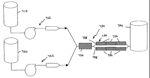
carrying out this process is shown in Figure 7. An organic phase 710
(polymer/drug
solution) is pumped by a pump 712. A continuous phase 720 (PVA solution) is
pumped by
a pump 722. The organic and continuous phases are pumped into a static mixing
assembly
730. Preferably, static mixing assembly 730 comprises a preblending static
mixer 732 and
a manifold 734. Manifold 734 preferably comprises a plurality of individual
static mixers
736 configured to provide a plurality of parallel flow streams 738. Although
Figure 7
shows two parallel flow streams in manifold 734, the present invention is not
limited to the
use of two flow streams, and more or less flow streams could be used in
manifold 734, as
would be readily apparent to one skilled in the art. Similarly, Figure 7 shows
three
1o individual static mixers 736 arranged in series to form flow streams 738.
It should be
readily apparent to one skilled in the art that other numbers, more or less,
of static mixers
736 could be used to form flow streams 738.
The emulsion droplet size, and the resulting microparticle size, are
controlled
primarily by the flow rate and residence time through the static mixing
assembly. The
static mixing assembly used in the 20 Kg risperidone process consisted of a
two inch
diameter preblending static mixer upstream of a two flow stream manifold. Each
flow
stream in the manifold was formed by three, eighteen inch long, one inch
diameter static
mixers arranged in series. The larger diameter of the preblending static mixer
is important
to accommodate the total flow from the organic and aqueous phase feed streams
at a lower
velocity than the smaller diameter static mixers in the manifold.
The flow rates are set by nominal pump speed settings. The total flow rate was
approximately 20-22 Kg/min, divided between the two flow streams in the
manifold. The
total flow rate can be divided one-half for each flow stream in the manifold,
or in any other
manner as would be readily apparent to one skilled in the art.
The flow rates for seven 20 Kg batches of microparticles are shown below in
Table
4. In batches 03098, 03168, and 03238, the drug (risperidone) was not present,
resulting in
the production of "placebo" microparticles.
-15-
CA 02390284 2002-05-07
WO 01/34113 PCT/US00/41842
Table 4 20kg Emulsion flow rate summary
Batch w:o ratio Rate water Rate oil Rate Total
w/w kg/min k min k min
-03098 4.84 16.8 3.47 20.3
-03168 4.84 16.8 3.47 20.3
-03238 4.86 16.8 3.47 20.3
-03308 4.70 16.8 3.57 20.3
-04068 4.67 17.0 3.63 20.6
-04138 4.50 16.9 3.75 20.7
-04208 4.46 16.8 3.78 20.6
Average 4.7 16.8 3.6 20.4
SD 0.2 0.1 0.1 0.2
After exiting the static mixing assembly, the oil-in-water emulsion is
transferred to
a large agitated tank for solvent extraction or quench (extraction vessel 740
in Figure 7).
The aqueous quench consisted of 4875 Kg WFI and 125 Kg ethyl acetate at 6 C.
Solvents are extracted from the emulsion droplets, thereby hardening into
microparticles.
The microparticles were sampled from the extraction vessel and analyzed using
a Coulter
LQ100 particle size analyzer. The particle size results from these experiments
are shown
below in Table 5.
Batch # Particle Size Characteristics
Mean (um Std. Dev. % < 150um
0309-8 83.03 40.44 95.7
0316-8 80.14 43.79 94.5
0323-8 80.81 40.81 95.8
0330-8 82.24 36.9 97.7
0406-8 78.21 34.53 99
0413-8 80.47 35.31 98.5
0420-8 79.55 35.75 98.5
Average 80.64 38.22 97.10
Std. Dev 1.62 3.48 1.75
Table 5
As can be seen from Table 5, the percentage of microparticles within the
desired
microparticle size range of less than 150 gm ranged from 94.5% to 99%, with an
average
of 97.1%. Through the use of the static mixing assembly, the particle size
characteristics
could be controlled to provide a desired microparticle size range.
It should be understood by one skilled in the art that the present invention
is not
limited to the use of an individual static mixer for any of the elements
depicted as
individual static mixers in the Figures. As would be readily apparent to one
skilled in the
-16-
CA 02390284 2002-05-07
WO 01/34113 PCT/US00/41842
art, a plurality of individual static mixers arranged in series could be used,
or a manifold
containing a plurality of individual static mixers arranged in series, or
arranged in parallel
to provide a plurality of parallel flow streams, could also be used.
Exan:ple 3 - Methods for Preparing Microparticles
As exemplified by the examples discussed above, methods for preparing
microparticles in accordance with the present invention will now be described
in more
detail. In one embodiment of the present invention, a first phase, comprising
an active
agent and a polymer, is prepared. In one embodiment of the present invention,
the first
phase is prepared by dissolving the active agent in a first solvent to form an
active agent
solution. The polymer is dissolved in a second solvent to form a polymer
solution. The
active agent solution and the polymer solution are blended to form the first
phase. In a
particularly preferred embodiment, the active agent is selected from the group
consisting of
risperidone, 9-hydroxyrisperidone, and pharmaceutically acceptable salts
thereof. In such
an embodiment, a preferred first solvent is benzyl alcohol, and a preferred
second solvent
is ethyl acetate.
In another embodiment of the present invention, the first phase is prepared by
dissolving the active agent and the polymer in a solvent to form a solution.
In a
particularly preferred embodiment, the active agent is bupivacaine, and the
solvent is ethyl
acetate. It should be understood that the present invention is not limited to
any particular
method or process by which the first phase is prepared, and other suitable
processes would
be readily apparent to one skilled in the art.
A second phase is prepared, and combined with the first phase in a first
static mixer
to form an emulsion. In a preferred embodiment, the two phases are pumped into
the static
mixer, with the second phase being pumped at a flow rate greater than the flow
rate of the
first phase. In one preferred embodiment, the ratio of the flow rate of the
second phase to
the flow rate of the first phase is from about 4:1 to about 5:1. However, it
should be
understood by one skilled in the art that the present invention is not limited
to such a flow
rate ratio, and other appropriate flow rate ratios would be readily apparent
to one skilled in
the art.
The emulsion flows through a manifold that includes a plurality of static
mixers
into a quench liquid whereby droplets of the emulsion form microparticles. The
quench
-17-
CA 02390284 2002-05-07
WO 01/34113 PCTIUSOO/41842
liquid is prepared in a manner well known to one skilled in the art. The
quench may be
water, such as WFI or it may be an aqueous solution comprising one or more
solvents.
Preferably, the diameter of the first static mixer is greater than the
diameter of each
of the plurality of static mixers in the manifold. In one embodiment, the
plurality of static
mixers is configured to provide a plurality of parallel flow streams. In a
particularly
preferred embodiment, the plurality of static mixers in the manifold is two.
However, it
should be understood by one skilled in the art that the present invention is
not limited to
the use of two static mixers in such a configuration, and other appropriate
numbers of static
mixers would be readily apparent to one skilled in the art. Alternatively, the
plurality of
static mixers can be configured in series to provide a plurality of sequential
flow streams.
The step of flowing the emulsion through the manifold is preferably performed
by
flowing a portion of a total flow rate through each of the static mixers in
the manifold, the
total flow rate being the sum of the flow rate of the first phase and the flow
rate of the
second phase. For example, for a manifold configured with two static mixers, a
portion of
the total flow rate will flow through each of the two static mixers. The
portion flowing
through each of the two static mixers can be one-half, or other portions as
would be readily
apparent to one skilled in the art.
An alternate method for preparing microparticles in accordance with the
present
invention will now be described. A first phase, comprising an active agent and
a polymer,
is prepared. A second phase is prepared, and combined with the first phase in
a first static
mixer to form an emulsion, the emulsion forming an outflow of the first static
mixer.
Suitable methods and processes for preparing the first and second phases, and
for
combining in the first static mixer, have been described above and will not be
repeated
here for brevity.
The outflow of the first static mixer is divided to form at least two flow
streams.
Each of the at least two flow streams flows through a separate second static
mixer. The
separate second static mixer can be an individual static mixer, one of a
plurality of
individual static mixers arranged in series, or one of a plurality of
individual static mixers
configured to provide a plurality of parallel flow streams. Preferably, the
diameter of the
first static mixer is greater than the diameter of each separate second static
mixer. The at
least two flow streams may have substantially equal flow rates, or such other
flow rates as
would be apparent to one skilled in the art.
-18-
CA 02390284 2002-05-07
WO 01/34113 PCTIUSOO/41842
The at least two flow streams are combined with a quench liquid whereby
droplets
of the emulsion form microparticles. The quench liquid can be the same as, or
different
from, the second phase.
A method for controlling particle size distribution of microparticles in
accordance
with the present invention will now be described. In a manner as described
above, a first
phase, comprising an active agent and a polymer, is prepared. A second phase
is prepared,
and combined with the first phase in a static mixing assembly to form an
emulsion. The
emulsion flows into a quench liquid whereby droplets of the emulsion form
microparticles.
The residence time of the emulsion in the static mixing assembly is adjusted
to obtain a
1 o predetermined particle size distribution of the resulting microparticles.
The residence time
is equal to a length of the static mixing assembly divided by an average
velocity of the
emulsion through the static mixing assembly. Increasing the residence time of
the
emulsion in the static mixing assembly narrows the particle size distribution.
Similarly,
decreasing the residence time of the emulsion in the static mixing assembly
broadens the
particle size distribution. The residence time may be adjusted by changing the
length of
the static mixing assembly. In one embodiment, the residence time is from
about three
seconds to about four seconds. However, it should be understood by one skilled
in the art
that the present invention is not limited to such a residence time, and other
residence times
may be used.
In one embodiment of the present invention, the static mixing assembly
comprises
a plurality of individual static mixers configured so that the emulsion flows
sequentially
through the plurality of individual static mixers. In an alternate embodiment,
the static
mixing assembly comprises a first static mixer and a manifold, in fluid
communication
with the first static mixer, which includes a plurality of static mixers. In
such an alternate
embodiment, the diameter of the first static mixer is preferably greater than
the diameter of
each of the plurality of static mixers in the manifold.
Microparticles of the Present Invention
The microparticles prepared by the process of the present invention preferably
comprise a polymeric binder, but it should be understood by one skilled in the
art that the
present invention is not limited to preparation of microparticles comprising a
polymeric
binder. Suitable polymeric binder materials include poly(glycolic acid), poly-
d,l-lactic
acid, poly-l-lactic acid, copolymers of the foregoing, poly(aliphatic
carboxylic acids),
-19-
CA 02390284 2002-05-07
WO 01/34113 PCT/US00/41842
copolyoxalates, polycaprolactone, polydioxanone, poly(ortho carbonates),
poly(acetals),
poly(lactic acid-caprolactone), polyorthoesters, poly(glycolic acid-
caprolactone),
polyanhydrides, polyphosphazines, albumin, casein, and waxes. Poly (d,l-lactic-
co-glycolic
acid) is commercially available from Alkermes, Inc. (Blue Ash, OH). A suitable
product
commercially available from Alkermes, Inc. is a 50:50 poly(d,l-lactic-co-
glycolic acid)
known as MEDISORB 5050 DL. This product has a mole percent composition of 50%
lactide and 50% glycolide. Other suitable commercially available products are
MEDISORB 6535 DL, 7525 DL, 8515 DL and poly(d,l-lactic acid) (100 DL).
Poly(lactide-co-glycolides) are also commercially available from Boehringer
Ingelheim
1o (Germany) under its Resomer mark, e.g., PLGA 50:50 (Resomer(b RG 502),
PLGA
75:25 (Resomer RG 752) and d,l-PLA (Resomer(E RG 206), and from Birmingham
Polymers (Birmingham, Alabama). These copolymers are available in a wide range
of
molecular weights and ratios of lactic acid to glycolic acid.
One type of microparticle suitable for preparation by the present invention is
a
sustained-release microparticle that is biodegradable. However, it should be
understood by
one skilled in the art that the present invention is not limited to
biodegradable or other
types of sustained-release microparticles. As would be apparent to one skilled
in the art,
the molecular weight of the polymeric binder material for biodegradable
microparticles is
of some importance. The molecular weight should be high enough to permit the
formation
of satisfactory polymer coatings, i.e., the polymer should be a good film
former. Usually,
a satisfactory molecular weight is in the range of 5,000 to 500,000 daltons,
preferably
about 150,000 daltons. However, since the properties of the film are also
partially
dependent on the particular polymeric binder material being used, it is very
difficult to
specify an appropriate molecular weight range for all polymers. The molecular
weight of
the polymer is also important from the point of view of its influence upon the
biodegradation rate of the polymer. For a diffusional mechanism of drug
release, the
polymer should remain intact until all of the drug is released from the
microparticles and
then degrade. The drug can also be released from the microparticles as the
polymeric
binder bioerodes. By an appropriate selection of polymeric materials a
microparticle
formulation can be made in which the resulting microparticles exhibit both
diffusional
release and biodegradation release properties. This is useful in according
multiphasic
release patterns.
-20-
CA 02390284 2007-08-08
77223-12
The microparticles prepared in accordance with the present invention may
include
an active agent or other type of substance that is released from the
microparticles into the
host. Such active agents can include 1,2-benzazoles, more particularly, 3-
piperidinyl-
substituted 1,2-benzisoxazoles and 1,2-benzisothiazoles. The most preferred
active agents
of this kind are 3-[2-[4-(6-fluoro-1,2-benzisoxazol-3-yl)-1-piperidinyl]ethyl]-
6,7,8,9-
tetrahydro-2-methyl-4H--pyrido[1,2-a]pyrimidin-4-one ("risperi done") and 3-[2-
[4-(6-
fluro-1,2-benzisoxazol-3-yl)-1-piperidinyl] ethyl]-6,7,8,9-tetrahydro-9-hydrox
y-2-methyl-
4H--pyrido[1,2-a]pyrimidin-4-one ("9-hydroxyrispendone") and the
pharmaceutically
acceptable salts thereof. Risperidone (which term, as used herein, is intended
to include its
to pharmaceutically acceptable salts) is most preferred. Risperidone can be
prepared in
accordance with the teachings of U.S. Patent No. 4,804,663, the entirety of
which is
incorporated herein by reference. 9-hydroxyrisperidone can be prepared in
accordance
with the teachings of U.S. Patent No. 5,158,952.
Other biologically active agents include non-steroidal antifertility agents;
parasympathonmimetic agents; psychotherapeutic agents; major tranquilizers
such as
chlorpromazine HC 1, clozapine, mesoridazine, metiapine, reserpine,
thioridazine and the
like; minor tranquilizers such as chlordiazepoxide, diazepanrn meprobamate,
temazepam
and the like; rhinological decongestants; sedative-hypnotics such as codeine,
phenobarbital, sodium pentobarbital, sodium secobarbital and the like;
steroids such as
testosterone and tesosterone propionate; sulfonamides; sympathornimetic
agents; vaccines;
vitamins and nutrients such as the essential amino acids; essential fats and
the like;
antimalarials such 4-aminoquinolines, 8-aminoquinolines, pyrimethamine and the
like,
anti-migraine agents such as mazindol, phentermine and the like; anti-
Parkinson agents
such as L-dopa; anti-spasmodics such as atropine, methscopolamine bromide and
the like;
antispasmodics and anticholinergic agents such as bile therapy, digestants,
enzymes and
the like; antitussives such as dextromethorphan, noscapine and the like;
bronchodilators;
cardiovascular agents such as anti-hypertensive compounds, Rauwolfia
alkaloids, coronary
vasodilators, nitroglycerin, organic nitrates, pentaerythritotetranitrate and
the like;
electrolyte replacements such as potassium chloride; ergotalkaloids such as
ergotamine
with and without caffeine, hydrogenated ergot alkaloids, dihydroergocristine
methanesulfate, dihydroergocornine methanesulfonate, dihydroergokroyptine
methanesulfate and combinations thereof; alkaloids such as atropine sulfate,
Belladonna,
-21-
CA 02390284 2002-05-07
WO 01/34113 PCTIUSOO/41842
hyoscine hydrobromide and the like; analgetics, narcotics such as codeine,
dihydrocodienone, meperidine, morphine and the like; non-narcotics such as
salicylates,
aspirin, acetaminophen, d-propoxyphene and the like; antibiotics such as
salicylates,
aspirin, acetaminophen, d-propoxyphene and the like; antibiotics such as the
cephalosporins, chloranphenical, gentamicin, Kanamycin A, Kanamycin B, the
penicillins,
ampicillin, streptomycin A, antimycin A, chloropamtheniol, metromidazole,
oxytetracycline penicillin G, the tetracylines, and the like, anti-cancer
agents; anti-
convulsants such as mephenytoin, phenobarbital, trimethadione; anti-emetics
such as
thiethylperazine; antihistamines such as chlorophinazine, dimenhydrinate,
l0 diphenhydramine, perphenazine, tripelennamine and the like; anti-
inflammatory agents
such as hormonal agents, hydrocortisone, prednisolone, prednisone, non-
hormonal agents,
allopurinol, aspirin, indomethacin, phenylbutazone and the like;
prostaglandins; cytotoxic
drugs such as thiotepa; chlorambucil, cyclophosphamide, melphalan, nitrogen
mustard,
methotrexate and the like; antigens of such microorganisms as Neisseria
gonorrhea,
Mycobacterium tuberculosis, Herpes virus (homonis, types 1 and 2), Candida
albicans,
Candida tropicalis, Trichomonas vaginalis, Haemophilus vaginalis, Group B
Streptococcus ecoli, Mycoplasma hominis, Haemophilus ducreyi, Granuloma
inguinale,
Lymphopathia venereum, Treponema pallidum, Brucella abortus, Brucella
melitensis,
Brucella suis, Brucella canis, Campylobacter fetus, Campylobacter fetus
intestinalis,
Leptospira pomona, Listeria monocytogenes, Brucella ovis, Equine herpes virus
1, Equine
arteritis virus, IBR-IBP virus, BVD-MB virus, Chiamydia psittaci, Trichomonas
foetus,
Toxoplasma gondii, Escherichia coli, Actinobacillus equuli, Salmonella abortus
ovis,
Salmonella abortus equi, Pseudomonas aeruginosa, Corynebacterium equi,
Corynebacterium pyogenes, Actinobacillus seminis, Mycoplasma bovigenitalium,
Aspergillus fumigatus, Absidia ramosa, Trypanosoma equiperdum, Babesia
caballi,
Clostridium tetani, and the like; antibodies that counteract the above
microorganisms; and
enzymes such as ribonuclease, neuramidinase, trypsin, glycogen phosphorylase,
sperm
lactic dehydrogenase, sperm hyaluronidase, adenosinetriphosphatase, alkaline
phosphatase,
alkaline phosphatase esterase, amino peptidase, trypsin, chymotrypsin,
amylase,
muramidase, acrosomal proteinase, diesterase, glutamic acid dehydrogenase,
succinic acid
dehydrogenase, beta-glycophosphatase, lipase, ATP-ase alpha-peptate gamma-
glutamylotranspeptidase, sterol-3-beta-ol-dehydrogenase, and DPN-di-aprorasse.
-22-
CA 02390284 2002-05-07
WO 01/34113 PCT/US00/41842
Other suitable active agents include estrogens such as diethyl stilbestrol, 17-
beta-
estradiol, estrone, ethinyl estradiol, mestranol, and the like; progestins
such as
norethindrone, norgestryl, ethynodiol diacetate, lynestrenol,
medroxyprogesterone acetate,
dimesthisterone, megestrol acetate, chlormadinone acetate, norgestimate,
norethisterone,
ethisterone, melengestrol, norethynodrel and the like; and the spermicidal
compounds such
as nonylphenoxypolyoxyethylene glycol, benzethonium chloride, chlorindanol and
the
like.
Still other suitable active agents include antifungals, antivirals,
anticoagulants,
anticonvulsants, antidepressants, antihistamines, hormones, vitamins and
minerals,
cardiovascular agents, peptides and proteins, nucleic acids, immunological
agents, antigens
of such bacterial organisms as Streptococcus pneumoniae, Haemophilus
influenzae,
Staphylococcus aureus, Streptococcus pyogenes, Corynebacterium diphtheriae,
Bacillus
anthracis, Clostridium tetani, Clostridium botulinum, Clostridiunz
perfringens,
Streptococcus mutans, Salmonella typhi, Haemophilus parainfluenzae, Bordetella
pertussis, Francisella tularensis, Yersinia pestis, Vibrio cholerae,
Legionella pneumophila,
Mycobacterium leprae, Leptospira interrogans, Borrelia burgdorferi,
Campylobacter
jejuni, antigens of such viruses as smallpox, influenza A and B, respiratory
syncytial,
parainfluenza, measles, HIV, varicella-zoster, herpes simplex 1 and 2,
cytomegalovirus,
Epstein-Barr, rotavirus, rhinovirus, adenovirus, papillomavirus, poliovirus,
mumps, rabies,
rubella, coxsackieviruses, equine encephalitis, Japanese encephalitis, yellow
fever, Rift
Valley fever, lymphocytic choriomeningitis, hepatitis B, antigens of such
fungal protozoan,
and parasitic organisms such as Cryptococcus neoformans, Histoplasma
capsulatum,
Candida albicans, Candida tropicalis, Nocardia asteroides, Rickettsia
ricketsii, Rickettsia
typhi, Mycoplasma pneumoniae, Chlamydia psittaci, Chlamydia trachomatis,
Plasmodium
falciparum, Trypanosoma brucei, Entamoeba histolytica, Toxoplasma gondii,
Trichomonas vaginalis, Schistosoma mansoni. These antigens may be in the form
of
whole killed organisms, peptides, proteins, glycoproteins, carbohydrates, or
combinations
thereof.
Still other macromolecular bioactive agents that may be chosen for
incorporation
include, but are not limited to, blood clotting factors, hemopoietic factors,
cytokines,
interleukins, colony stimulating factors, growth factors, and analogs and
fragments thereof.
The microparticles can be mixed by size or by type. However, it should be
understood that the present invention is not limited to the use of
biodegradable or other
-23-
CA 02390284 2002-05-07
WO 01/34113 PCT/US00/41842
types of microparticles that contain an active agent. In one embodiment, the
microparticles
are mixed in a manner that provides for the delivery of active agent to the
patient in a
multiphasic manner and/or in a manner that provides different active agents to
the patient
at different times, or a mixture of active agents at the same time. For
example, secondary
antibiotics, vaccines, or any desired active agent, either in microparticle
form or in
conventional, unencapsulated form can be blended with a primary active agent
and
provided to the patient.
Conclusiou
While various embodiments of the present invention have been described above,
it
1 o should be understood that they have been presented by way of example only,
and not
limitation. The present invention is not limited to the preparation of
controlled release
microparticles, nor is it limited to a particular active agent, polymer or
solvent, nor is the
present invention limited to a particular scale or batch size. The present
invention is not
limited to any type or design of static mixer. Thus, the breadth and scope of
the present
invention should not be limited by any of the above-described exemplary
embodiments,
but should be defined only in accordance with the following claims and their
equivalents.
-24-