Language selection

Search

Patent 2390537 Summary

Third-party information liability

Some of the information on this Web page has been provided by external sources. The Government of Canada is not responsible for the accuracy, reliability or currency of the information supplied by external sources. Users wishing to rely upon this information should consult directly with the source of the information. Content provided by external sources is not subject to official languages, privacy and accessibility requirements.

Claims and Abstract availability

Any discrepancies in the text and image of the Claims and Abstract are due to differing posting times. Text of the Claims and Abstract are posted:

  • At the time the application is open to public inspection;
  • At the time of issue of the patent (grant).
(12) Patent: (11) CA 2390537
(54) English Title: FLEXIBLE PIPE INCLUDING VENT PASSAGE AND METHOD OF MANUFACTURING SAME
(54) French Title: TUYAU SOUPLE DOTE D'UN PASSAGE D'AERATION ET PROCEDE DE FABRICATION CORRESPONDANT
Status: Deemed expired
Bibliographic Data
(51) International Patent Classification (IPC):
  • F16L 11/10 (2006.01)
  • B29D 23/00 (2006.01)
  • F16L 11/08 (2006.01)
(72) Inventors :
  • FRASER, DANA J. (United States of America)
  • KALMAN, MARK D. (United States of America)
(73) Owners :
  • GE OIL & GAS UK LIMITED (United Kingdom)
(71) Applicants :
  • WELLSTREAM, INC. (United States of America)
(74) Agent: GOWLING WLG (CANADA) LLP
(74) Associate agent:
(45) Issued: 2008-07-15
(86) PCT Filing Date: 2000-11-04
(87) Open to Public Inspection: 2001-05-10
Examination requested: 2004-12-07
Availability of licence: N/A
(25) Language of filing: English

Patent Cooperation Treaty (PCT): Yes
(86) PCT Filing Number: PCT/US2000/030513
(87) International Publication Number: WO2001/033130
(85) National Entry: 2002-05-03

(30) Application Priority Data:
Application No. Country/Territory Date
60/163,908 United States of America 1999-11-05
09/705,309 United States of America 2000-11-03

Abstracts

English Abstract


The present invention provides a flexible multi-layer pipe
comprising an inner tubular layer defining an inner
longitudinal passage and at least one longitudinally
extending tube embedded in the inner layer and extending
for the length of the inner layer, the tube adapted to
receive any gases permeating through or into the inner
tubular layer and vent the gases from the pipe.


French Abstract

L'invention se rapporte à un tuyau souple (10) composé de multiples couches (12, 14, 15, 16, 18, 20) de matières différentes, dont l'une comporte un passage d'aération (22).

Claims

Note: Claims are shown in the official language in which they were submitted.


4

Claims:

1. A flexible pipe comprising an inner tubular layer defining an inner
longitudinal
passage; at least one longitudinally extending tube embedded in the inner
layer and
extending for the length of the inner layer, the tube adapted to receive any
gases
permeating through or into the inner tubular layer and vent the gases from the
pipe; and an
outer layer extending over the inner layer.


2. The pipe of claim 1 wherein a plurality of openings are formed through the
tube to
receive the gases.


3. The flexible pipe of claim 1 wherein a plurality of tubes is angularly
spaced around
the axis of the inner layer.


4. The flexible pipe of claim 1 wherein the outer layer comprises a metal
strip layer
helically wound over the inner layer.


5. The flexible pipe of claim 4 further comprising a seal layer extending over
the metal
strip layer.


6. The flexible pipe of claim 5 further comprising at least one wire wrapped
around the
exterior of the seal layer to form a tensile layer.


7. The flexible pipe of claim 6 further comprising at least one wire wrapped
around the
tensile layer to form an additional tensile layer.


8. The flexible pipe of claim 1 wherein the outer layer comprises at least one
wire
wrapped around the exterior of the inner layer to form a tensile layer.


9. The flexible pipe of claim 8 wherein the outer layer further comprises at
least one
wire wrapped around the ensile layer to form an additional tensile layer.


10. The flexible pipe of claim 1, 4, 5, 6, 7, 8 or 9 further comprising a
layer of wound
tape extending between adjacent layers.


11. A method of manufacturing a flexible pipe, comprising forming at least one
tube,
embedding the tube along the length of an inner tubular layer defining an
inner longitudinal
passage so that any gases received by the layer and permeating through or into
the layer
pass into the tube for discharge through an end of the tube, and disposing an
outer layer
over the inner layer.


12. The method of claim 11 further comprising forming a plurality of openings
through
the tube to receive the gases.


13. The method of claim 11 wherein the tubes are angularly spaced around the
axis of
the inner layer.


14. The method of claim 11 wherein the step of disposing comprises wrapping a
metal
strip layer over the inner layer.


15. The method of claim 14 further comprising disposing a seal layer over the
metal
strip layer.


16. The method of claim 15 further comprising wrapping at least one wire
around the
exterior of the seal layer to form a tensile layer.


17. The method of claim 16 further comprising wrapping at least one wire
around the
tensile layer to form an additional tensile layer.


18. The method of claim 11 wherein the step of disposing comprises wrapping at
least
one wire around the exterior of the inner layer to form a tensile layer.


6

19. The method of claim 18 wherein the step of disposing further comprises
wrapping
at least one wire around the tensile layer to form an additional tensile
layer.


20. The method of claim 11 and 14, 15, 16, 17, 18 or 19 further comprising
wrapping a
tape between adjacent layers.


21. A flexible pipe, comprising:
an inner tubular member defining an inner longitudinal passage and having an
undulating outer surface forming a series of ridges and valleys; and
a metal strip helically wound over the tubular member wherein the ridges and a

corresponding inner surface of the layer formed by the wound metal strip form
a plurality of
vent passages, the vent passages venting to an end of the tubular member any
fluids that
may permeate through the tubular member.


22. The pipe of claim 21 further comprising a seal layer, in the form of an
extruded
plastic sheath, extending over the metal strip.


23. The pipe of claim 22 further comprising at least one layer of wires
wrapped helically
around the seal layer.


24. The pipe of claim 23 wherein there are two layers of wires.


25. The pipe of claim 23 wherein the wires of one layer of wires are wrapped
in an
opposite direction to the wires of the other layer of wires.


26. The pipe of claim 23 wherein a plurality of vent passages are formed
between
adjacent wires of each layer of wires.


27. The pipe of claim 23 further comprising at least one layer of tape
extending over at
least one layer of wires.


7

28. The pipe of claim 27 further comprising an insulative layer, in the form
of an
extruded plastic sheath, extending over the layer of tape.


29. The pipe of claim 21 further comprising at least one layer of wires
wrapped helically
around the metal strip.


30. The pipe of claim 29 wherein there are two layers of wires.


31. The pipe of claim 29 further comprising a seal layer extending over at
least one
layer of wires.


32. The pipe of claims 31 further comprising an additional layer of wires
wrapped
helically around the seal layer.


33. The pipe of claim 32 wherein the wires of one of the layers of wires are
wrapped in
an opposite direction to the wires of the other layer of wires.


34. The pipe of claim 29 wherein a plurality of vent passages are formed
between
adjacent wires of each layer of wires.


35. The pipe of claim 32 further comprising a seal layer, in the form of an
extruded
plastic sheath, extending over the additional layer of wires.


36. The pipe of claim 31 or 35 further comprising at least one layer of tape
extending
over the seal layer.


37. The pipe of claim 36 further comprising an insulative layer, in the form
of an
extruded plastic sheath, extending over the layer of tape.


38. A method of manufacturing a flexible pipe, comprising:


8

forming an undulating outer surface on an inner tubular member so that the
outer
surface forms a series of ridges and valleys; and
winding a metal strip over the tubular member to form a layer around the outer

surface of the tubular member whereby the ridges and a corresponding inner
surface of the
layer form a plurality of vent passages so that any fluids that may permeate
through the
tubular member are vented through the vent passages to an end of the tubular
member.

39. The method of claim 38 further comprising providing a seal layer, in the
form of an
extruded plastic sheath, over the metal strip.


40. The method of claim 39 further comprising wrapping at least one layer of
wires
around the seal layer.


41. The method of claim 40 wherein there are two layers of wire.


42. The method of claim 41 wherein the wires of one of the layers of wire are
wrapped
in an opposite direction to the wires of the other layer of wires.


43. The method of claim 40 wherein a plurality of vent passages are formed
between
adjacent wires of each layer of wires.


44. The method of claim 40 further comprising wrapping at least one layer of
tape over
at least one layer of wires.


45. The method of claim 44 further comprising providing an insulative layer,
in the form
of an extruded plastic sheath, over the layer of tape.


46. The method of claim 38 further comprising wrapping at least one layer of
wires
around the metal strip.


47. The method of claim 46 wherein there are two layers of wires.


9

48. The method of claim 46 further comprising providing a seal layer over the
at least
one layer of wires.


49. The method of claim 48 further comprising wrapping an additional layer of
wires
around the seal layer.


50. The method of claim 47 wherein the wires of one of the layers of wires are
wrapped
in an opposite direction to the wires of the other layer of wires.


51. The method of claim 47 wherein a plurality of vent passages are formed
between
adjacent wires of each layer of wires.


52. The method of claim 51 further comprising providing a seal layer, in the
form of an
extruded plastic sheath, extending over the additional layer of wires.


53. The method of claim 51 further comprising wrapping at least one layer of
tape
extending over the seal layer.


54. The method of claim 53 further comprising providing an insulative layer,
in the form
of an extruded plastic sheath, over the layer of tape.

Description

Note: Descriptions are shown in the official language in which they were submitted.


4 1 CA 02390537 2007-01-30

WO 01/33130 PCT/US00/30513
-1-
FLEXIBLE PIPE INCLUDING VENT PASSAGE AND METHOD OF MANUFACTURING SAME

This invention relates to a flexible pipe according to which the
pipe is formed by multiple layers of different materials, one of
which has a vent passage.
Brief Description of the Drawing
Fig. 1 is a longitudinal sectional view of a flexible pipe
according to an embodiment of the present invention.
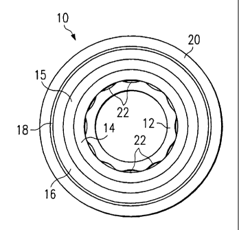
Fig. 2 is an end view of the pipe of Fig. 1.
Detailed Description
With reference to Fig. 1, a flexible pipe according to an
embodiment of the present invention is shown, in general by the
reference numeral 10. The pipe 10 is formed by an inner layer 12,
preferably in the form of an extruded plastic sheath, for conveying
fluid through its bore. As shown in Fig. 2, the outer surface of the
layer 12 is undulated thus forming a series of ridges and valleys for
reasons to be described. The layer 12 may be formed in a
conventional manner using polymers, or the like.
A layer 14 extends around the layer 12 and provides resistance
to internal pressure, hydrostatic collapse and crush. The layer 14
is formed by helically wrapping a continuous metal strip, preferably
formed of carbon steel, with adjacent windings being interlocked, to
form a flexible layer that provides significant hoop and axial
strength. The layer 14 is marketed by the assignee of the present
invention, Welistream, Inc., under the "Flexlok" trademark.
Alternatively, the layer 14 can be of another type.
A seal layer 15, preferably in the form of an extruded plastic
sheath, is provided over the layer 14 to increase the resistance to
hydrastatic compression, and assist in limiting the moisture that
permeates from the bores of the layer 12.
A layer'16 of wrapped wires extends over the layer 15 and


CA 02390537 2002-05-03

WO 01/33130 PCT/US00/30513
-2-
consists of a series of wires 16a helically wrapped around the
exterior of the layer 15 to form a first tensile layer, and an
additional series of wires 16b wrapped around the first series of
wires 16a to form a second tensile layer extending over the first
tensile layer. The wires 16a and 16b have a circular cross section,
and are wound at a relatively high lay angle to provide significant
hoop strength and axial strength. Preferably, at least a portion of
the wires 16a and 16b are formed by carbon steel with a plastic or
anodic coating. It is noted that the layers 14 and 15 prevent the
expansion of the layer 12 into gaps formed between the wires of the
tensile layers 16a and 16b.
A layer 18 is formed by helically wrapping tape over the layer
16. The tape forming the layer 18 can be plastic or metal and can be
reinforced with glass, metal or a different type of plastic.
Although not shown in the drawings, it is understood that the tape
layer 18 can also extend between the layer 14 and the layer 16, and
between the series of wires 16a and 16b.
A protective outer layer 20, in the form of an insulative
sheath, extends over the tape layer 18 and is preferably in the form
of an extruded plastic sheath that extends over the tape layer in a
conventional manner, with the tape providing a smooth surface for the
extrusion. The layer 20 is optional and is required only when the
tape layer is inadequate to protect the remaining components of the
pipe 10.
In operation, when the pipe 10 is put into service the ridges
formed by the undulating outer surface of the layer 12, and the
corresponding inner surface of the layer 14, form passages 22 for
venting any gases that might permeate through the layer 12. These
passages extend for the length of the pipe 10 and can discharge into
atmosphere at one of the ends of the pipe.
Variations
1. Additional tensile layers of wires can be provided in addition
to the series of wires 16a and 16b.
2. The vent passages can be formed by longitudinal strips extending
over the outer surface of the layer 12.
3. A plurality of longitudinal tubes could be imbedded in one or


CA 02390537 2002-05-03

WO 01/33130 PCTIUSOO/30513
-3-
more of the layers 12, 14, 15, 16, 18, and 30 to provide the vent
passages.
4. Rather than providing the sheath 12 with an undulating outer
surface, longitudinal grooves or slots can be provided in the outer
surface to form the vent passages.
5. The seal layer 15 can extend over the layer 16 or between the
tensile layers formed by the wires 16a and 16b, in which case the
venting would be between the adjacent wires 16a.
6. The adjacent windings of the strip forming the layer 14 do not
have to be interlocked.
7. The cross section of the wires 16a and 16b can be rectangular as
disclosed in the above cited application.
8. In extremely hostile environments, an outer layer similar to the
layer 14 can be placed around the sheath 20 for added protection.
It is understood that spatial references, such as "under",
"over", "between", "outer", "inner" and "surrounding" are for the
purpose of illustration only and do not limit the specific
orientation or location of the layers described above.
Since other modifications, changes, and substitutions are
intended in the foregoing disclosure, it is appropriate that the
appended claims be construed broadly and in a manner consistent with
the scope of the invention.

Representative Drawing
A single figure which represents the drawing illustrating the invention.
Administrative Status

For a clearer understanding of the status of the application/patent presented on this page, the site Disclaimer , as well as the definitions for Patent , Administrative Status , Maintenance Fee  and Payment History  should be consulted.

Administrative Status

Title Date
Forecasted Issue Date 2008-07-15
(86) PCT Filing Date 2000-11-04
(87) PCT Publication Date 2001-05-10
(85) National Entry 2002-05-03
Examination Requested 2004-12-07
(45) Issued 2008-07-15
Deemed Expired 2016-11-04

Abandonment History

There is no abandonment history.

Payment History

Fee Type Anniversary Year Due Date Amount Paid Paid Date
Registration of a document - section 124 $100.00 2002-05-03
Application Fee $300.00 2002-05-03
Maintenance Fee - Application - New Act 2 2002-11-04 $100.00 2002-09-20
Maintenance Fee - Application - New Act 3 2003-11-04 $100.00 2003-10-30
Registration of a document - section 124 $100.00 2004-03-05
Maintenance Fee - Application - New Act 4 2004-11-04 $100.00 2004-10-19
Request for Examination $800.00 2004-12-07
Maintenance Fee - Application - New Act 5 2005-11-04 $200.00 2005-10-06
Maintenance Fee - Application - New Act 6 2006-11-06 $200.00 2006-10-05
Maintenance Fee - Application - New Act 7 2007-11-05 $200.00 2007-10-09
Final Fee $300.00 2008-04-10
Maintenance Fee - Patent - New Act 8 2008-11-04 $200.00 2008-10-07
Maintenance Fee - Patent - New Act 9 2009-11-04 $200.00 2009-10-06
Maintenance Fee - Patent - New Act 10 2010-11-04 $250.00 2010-10-13
Maintenance Fee - Patent - New Act 11 2011-11-04 $250.00 2011-10-12
Maintenance Fee - Patent - New Act 12 2012-11-05 $250.00 2012-10-17
Maintenance Fee - Patent - New Act 13 2013-11-04 $250.00 2013-10-08
Registration of a document - section 124 $100.00 2014-10-31
Maintenance Fee - Patent - New Act 14 2014-11-04 $250.00 2014-11-03
Owners on Record

Note: Records showing the ownership history in alphabetical order.

Current Owners on Record
GE OIL & GAS UK LIMITED
Past Owners on Record
BLOSSOMGRANGE LIMITED
FRASER, DANA J.
KALMAN, MARK D.
WELLSTREAM INTERNATIONAL LIMITED
WELLSTREAM, INC.
Past Owners that do not appear in the "Owners on Record" listing will appear in other documentation within the application.
Documents

To view selected files, please enter reCAPTCHA code :


To view images, click a link in the Document Description column. To download the documents, select one or more checkboxes in the first column and then click the "Download Selected in PDF format (Zip Archive)" or the "Download Selected as Single PDF" button.

List of published and non-published patent-specific documents on the CPD .

If you have any difficulty accessing content, you can call the Client Service Centre at 1-866-997-1936 or send them an e-mail at CIPO Client Service Centre.


Document
Description 
Date
(yyyy-mm-dd) 
Number of pages   Size of Image (KB) 
Representative Drawing 2002-05-03 1 9
Abstract 2002-05-03 1 57
Claims 2002-05-03 5 168
Drawings 2002-05-03 1 19
Description 2002-05-03 3 126
Cover Page 2002-10-22 1 33
Claims 2004-07-16 7 186
Claims 2005-09-02 6 172
Description 2007-01-30 3 121
Abstract 2007-01-30 1 11
Representative Drawing 2008-06-16 1 11
Cover Page 2008-06-16 1 41
Correspondence 2003-10-09 1 15
PCT 2002-05-03 9 365
Assignment 2002-05-03 3 95
Assignment 2002-08-29 7 375
Correspondence 2002-08-29 1 38
Fees 2003-10-30 1 32
Fees 2005-10-06 1 33
Assignment 2004-03-05 9 240
Prosecution-Amendment 2004-07-16 8 215
Prosecution-Amendment 2005-03-03 2 62
Prosecution-Amendment 2004-12-07 1 31
Fees 2004-10-19 1 30
Prosecution-Amendment 2005-09-02 17 550
Prosecution-Amendment 2006-08-10 2 44
Fees 2006-10-05 1 39
Prosecution-Amendment 2007-01-30 4 137
Fees 2007-10-09 1 40
Correspondence 2008-04-10 2 49
Fees 2008-10-07 1 32
Fees 2009-10-06 1 31
Fees 2010-10-13 1 37
Assignment 2014-10-31 39 4,002