Note: Descriptions are shown in the official language in which they were submitted.
CA 02390584 2002-05-08
WO 01/36772 PCT/US00/21510
-1-
TITLE OF THE INVENTION
INTEGRATED OBSTACLE DETECTION SYSTEM
CROSS REFERENCE TO RELATED APPLICATIONS
N/A
STATEMENT REGARDING FEDERALLY SPONSORED RESEARCH OR
DEVELOPMENT
N/A
BACKGROUND OF THE INVENTION
The development of small, powerful motors over recent
decades and the desire for added convenience have led to an
increase in the number of settings in which a closure is
driven automatically across an aperture, rather than
requiring manual manipulation. For instance, power windows
for motor vehicles are commonplace today. Similarly,
closures such as hatches or doors are known to be driven by
such motors.
As a further advancement, these power-driven closures
have recently been provided with control circuitry which
recognizes a particular command or set of commands which
result in the automatic operation of the closure, without
the further input of an operator. In the vehicle setting,
this is recognized as the case of express-close or one-touch
close power windows. By briefly activating the window
control, an operator can cause the power window to travel
from any open position to a fully closed position.
CA 02390584 2002-05-08
WO 01/36772 PCT/US00/21510
-2-
With the convenience of such power-driven closures has
come a risk of entrapment, particularly for children and
animals. In the vehicle window or sunroof setting, several
distinct approaches have been taken towards detecting the
presence of an obstacle, such as a child, an animal, or an
inanimate object, and consequently overriding an express
close command to avoid trapping the obstacle by the closure.
One such approach involves the monitoring of the
current supplied to the closure actuating motor. Typically,
the motor opens and closes the closure in the aperture by
rotating a drive shaft or armature. The elements which
actually move the closure are typically in mechanical
communication with the drive shaft through one or more
gears. When the motor is activated, the motor current
fluctuates both as a result of variations in forces opposing
the motion as well as in a periodic fashion as a result of
the rotation of magnetic elements inside the motor. By
monitoring the fluctuation of the motor current with motor
rotation, a gauge of motor operation and closure travel may
be established. Thus, a known number of pulses that can be
derived from the periodic component in the motor drive
current may be equated to closure travel from a fully open
position to a fully closed position. This is commonly
referred to as motor current ripple counting.
A monitoring circuit associated with the closure
controls may be provided with a timer and a pre-established
threshold for a normal travel time for an associated closure
from a fully open to a fully closed state. By combining the
positional information gained by monitoring the motor drive
current with the time threshold, it may be established
whether a powered closure reached a fully closed state
within an acceptable time period. Additionally, if the
CA 02390584 2002-05-08
WO 01/36772 PCT/US00/21510
-3-
ripple frequency is monitored, an estimate of the velocity
of motion may be derived. If the closure does not reach a
fully closed state either in an acceptable time period or
the velocity decreases unexpectedly, then obstacle
entrapment may be inferred and a number of actions may be
taken, including the automatic reversal of the closure. An
obvious drawback to this form of obstacle detection and
entrapment avoidance is the fact that the obstacle must
actually be entrapped and thereby squeezed in order to be
successfully detected, before corrective action is taken
such as reversing the direction of travel of the closure.
This is referred to as a "contact" obstacle detection
system.
An alternative approach to obstacle detection involves
the use of a projected field or beam of electromagnetic
energy directed across the aperture or a portion thereof or
proximate thereto. Under normal circumstances, a pre-
established level of emitted energy will be detected by an
associated receiver. If an obstacle is present within the
field of energy adjacent or within the aperture, the emitted
field will be altered; the receiver circuitry detects a
variation in the amount of detected energy and, depending
upon the degree of the variation, invokes corrective action
such as the reversal of the closure. This system may be
referred to as a "non-contact" obstacle detection system.
This system may also experience certain deficiencies,
depending in part upon the geometry of the aperture, the
environment and the disposition of the energy emitter and
detector with respect to the aperture. For instance, one or
more "blind spots" may be present as the closure is moved
towards a closed position, resulting from interference by
the closure or the aperture structure. As the powered
CA 02390584 2002-05-08
WO 01/36772 PCT/US00/21510
-4-
closure nears the "closed" position within the aperture, it
enters what may be referred to as a "pinch zone," a region
in which a small obstacle such as a child's hand may be
present but which because of its size may be difficult to
detect through the monitoring of the power level of
reflected energy.
In summary, both of the existing approaches to obstacle
detection within an aperture having a power-driven closure,
when used alone, may suffer from the aforementioned
limitations which could result in injury to an obstacle
present in the path of the closure.
BRIEF SUMMARY OF THE INVENTION
The present invention relates to an obstacle detection
system for a power driven closure, the system combining the
beneficial aspects of the contact and non-contact systems
previously discussed while avoiding the deficiencies
characteristic of these systems when employed alone.
As noted, a non-contact system may perform adequately
over a majority of the range of motion for a respective
power-driven closure. However, as the closure reaches a
terminal portion of its travel path within the aperture, the
closure itself may interfere with and degrade the
performance of the system to a degree that smaller objects
may not be detected. Entrapment may then result.
To ensure the ability to detect objects in this region,
the presently disclosed invention combines a contact-based
system with a non-contact system. The combination may be
utilized over the entire range of travel of the closure, or
may be invoked only within the pinch zone, however that
region is defined. If the input from a contact-based system
is employed only within the pinch zone, a number of factors
CA 02390584 2002-05-08
WO 01/36772 PCT/US00/21510
-5-
may be utilized in determining the actual position of the
closure. For instance, a ripple count technique may be
utilized, or the non-contact system itself may have a
characteristic output once the closure is at a particular
position. A timer or clock source may also be utilized as
an input for the purpose of establishing the rate of
movement for the closure.
Alternatively, one or more switches may be utilized,
including a mechanical switch disposed in conjunction with
the closure. An optical switch including a feature disposed
in conjunction with the closure, such as a tab for
interrupting a beam of optical energy between an emitter and
a detector, may also be used.
A central controller may be used for coordinating the
inputs from the two systems, or a controller associated with
one of these systems may be adapted for this purpose. If a
central controller is employed, it may be a controller
dedicated to this function, or one which is already utilized
in the environment of the aperture for another purpose.
The presently disclosed system may also be adapted to
respond to a broad range of inputs from the two systems and
to provide an appropriate response thereto. If the non-
contact system does not report uncharacteristic performance
during the terminal portion of closure travel, but the
contact-based system indicates that the closure is
travelling slower than expected, various inferences may be
made. It may be indicated that an obstacle is present.
Alternatively, it may be determined that there exists a
general degradation in the closure motor, a temperature-
related response by the closure motor, or dirt or ice
buildup on the closure. Depending on the environment in
which the closure is expected to be located, various
CA 02390584 2002-05-08
WO 01/36772 PCT/US00/21510
-6-
combinations of inputs may result in the determination that
an obstacle is present.
Conversely, if the non-contact system detects returned
energy levels outside predetermined norms, normally an
indication of the presence of an obstacle, but the contact
based system does not register aberrant performance of the
closure, the combined system may declare the absence of an
obstacle. The controller may then utilize the measurements
of the non-contact system to adjust the non-contact system
parameters. This adjustment may take a variety of forms,
including averaging returns over a number of cycles and
adjusting threshold values based on the averaged returns,
such as by an certain percentage of the average returned
energy in the absence of an obstacle. Further, the average
returned energy under these circumstances may be used as a
new center-point for a range of acceptable energy values.
A further advantage of combining these systems into a
new hybrid system is a failsafe mode of operation. If the
non-contact system fails due to an inoperative or obstructed
emitter or receiver, the contact system may be relied upon
solely by the joint controller. Conversely, if the contact-
based system loses the ability to track closure motion or
location, the non-contact system may be relied upon by the
joint controller. In conjunction with these modes of
operation, a warning may be provided to an operator of this
impaired state in the hybrid system and/or a log of the
event may be recorded in memory associated with the joint
controller for subsequent reference by maintenance
personnel.
Yet another advantage afforded by the presently
disclosed hybrid system is the ability to provide a reliable
indication of the completion of an express close operation.
CA 02390584 2002-05-08
WO 01/36772 PCT/US00/21510
With a non-contact system, such an indication may be
inferred, but with a lower degree of confidence.
Thus, a more accurate, flexible system for obstacle
detection is enabled through the combination and adaptation
of contact and non-contact systems.
BRIEF DESCRIPTION OF THE SEVERAL VIEWS OF THE DRAWING
Fig. 1 is a block diagram of a non-contact aperture
monitoring system according to the present disclosure;
Figs. 2A, 2B and 2C are illustrations of the placement
of aperture monitoring systems, such as of Fig. 1, in a
vehicle for use with vehicle windows;
Fig. 3 is a top view of the systems of Fig. 2A;
Fig. 4 is a further block diagram of the monitoring
system of Fig. 1;
Fig. 5 is a perspective view of the interior of a
vehicle door illustrating surfaces which reflect radiation
emitted by the aperture monitoring system of Fig. 1;
Fig. 6A is a plan view of a circuit board for mounting
elements of the monitoring system of Fig. 1;
Fig. 6B is an elevation view of the circuit board of
Fig . 6A;
Fig. 7 is a block diagram of a contact-based obstacle
detection system according to the present disclosure;
Fig. 8 is a block diagram of various elements
comprising the contact-based obstacle detection system of
Fig. 7; and
Fig. 9 is a block diagram of a hybrid obstacle
detection system according to the present disclosure.
CA 02390584 2002-05-08
WO 01/36772 PCT/US00/21510
_g_
DETAILED DESCRIPTION OF THE INVENTION
A non-contact system for the detection of one or more
obstacles within an aperture includes an emitter for the
creation of a field of energy within and/or proximate to the
aperture. A receiver is provided to detect that portion of
the field which is reflected back. Alternatively, the
receiver may be positioned to directly receive the emitted
energy. When an obstacle enters the energy field, it alters
the amount of energy which is detected by the receiver,
either by altering the amount of reflected energy or by
diminishing the amount of energy transmitted to the
receiver. Depending upon the magnitude of this alteration,
an obstacle detection indication may be generated, enabling
the implementation of corrective action.
In industrial settings, an automatic door benefits from
the use of a system which monitors whether the door would be
obstructed if closed. Likewise, in automotive applications,
an appropriately adapted monitoring system finds utility in
preventing entrapment within power windows, sunroofs, doors,
or other aperture closures. Such monitoring systems may
include a non-contact system comprising an emitter for
generating an appropriately patterned radiation field
adjacent or within the aperture. Surfaces close to the
aperture and within the field of the radiation pattern
reflect the radiation. A receiver is positioned to receive
radiation which is reflected from those surfaces. Normally,
without any foreign objects interjected into the radiation
field, the energy level of the reflected radiation does not
exceed an alarm threshold stored in a memory element in
conjunction with the receiver.
CA 02390584 2002-05-08
WO 01/36772 PCT/US00/21510
-9-
However, if a foreign object such as a human or animal
limb is close to or within the aperture, the reflected
radiation will be altered to a degree that the reflected
radiation does exceed the alarm threshold. In one
embodiment, the level of reflected radiation is decreased as
a result of the foreign object absorbing part of the
radiation that would otherwise be reflected back to the
receiver, blocking part of the reflected radiation from
reaching the receiver, or both. In another embodiment, the
level of reflected radiation is increased as a result of
emitted radiation reflected off the foreign object and back
to the receiver rather than being absorbed by the aperture
environment surface(s).
With respect to Figs . 1 - 6B, one embodiment of a non
contact system is illustrated and described. As shown in
Fig. 1, a detector, comprising a receiver and a controller,
may include an optical detector, an infrared detector, an
ultrasound detector, or similar devices. The receiver may
be either integral with or in communication with the
controller, which is alternatively referred to as a
processor. The receiver output is indicative of the
strength of the received, reflected radiation. For example,
the receiver may produce plural pulses having durations
related to the intensity of the energy received by the
detector. The detector may then deliver a detection signal
when the duration of one pulse exceeds a predetermined
value, referred to as a threshold. Alternatively, the
detector may produce the detection signal when the duration
of each of a predetermined number of consecutive pulses
exceeds the threshold.
The threshold may be related to the duration of a pulse
when no obstruction is present or the average duration of
CA 02390584 2002-05-08
WO 01/36772 PCT/US00/21510
-10-
pulses produced when no obstruction is present and a closure
such as a window or door moves from an open position to a
closed position. The threshold may include a correction
factor that accounts for variations in the duration of
pulses produced when no obstruction is present, and may vary
based upon the position of the closure. The threshold, or
some other value indicative of an obstruction-free opening,
may be stored during an initialization procedure. The
threshold may be a single value, whereby an alarm condition
is recognized if a pulse duration value is either above or
below the threshold, depending upon the embodiment.
Alternatively, the threshold may be defined by a range of
acceptable values, whereby an alarm condition is recognized
if the pulse duration value is only above this range, only
below this range, or either above or below the range.
Alternatively, the detector may provide some other
output signal representative of the received radiation
strength, such as an analog signal whose voltage varies with
the level of the received radiation.
The detector and emitter may be contained in an
integral unit, which may be a compact unit in which the
detector and the emitter share a common lens . The emitter
may include a light emitting diode or a laser device.
Automatic closing or opening of the closure within the
aperture may be initiated by a rain sensor, a temperature
sensor, a motion sensor, a light sensor, or by manual
activation of a switch. Thus, a system according to the
present disclosure may be provided with a signal commanding
the opening or closing of an aperture, this signal coming
from one of many possible sources. The illustrated non-
contact monitoring system may be activated after receipt of
this commanding signal and before operation of the powered
CA 02390584 2002-05-08
WO 01/36772 PCT/US00/21510
-11-
closure, though it can also be utilized to determine
aperture environment status at any other time.
With respect to Figs. 2A, 2B and 2C, a non-contact
aperture monitoring system is illustrated in the form of a
vehicle window monitoring system. This system includes a
front emitter/receiver unit 14 disposed in a front door 10
and positioned to produce an energy curtain 16 in a region
to be traversed by a front window. Also provided is a rear
emitter/receiver unit 14A in a rear door 10A, positioned to
produce a second energy curtain 16A. An opposite side of
the vehicle would typically be provided with like monitoring
systems for the respective windows.
The emitter/receiver units 14, 14A include emitters
that produce the energy curtains 16, 16A and receivers that
detect any portion of the respective energy curtain that is
reflected back to the emitter/receiver units 14, 14A from
the window frame 20, 20A. As noted elsewhere and depending
upon the monitoring system embodiment, an obstacle
interjected into the radiation field either increases or
decreases this reflected portion of the radiation curtain.
The emitter/receiver unit may also be provided to enable
synchronous detection.
The front emitter/receiver unit 14 is positioned at the
lower front corner of the window aperture. This ensures
that the energy curtain 16 covers a significant portion of
the window aperture, a portion in which an obstruction could
be caught between the window and the surrounding window
frame. The rear emitter/receiver unit 14A may also be
positioned at the lower front corner of the window, though
it may be preferable, depending upon the size, shape and
travel path of the window, to locate the emitter/receiver
unit 14A at a lower-center or upper-forward window position
CA 02390584 2002-05-08
WO 01/36772 PCT/US00/21510
-12-
to increase the likelihood that an obstacle will be
detected, such as shown in Figs. 2B and 2C.
With respect to Fig. 3, the two emitter/receiver units
14, 14A of Fig. 2A are positioned so that horizontal angles
(31, (32 of the energy curtains 16, 16A are roughly centered in
the window frame 20, 20A of the door 10, 10A. This ensures
that, even if an emitter/receiver unit 14, 14A is mis-
aligned due to vibration, repeated door closure, or other
reason, the energy curtains 16, 16A will still be capable of
detecting obstructions in the planes defined by the
respective windows. Installation concerns arising from
aligning discrete emitter and receiver units are also
addressed by packaging the emitter and receiver in the same
physical package. Common packaging also minimizes the
opportunity for misalignment between the emitter and
receiver due to environmental vibration or shock.
The installations illustrated for the vehicle window
embodiments in Figs . 2A, 2B, 2C and 3 maybe instructive in
envisioning installations proximate sunroofs, power doors or
other apertures having power or automatic closures. What is
required is an emitter/receiver unit positioned relative to
the aperture such that a radiation field is capable of being
emitted adjacent or within the respective aperture, or both;
a predictable radiation return is generated in the absence
of a foreign object near or within the aperture.
A controller associated with the emitter/receiver unit
operates the aperture monitoring system. Typically, the
controller does not activate the monitoring system until the
controller has received a close request signal. Automatic
close requests can be generated by the controller itself in
response to input from various environmental sensors such as
CA 02390584 2002-05-08
WO 01/36772 PCT/US00/21510
-13-
a rain sensor or a temperature sensor. An automatic close
request can also be generated by a vehicle operator or
passenger, and is typically identified by the controller as
the activation of a window control switch for more than a
certain time period, e.g. 3/10 second.
If the close request is an automatic close request, the
controller activates the appropriate emitter, then the
characteristics of the receiver output pulse are analyzed.
In an embodiment where the output pulse width is varied
according to the received radiation strength, the presence
of an obstruction adjacent or within the aperture is
reflected in a variance of the receiver output pulse widths
from a predicted norm. Thus, the controller detects
obstructions by comparing the output pulse width t to T', an
initialization value related to the length of a detection
pulse produced by the receiver when an aperture environment
is free from obstructions. T' is generated in an
initialization procedure during installation of the system.
The emitter is activated and the detection signal is
monitored while the aperture is closed under obstruction-
free conditions. T, the average value of the output pulse
width while the window is being closed, is determined from
the detection signal. T' is thus generated as:
T'=T+2~
where the square-root term allows some deviation in the
value of an acceptable t and thereby accounts for deviation
that could be caused by variations in system power.
The controller receives inputs from various system
sensors, such as a rain sensor, temperature sensor, light
sensor and the aperture monitoring system, and provides
control signals to window motors, a sunroof motor, or an
CA 02390584 2002-05-08
WO 01/36772 PCT/US00/21510
-14-
automatic door motor, depending upon the specific
application. The controller can also interface the aperture
monitoring system to an alarm unit which may produce audible
or visual alarms, and which may prevent vehicle operation.
The alarm unit may also transmit an alarm or beacon signal,
such as an RF signal at a specified frequency.
With respect to Fig. 4, a block diagram of a non-
contact aperture monitoring system is illustrated. This
embodiment includes one or more radiation plane light
emitting diodes (LEDs) (labeled here as Emitters) 30, a
photo IC 32 including a photodiode 34 for detecting
reflected radiation, and a controller 38. The radiation
plane LEDs 30 are also referred to as radiation LEDs,
radiation plane LEDs, IR LEDs, drive LEDs, measurement LEDs,
or collectively as a measurement emitter. While other
operating frequencies are possible, the radiation plane LEDs
preferably emit at 38KHz with a 90o duty cycle to avoid
interference from other radiation sources including remote
door controllers, solar emission, etc. A 38KHz switch 40
enables emission at this frequency. The greater the energy
level of the radiation received at the photodiode 34 and the
receiver 36, the longer a pulse width for each of plural
consecutive pulses in an output stream comprising a receiver
output signal. Experimentally, it has been found that a
receiver output pulse width of 30ms to 40ms in the absence
of an obstacle is optimal for the presently disclosed
system, though other time periods are employable. A
threshold value for pulse length is established and stored
in memory associated with the controller. For a receiver
pulse width of 30ms to 40ms, a suitable threshold is +/-
3ms, though other threshold values may be employed according
to the needs of the particular monitoring system embodiment.
CA 02390584 2002-05-08
WO 01/36772 PCT/US00/21510
-15-
The controller compares detected receiver output pulse
widths to the stored threshold value. If the output signal
pulse width equals or exceeds the threshold, or simply
exceeds, depending upon the embodiment, obstacle detection
may be established.
Other elements making up the aperture monitoring system
include a read-only memory element (such as the illustrated
EEPROM 44), a voltage regulator 46, a temperature sensing
element 50, first and second digital potentiometers 52A,
52B, an analog switch 54, and a calibration signal generator
56. The EEPROM 44 is provided as storage for controller 38
data including threshold values for comparison against the
receiver 36 output. The voltage regulator 46 provides
variable power to the calibration signal generator 56 and
the radiation plane LEDs 30. The temperature sensor 50
provides an indication to the controller 38 of the operating
temperature for the monitoring system. The digital
potentiometers 52A, 52B are used to adjust the receiver gain
and the output level of the calibration and radiation plane
LEDs 56, 30, based in part on the ambient temperature. The
analog switch 54 represents a gain control element for the
receiver 36.
A calibration signal generator 56, which may be a light
emitting diode (LED), is illustrated in Fig. 4. This LED 56
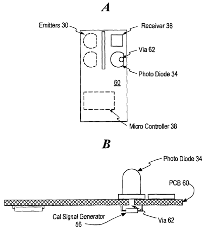
is preferably disposed on a single circuit board 60, as
shown in Figs. 6A and 6B, along with the other svstem
elements. In order to make the monitoring system as
unobtrusive as possible in a vehicle application, it is
preferred to densely pack the elements on the circuit board
60, the latter having plural conductive and insulating
layers. This enables the circuit board 60 to have circuitry
on both sides, as shown in Fig. 6B. In one embodiment, the
CA 02390584 2002-05-08
WO 01/36772 PCT/US00/21510
-16-
receiver and photodiode 34 are disposed on a side of the
circuit board 60 opposite the bulk of the remaining
circuitry, including the calibration LED 56. This
facilitates electromagnetic isolation of the receiver,
leading to improved system performance.
The reference LED 56 is separately controlled with
respect to the IR LEDs 30. A small aperture such as a
plated via 62 through the printed circuit board is provided
between the calibration LED 56 (also referred to as the
reference LED) and the photodiode 34 in the receiver portion
of the monitoring system. The calibration LED 56 is
preferably chosen with temperature response characteristics
similar to those of the IR LEDs 30; it is possible to
account for the temperature response of the IR LEDs 30
through the normal calibration process prior to each use of
the monitoring system.
A further advantage of employing a calibration LED 56
and IR LEDs 30 having a common temperature response curve
which is inverse to that of the receiver 36 is that at least
a portion of the temperature-dependent variation in receiver
performance is automatically offset by the decrease in LED
efficiency with increased temperature. This results in a
reduction in the overall loop gain necessary to keep the
monitoring system at a stable operating point.
Experimental results indicate that a 30ms to 40ms
output pulse is the optimum value for output pulse widths
from the receiver, though higher or lower periods are used
in alternative embodiments. It is therefore desired to have
the receiver output be in this range in the absence of an
obstacle in or proximate the aperture being monitored. This
is achieved by activating the calibration LED 56, whose
radiation impinges upon the photodiode 34 of the photo IC 32
CA 02390584 2002-05-08
WO 01/36772 PCT/US00/21510
-17-
in the receiver section of the system, then adjusting the
receiver gain by the controller 38 to produce a desired
output pulse width. The calibration LED 56 drive current is
used to determine the proper drive current for the IR LEDs
30, which should then produce the same receiver output in
the absence of obstacles. This is because a previously
performed calibration step correlates the drive current for
the calibration LED 56 with the drive current for the IR
LEDs 30 such that both produce the same output from the
monitoring system receiver 36, the calibration LED 56 by
emitting radiation through the via 62 in the circuit board
60, and the IR LEDs 30 through emitting radiation adjacent
and/or within the respective aperture and causing a given
amount of radiation to be reflected back to the photodiode
34. In one embodiment, the calibration LED 56 is activated
for this purpose for approximately lOmS.
In contrast to the foregoing non-contact system, a
contact-based system detects a change in the operating
characteristics of the closure, such as a window, during a
close operation. Such systems include time-based systems
and motor characteristic-based systems.
With reference to Fig. 7, a time-based obstacle
detection system 100 relies upon a predetermined acceptable
range of times for a closure to reach a fully closed
position within an aperture, or to reach some intermediate
position in the aperture. A controller 102, such as a
programmable microprocessor, is in communication with a
source of timing data such as a local oscillator 104. The
local oscillator may be replaced by an external timing
signal from another system. Also associated with the
controller is a memory 106 which retains data pertaining to
the length of time an obstruction-free closure 108 would
CA 02390584 2002-05-08
WO 01/36772 PCT/US00/21510
-18-
take to move a given distance, or to move from one position
in the aperture 110 to another. Alternatively, a range of
acceptable times is provided in the memory. The same memory
element may also be used to store the closure position
relative to the aperture at any given instant; this
information may be used to recover window position once
power is restored following a power interrupt. The
controller would simply write the derived position
information to the memory on a periodic basis. This feature
is particularly useful if the closure was in a partially
open state at the time of the power interrupt.
The controller 102 is also in communication with a
motor 112. The motor 112 is in mechanical communication
with the closure 108 through one of a variety of mechanical
arrangements as well known to one skilled in the art.
Typically, a linear relationship exists between the number
of motor drive shaft rotations and the linear displacement
of the associated closure. Likewise, there is typically a
linear relationship between the motor rotational rate and
the rate of motion of the closure. Given these
relationships, the controller 102 can infer the closure 108
position within the aperture 110 in a variety of ways once a
start position (such as a fully retracted position) is
known. The controller 102 can further establish whether the
closure is in the right location in the aperture 110 at the
right time, or alternatively if the closure 108 is
travelling at the correct range of speeds. Further still,
another embodiment of such a system may confirm whether the
closure motor speed has the proper rate of change as the
closure is moved.
In order to establish whether the closure 108 is in
certain critical locations in the aperture 110 at a given
CA 02390584 2002-05-08
WO 01136772 PCT/US00/21510
-19-
time, some means 114 must be provided in association with
the closure to establish relative position. These means 112
may include: an optical sensor operating in conjunction with
some form of encoded symbology disposed on the closure 108
or in conjunction with a tab for interrupting a light beam
emitted and detected by the optical sensor; a sensor
responsive to a plurality of elements disposed in
conjunction with the closure, each such element having a
unique characteristic such that closure position may be
inferred by determining where the series of elements are
located relative to the sensor; a plurality of sensors
disposed proximate the aperture and the closure path of
travel for detecting one or more elements disposed in
conjunction with the closure; or other such arrangements.
The sensor may be optical, magnetic, or mechanical, with the
appropriate type of cooperating element being disposed in
association with the closure. Alternatively, a mechanical
sensor or series of sensors may be employed in the aperture
110 which are capable of detecting the closure 108 without
the need for additional signaling elements on the closure
108 itself. Further, sensing elements may be disposed on
the closure, with the cooperating elements to be sensed
disposed in conjunction with the aperture 110, adjacent the
travel path of the closure 108. In the latter case, the
cooperating elements may be active, such as magnets for a
magnetic sensor, or passive, such as indicia to be scanned
by an optical scanner.
Closure position information is employed by the
controller 102 in order to determine if the closure 108 is
in the correct position, or range of positions, at the right
time, or range of times. These ranges may be established
through empirical analysis of closure function over a range
CA 02390584 2002-05-08
WO 01/36772 PCT/US00/21510
-20-
of operating environments in which the closure system may be
disposed.
A further contact-based system may avoid the need for a
discrete sensor and detectable elements by monitoring the
motor 112 which drives the closure 108 in the aperture 110.
In this embodiment, some characteristic of the motor 112 is
monitored in order to gauge the operation of the closure
108. The motor 112 current typically exhibits periodic
fluctuations in conjunction with the rotation of the motor
drive shaft. In one embodiment, the motor drive current may
be monitored by inserting a resistor 120 in series with the
motor supply, then sending the detected potential through an
AC amplifier 122 with a specific predetermined frequency
response. The amplifier 122 output is converted into a
square wave by a converter circuit 124 as known to one
skilled in the art. A counter 126 is then used to count the
number of pulses in the motor supply current. This count,
also referred to as a ripple count, is used as a measure of
the distance the closure 108 has traveled. The frequency of
occurrence of these pulses is used as a measure of the motor
speed.
One potential drawback with a ripple count circuit is
the potential need to adapt the controller 102 if the motor
112 is replaced, as each motor has its own characteristic
periodic fluctuation. Thus, one motor 112 may have periodic
signals from which a square wave or ripple may be extracted,
while a replacement motor 112 may have a more complex
periodic waveform. To address this situation, a further
embodiment of a contact-based system employs metrics derived
more generally from the periodic nature of the motor
current, without requiring that the motor signal be
converted to a square wave. For instance, if the spectral
CA 02390584 2002-05-08
WO 01/36772 PCT/US00/21510
-21-
density function associated with the motor current is
derived then the mean frequency can be monitored as a
measure of closure speed. In a similar fashion the
autocorrelation function associated with the motor current
may be derived. Alternatively, in a simple implementation,
the frequency content may be assessed by monitoring the
energy passed by one or more frequency selective filters.
The measurement of the impeding force experienced by
the closure can be detected as an unexpected decrease in
closure velocity as revealed by a corresponding decrease in
the required components. For instance, a measured rate
which deviates from an expected rate by a small percentage
may be interpreted as an accumulation of ice or dirt on the
closure, whereas a larger deviation may be interpreted as
the detection of an obstacle. The establishment of
acceptable ranges and the rules which define the
interpretation of the measured data are achieved based on
the expected environment in which the aperture and closure
are to be located and the empirical response by the closure
system to a variety of test conditions, including the
insertion of test obstacles.
In order to supplement the ability of a contact-based
system to detect an obstacle, or to provide an indication
that an obstacle is more likely than not,-a measure of the
motor drive current may be employed through the use of a
current detection circuit 130. The specific implementation
of this circuit 130 may be as known to one skilled in the
art. Thus, if the pulse counter 126 indicates that the
closure 108 reached a certain position in the aperture at a
time outside an acceptable range, but the monitored motor
current was within a normal range during the closure travel,
it may be inferred that the motor itself has degraded and is
CA 02390584 2002-05-08
WO 01/36772 PCT/US00/21510
-22-
now unable to raise the closure in the target time range.
In a further embodiment of a contact-based system as
disclosed, the range of acceptable times is shifted in order
to compensate for a slowing trend in motor function. Also
to be considered in a system which updates the acceptable
ranges are a number of past measurements as stored in memory
106 associated with the controller 106. Thus, if a given
number of previous measurements have exhibited a similar
shift in performance, this may be cause for redefining the
acceptable range of counter values or closure travel rates.
The more factors characterizing closure behavior that
are considered, the better the opportunity for accurately
discriminating the presence of an obstacle from aberrant
behavior of the closure system absent an obstacle.
Therefore, the use cf detected DC motor current in
conjunction with the measurements taken with respect to the
distance traveled by the closure or the rate at which the
closure traveled for a given period yields a more reliable
interpretation of closure function, when only a contact
based system is used.
However, a contact-based system must still rely upon
the actual entrapment of an obstacle in order to initiate
corrective procedures. As previously acknowledged, it is
preferable to provide a system which enables the detection
of obstacles without the need for entrapment first. Yet,
non-contact systems may suffer from degraded sensitivity in
the terminal portion of the closure travel path within the
aperture, potentially depending upon the location of the
sensor system in relation to the aperture and closure and
upon the physical configuration of the aperture and closure
themselves. Non-contact systems also may not provide a high
CA 02390584 2002-05-08
WO 01/36772 PCT/US00/21510
-23-
degree of confidence in the belief that a closure has
reached a terminal position within the aperture.
Thus, a more accurate obstacle detection system is
realized through the use of both contact and non-contact
obstacle detection systems. Such a hybrid system is
illustrated in block diagram form in Fig. 9, where the non-
contact system may include the emitter/detector module 14 of
Figs. 1-6B and the contact-based system may include one of
the detector arrangements described in conjunction with the
system 100 of Fig. 7. In an alternative embodiment, the
non-contact system includes an ultrasound, or ultrasonic,
emitter/detector, as known in the prior art. The ultrasound
emitter/detector module may be located at the same or a
similar position proximate the respective aperture as that
for the IR emitter/detector module. The non-contact system
avoids entrapment of an obstacle in the detection process,
while the contact-based system provides an accurate
indication of closure relative position as well as
supplemental obstacle detection at closure positions for
which the non-contact system sensitivity is less than
optimal.
The controller employed in the hybrid system of Fig. 9
may be the controller 102 used in conjunction with the
contact-based system of Fig. 7, the controller 38 of the
non-contact system of Fig. 3, a dedicated controller 202
working in conjunction with the first two controllers 38,
102, or a processing element already found in the aperture
environment and adapted for use in controlling such a hybrid
system. For instance, in a vehicle aperture embodiment, an
electronics module which communicates over a vehicle
communications bus may be adapted for this purpose.
Communications between the elements of the presently
CA 02390584 2002-05-08
WO 01/36772 PCT/US00/21510
-24-
disclosed hybrid system, including the one or more
controllers, is preferably through standard communications
pathways or buses. Such pathways may be electrically
conductive or optical.
The degree to which the sensitivity of a non-contact
system varies is most likely dependent on closure position
and/or obstacle position within the aperture. These factors
can then be used to define the point at which factors from a
contact-based system are considered or are emphasized in
making a determination of whether an obstacle is present.
For instance, testing with a variety of obstacles may
indicate that a non-contact system such as one employing an
IR emitter and associated detector is extremely sensitive
over the lower 750 of an aperture. Thus, over this portion
of the aperture, the controller 102 may rely solely on the
output from the detector portion of the non-contact system,
such as that shown in Figs. 1-6B. An indication of closure
position may be provided as an input from the contact-based
system 100. Additionally, closure position may be inferred
as a result of detection by the non-contact system 14. For
instance, a characteristic change may be observable in the
non-contact system output when the closure reaches a certain
position within the aperture.
As the closure 12 is driven into the final 250 of its
travel path within the aperture 20 in this example, input
from the contact-based system may be utilized in conjunction
with the non-contact system information in determining
whether an obstacle is present. In this example, the final
250 of the travel path may be defined as the "pinch zone."
Thus, as in Fig. 9, a common controller or processing
element 200 receives inputs from both systems and, depending
CA 02390584 2002-05-08
WO 01/36772 PCT/US00/21510
-25-
upon closure position, relies on one or both for obstacle
detection.
Assume the aperture has nearly reached the top of its
travel path. The non-contact system receiver output is
within the normal range. However, the contact-based system
indicates that the closure motor is rotating at a rate below
a previously established minimum threshold. The controller
may be programmed to interpret this data in a variety of
ways. If the deviation in motor speed is slight, prior
empirical analysis may suggest that the closure motor is
exhibiting temperature related effects, or that the closure
itself may be fouled with ice or debris. A temperature
indicating device may be utilized as a further input to
confirm or rule out such an option. If the deviation in
motor speed is significant, it may be established that an
obstacle is present, one which was not detected by the non-
contact system. In the latter case, appropriate action is
invoked to free the perceived obstacle, including the
reversal of closure travel direction and/or the activation
of an alarm.
Alternatively, the motor driving the closure may be
slowed subsequent to an initial, preliminary indication from
the non-contact system that an obstacle may be present. In
this embodiment, different tolerances for the sensor
thresholds (contact and/or non-contact) may be applied in
order to make a more accurate determination of whether an
obstacle is indeed present. If so, the corrective action
referred to above is invoked.
Another advantage of employing dual systems for
obstacle detection is evident when the non-contact system
receives returned energy which is beyond a threshold level
(either above or below, depending upon the specific
CA 02390584 2002-05-08
WO 01/36772 PCT/US00/21510
-2 6-
embodiment of the non-contact system). By referencing the
contact-based system, it is possible to determine if the
non-contact system's result is indeed indicative of an
obstacle or of a change in the performance of the non
contact system which must be accounted for.
If it is established through the contact-based system
that no obstacle is present, the combined system can be
provided with the capacity to dynamically adjust to
variations in the background-reflected radiation. This can
be achieved in a number of ways. The detected energy level
may be averaged with the difference between each of a
selected number of previously detected energy levels and the
threshold, as stored in memory associated with the system.
The result of this averaging process is utilized in defining
an offset for the non-contact system for future cycles. For
instance, an offset can be defined for the emitter, or for
the receiver gain. This offset can cause an adjustment in
the difference between the threshold value and the receiver
output by a percentage of the averaged variations. The
number of samples from the previous measurements to be
averaged can be varied depending upon the rate at which
background-reflected radiation is expected to change as a
result of predicted surface degradation, or based upon an
empirical analysis by the system of the rate of change of
background-reflected radiation. Alternatively, the
difference between the current receiver output and the
threshold may be used without previous measurements in
defining an appropriate offset. Still further, a desired
number of discontinuous prior measurements is utilized in an
averaging process.
In a further embodiment of the present hybrid system,
the controller 202 may have associated with it a memory 204
CA 02390584 2002-05-08
WO 01/36772 PCT/US00/21510
-27-
for storing threshold values for both the non-contact and
contact systems, for storing the appropriate actions to be
taken depending upon which thresholds are achieved, and for
storing empirical data reflective of previous measurements
from the non-contact and contact systems. Thus, if the non-
contact system fails to register an object and the contact-
based system registers a motor rotation rate slightly below
a pre-established threshold, the controller may reference
the most recently stored performance data for the closure to
determine if a trend towards slower motor rotation rate can
be established. If so, the relevant thresholds for the
motor rotation rate can be adjusted accordingly for future
reference.
In a further embodiment, the memory element may be used
to store an acceptable speed pattern as a function of
closure position should this not be a constant value. This
might be necessary if for example extra force is required to
bring the closure to a fully closed position where a gasket
seal is required.
If the non-contact system has once again failed to
register an obstacle, but the contact-based system has
exhibited a significantly slower motor rotation rate or a
closure position which is short of the fully closed position
within the aperture, an obstacle detection may be
recognized, and the thresholds for the non-contact system
may be adjusted incrementally in order to increase the
sensitivity of the non-contact system.
Alternatively, the contact-based system may be
considered in conjunction with the non-contact system over
the entire range of closure travel. The controller may then
employ multiple factors in establishing the presence of an
obstacle. These factors may include the level of reflected
CA 02390584 2002-05-08
WO 01/36772 PCT/US00/21510
-28-
energy or the time at which energy was received relative to
the time it was emitted, both factors coming from the non-
contact system. Additionally, the controller may employ one
or more of the motor rotation speed (and thus the closure
travel rate), the closure absolute position, and the rate of
change in the closure travel rate, all coming from the
contact-based system.
Thus, the controller 202 according to the present
disclosure operates in conjunction with a knowledge base
adapted to classify a variety of contact and non-contact
system inputs for the purpose of identifying an obstructed
closure within an aperture, such identification resulting in
the initiation of corrective action. Among the possible
inputs from a contact-based system are motor shaft rotation
rate or frequency, motor current, closure position, and
duration of closure movement. Closure position in this
context means the relative position of the closure within
the aperture as well as whether the closure has reached a
"fully closed" position. Among the possible inputs from a
non-contact system are the degree to which a received amount
of energy varies from an expected amount (i.e. either
exceeds an expected amount or falls short of an expected
amount, depending on the embodiment) and a shift in the time
taken for the emitted energy to return to a receiver for
some percentage of the total received energy.
Preferably, the controller 202 is capable of providing
an output, through appropriate interface circuitry, which
results in the stoppage of a closure for a respective
aperture when the controller 202 determines that an
obstruction is present. The closure may be commanded to
reverse its motion and move to the fully open position. In
addition, the controller 202 may provide an output
CA 02390584 2002-05-08
WO 01/36772 PCTNS00/21510
-29-
indicative of threshold achievement for the purpose of
initiating some form of aural or visual alarm.
These and other examples of the invention illustrated
above are intended by way of example and the actual scope of
the invention is to be limited solely by the scope and
spirit of the following claims.