Note: Descriptions are shown in the official language in which they were submitted.
CA 02390611 2002-06-13
CONCRETE FINISHING APPARATUS
CROSS REFERENCE TO RELATED APPLICATION
The present application claims priority on U.S. provisional application, Ser.
No.
60/298,054, filed June 13, 2001 by Somero et al. for CONCRETE FINISHING
APPARATUS (Attorney Docket SOMO1 P-312), which is hereby incorporated herein
by
reference in its entirety.
FIELD OF THE INVENTION
The present invention relates generally to a concrete finishing, smoothing
and/or
leveling apparatus and, more particularly, to a concrete smoothing and
leveling apparatus
1o which is operable on partially cured concrete to smooth the partially cured
concrete surface to
a flat, level surface.
BACKGROUND OF THE INVENTION
There is a growing need in the industry for close-tolerance, flat and level
concrete
floors for various buildings or structures, such as warehouses, manufacturing
facilities and
15 the like. Many manufacturing plants include high-precision equipment which
must be level
and thus benefit from having close-tolerance floors to allow for easier
initial installation, set
up and/or reorganization of the equipment. Additionally, high-density
warehouse facilities
often utilize narrow aisles and high-reach forklifts to reach tall storage
racks for shelving.
Any offset from level of the floor then corresponds to an offset from vertical
of the high-
2o reach forklift, which may result in difficulty in maneuvering the forklifts
along the aisles and
in reaching the upper shelves. Such warehouse facilities thus also benefit
from very smooth
and accurately level floors for efficient installation and use of equipment
and for stocking of
the shelves.
Close-tolerance floors are often referred to in the industry as "super-flat
floors" or
25 simply "super flats". Such super-flat floors are typically expensive for
concrete contractors to
produce, since such projects usually require specialized equipment and
experienced personnel
with a thorough knowledge of the process. Because of the high cost of the
super-flat floors,
often only specified areas of a building floor will be made to super-flat
specifications, such as
within anticipated aisleways of a given floor plan. However, the spacing or
location of the
3o aisles then cannot be easily adjusted later, which increases future
renovation costs and
possibly the future value and usefulness of the facility.
CA 02390611 2002-06-13
" 4
Close-tolerance, super-flat concrete floors are specified, measured and
compared in
the concrete industry according to concrete floor profile specification
variables. One of these
variables is for floor flatness "F-F" and another is for floor levelness "F-
L". These two
specifications together are generally referred to in the industry as F-
numbers. The F-number
system offers a repeatable method for measuring floor quality through
statistical means
known in the art. Concrete floors having F-numbers near or above the range of
F-F 80 and F-
L 80 are typically regarded as being super-flat concrete floors.
Super-flat concrete floors are much more difficult and expensive to achieve
than those
conventionally poured. In order to achieve such super-flat floors,
construction work site
personnel must be highly trained and skilled, and special equipment is often
required to place
and finish the concrete. Striking-off wet, uncured concrete to a specified
grade for a
conventional floor can be performed using hand tools. However, a large number
of workers
are required to finish the floor, and production speed of the floor is thus
relatively slow with
such conventional processes. Additionally, as an operator continues to work
with the manual
~5 devices, such as trowels and scrapers, for a long period of time, the
operator will tire as the
day goes on, which will have an adverse affect on the final F-numbers and
quality of the
floor. Therefore, because many flat floors are finished by manual labor, the
floors are likely
to have relatively poor accuracy in the overall surface levelness and
flatness.
In many applications, the use of a laser screeding device, such as the Somero
Laser
Screed, developed by Somero Enterprises of Houghton, Mich., is often required
when the
goal of a super-flat floor is to be achieved. Other special application tools
and equipment,
such as highway straight edges, power trowels, pan machines and double
trowels, may be
used separately, at the same time, or in combination with one another, during
the finishing
process. Because a significant amount of time and effort of experienced and
skilled workers
and special equipment and/or machinery is required to achieve a super-flat
floor quality,
achieving such a floor is often a relatively expensive and time consuming
process.
Many concrete processing applications have implemented a spinning tube, or the
like,
in constructing a concrete floor or surface. However, such spinning tube
applications are
implemented as an initial strike-off tool or screed for striking-off or
screeding freshly placed
and uncured concrete to the desired grade. These tube type roller screeds are
necessarily
supported on some type of preset forms or screed rails to maintain grade
height. Because
these screeding devices are applicable only to freshly poured, uncured
concrete,
implementation of such devices does not result in a close-tolerance or super-
flat concrete
floor surface. The additional manual processes still have to be performed on
the surface after
-2-
t . CA 02390611 2002-06-13
the initial screeding operation is completed, and after the concrete is at
least partially cured
and set up, in order to obtain such a super-flat, high quality, floor surface.
Therefore, there is a need in the art for a concrete smoothing and leveling
apparatus
which is capable of finishing a concrete surface to a super-flat or close-
tolerance finish. The
apparatus should require minimal manual labor processes and be inexpensive to
operate over
the entire floor surface.
SUMMARY OF THE INVENTION
The present invention is intended to provide a concrete floor or surface
finishing
apparatus which is operable to finish a surface of a partially cured concrete
slab to a super-
flat, smooth and level floor surface. The apparatus of the present invention
requires minimal
manual labor processes to achieve the desired floor surface quality.
Additionally, the
apparatus of the present invention is applicable to large floor surface areas,
whereby the
entire floor surface can achieve the desired super-flat and level floor
qualities.
According to a first aspect of the present invention, a concrete finishing
apparatus for
smoothing and leveling partially cured concrete at a support surface includes
a movable unit
and at least one rotatable finishing member mounted at the movable unit. The
movable unit
is movable and supported over and/or on the partially cured concrete and is
movable in at
least a first direction. The at least one rotatable finishing member is an
elongated cylindrical
member, such as a cylindrical tube, roller, cylinder or the like. The
rotatable finishing
2o member includes a longitudinal axis and is rotatable about the longitudinal
axis. The
rotatable finishing member defines a cylindrical contact surface therealong
which is adapted
to contact a surface of the partially cured concrete as the rotatable
finishing member is rotated
over the partially cured concrete. The finishing member is rotatable such that
the contact
surface moves relative to the surface of the partially cured concrete as the
movable unit and
the rotatable finishing member are moved over the partially cured concrete.
Preferably, the rotatable finishing member is positioned behind the movable
unit as
the movable unit moves in the first direction. The finishing member is
rotatable in an
opposite direction from the first direction such that the contact surface is
movable relative to
the partially cured concrete surface in the first direction as the movable
unit moves in the first
3o direction.
In one form, the rotatable finishing member is vertically adjustable.
Optionally, the
concrete finishing apparatus may include a laser leveling system. The
rotatable finishing
member is then vertically adjustable in response to the laser leveling system.
The rotatable
finishing member may also or otherwise be variably weighted to adjust or vary
an amount of
-3-
1 ~ CA 02390611 2002-06-13
force or downward pressure being applied to the partially cured concrete by
the rotatable
finishing member.
The movable unit of the concrete finishing apparatus includes at least one
support
which spreads the weight of the movable unit over an area of the partially
cured concrete to
limit depression of the partially cured concrete by the movable unit. In one
form, the at least
one support includes at least four inflatable tires. In another form, the at
least one support
includes at least two elongated rollers which are rotatable to move the
movable unit over the
concrete surface. In yet another form, the at least one support includes at
least two
continuous tracks.
to Alternately, the movable unit may include only one tire, wheel or roller,
or two
generally coaxial tires, wheels or rollers, such that the rotatable finishing
member is
substantially supported on the partially cured concrete surface due to the
weight of the
finishing member. Alternately, the movable unit may include an air cushion
unit which is
operable to be supported above the concrete surface via a cushion of air
generated by the air
15 cushion unit. It is further envisioned that the movable unit may be a power
trowel or riding
trowel apparatus, with the rotatable finishing member mounted at a rearward
end of the
power trowel, without affecting the scope of the present invention.
The concrete finishing apparatus of the present invention may include two
rotatable
finishing members positioned at opposite ends of the movable unit. One of the
two rotatable
20 finishing members then may be lowered to contact and smooth the partially
cured concrete
surface when the movable unit is moved in the first direction, while the other
of the two
rotatable finishing members is lowered to contact and smooth the partially
cured concrete
surface when the movable unit is moved in a second direction. The second
direction is
generally opposite the first direction. Optionally, both rotatable finishing
members may be
25 lowered to engage and finish the partially cured concrete surface as the
movable unit moves
over and along the partially cured concrete surface.
The rotatable finishing member of the concrete finishing apparatus may be
positioned
relative to the movable unit such that the longitudinal axis of the rotatable
finishing member
is generally normal to the first direction. Alternately, the rotatable
finishing member may be
3o positioned relative to the movable unit such that the longitudinal axis of
the finishing member
is skewed or canted relative to the first direction, i.e., positioned at an
angle to the first
direction. Preferably, the orientation of the finishing member relative to the
movable unit is
adjustable in order to change the skew or angle of the rotatable finishing
member depending
on the application.
-4-
~1 ~ CA 02390611 2002-06-13
According to another aspect of the present invention, a method for finishing a
concrete surface of partially cured concrete includes providing a concrete
finishing apparatus
having a movable support and a rotatable finishing member. The movable support
and
rotatable finishing member are moved over and/or on the concrete surface such
that the
movable support is supported on and/or over the partially cured concrete. The
rotatable
finishing member defines a generally cylindrical contact surface for
contacting the concrete
surface and is positioned at the concrete surface. The rotatable finishing
member is rotated
about a longitudinal axis of the finishing member to move the contact surface
relative to the
partially cured concrete surface as the movable support and the rotatable
finishing member
1 o move over the concrete surface.
In one form, the method includes moving the movable support and the rotatable
finishing member in a first direction. The method may further include rotating
the rotatable
finishing member to move the contact surface in the first direction. The
method may also
include positioning the rotatable finishing member behind the movable support
as the
15 movable support moves in the first direction.
During operation, the rotatable finishing member is preferably positioned and
pulled
behind the movable unit as the movable unit moves in the first direction. The
rotatable
finishing member is then rotatable in a generally opposite direction from the
first direction,
such that the contact surface is movable relative to the concrete surface in
the first direction
20 as the movable unit moves in the first direction. The rotational speed of
the finishing
member is selected such that the finishing member contact surface generates
sufficient
slippage over the partially cured concrete to smooth the concrete to a high
quality finish.
The movable support may be ridden and driven by an operator, or manually moved
over the partially cured concrete surface by an operator walking on the
surface, or may be
25 remotely controlled by a remote control device or programmable to move and
finish the
partially cured concrete surface in a programmed manner.
Therefore, the present invention provides a concrete smoothing and finishing
apparatus and method for smoothing partially cured concrete at a support
surface to a super-
flat, high quality finish. The apparatus is operable to provide a smooth
finish over a large
30 area and requires minimal manual processes. Accordingly, the present
invention provides a
more efficient and effective smoothing and finishing apparatus and method for
achieving
high quality, super-flat and level floor surfaces. In addition, the machine
and process method
of the present invention may also serve to significantly shorten the cure
cycle time of the
finished concrete surface such that in the overall perspective, less time,
effort, and cost may
-5-
t ~ CA 02390611 2002-06-13
be incurred by the construction contractor, while at the same time, improving
the overall
quality of the finished concrete surface.
These and other objects, advantages, purposes and features of this invention
will
become apparent upon review of the following specification in conjunction with
the
drawings.
BRIEF DESCRIPTION OF THE DRAWINGS
FIG. 1 is a perspective view of a concrete finishing apparatus in accordance
with the
present invention having a four-wheeled movable unit and having the rotatable
finishing
members skewed at an angle relative to the longitudinal axis and direction of
motion of the
to movable unit;
FIG. 2 is a side elevation of the concrete finishing apparatus of FIG. 1;
FIG. 3 is another perspective view of the concrete finishing apparatus of
FIGS. 1 and
2, with the rotatable finishing members positioned generally normal to the
longitudinal axis
and direction of motion of the movable unit;
FIG. 4 is another side elevation of the concrete finishing apparatus of FIGS.
1-3, with
the rotatable finishing members in the orientation of FIG. 3;
FIG. 5 is a perspective view similar to FIG. 3, with the seat removed from the
concrete finishing apparatus and including an optional concrete cream scoop
and end-wing
plow;
2o FIG. 6 is an upper perspective view of a wheeled base unit useful with the
present
invention;
FIG. 7 is a lower perspective view of the wheeled base unit of FIG. 6;
FIG. 8 is a lower perspective view of a roller base unit useful with the
present
invention;
FIG. 9 is a perspective view of a three-wheeled concrete finishing apparatus
having a
single rotatable finishing member in accordance with the present invention;
FIG. 10 is a rear perspective view of the three-wheeled concrete finishing
apparatus of
FIG. 9;
FIG. 11 is a perspective view of an alternate embodiment of a concrete
finishing
3o apparatus in accordance with the present invention having an air cushion
movable unit;
FIG. 12 is a side elevation of the concrete finishing apparatus of FIG. 11;
FIG. 13 is a perspective view of another alternate embodiment of a concrete
finishing
apparatus in accordance with the present invention having a movable unit
supported and
movable by a pair of continuous tracks at either side of the movable unit; and
-6-
'T , CA 02390611 2002-06-13
FIG. 14 is a perspective view of another alternate embodiment of a concrete
finishing
apparatus in accordance with the present invention having a rotatable
finishing member
mounted to a rearward end of a power trowel.
DESCRIPTION OF THE PREFERRED EMBODIMENTS
Referring now specifically to the drawings and the illustrative embodiments
depicted
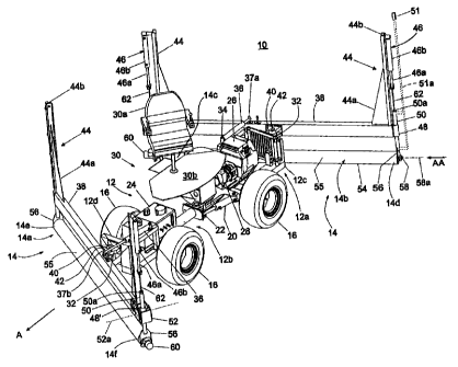
therein, a roller leveler concrete finishing apparatus or machine 10 includes
a movable unit or
support 12 and one or more rotatable, generally cylindrical finishing members
14, such as a
pair of rotatable finishing members 14a, 14b, such as rollers, tubes or
cylinders or the like, at
opposite ends of the movable unit 12 (FIGS. 1-5). Movable unit 12 is movable
over and
1o supported on partially cured concrete, while at least one of the rotatable
finishing members
14a, 14b contacts a surface of the partially cured concrete and rotates or
spins over the
concrete surface. The spinning finishing members 14 thus slip relative to the
surface of the
partially cured concrete to remove a thin layer of cement paste from the
partially cured
concrete surface to provide a high quality, smooth, flat and level surface. As
movable unit 12
15 is moved in one direction, a rearward one of the rotatable finishing
members is lowered such
that the rotatable finishing member is in generally constant contact with the
surface of the
partially cured concrete. The rotatable finishing member is spun in a
direction that is
generally opposite to the direction of travel of the machine, such that the
thin layer of cement
paste removed by the finishing member is carried to a forward side of the
finishing member,
2o just ahead of the spinning finishing member. This allows the excess cement
paste to drop off
and fill in any low areas or depressions, or any area that is otherwise below
the desired grade,
as the spinning finishing member moves over such areas. Concrete finishing
machine or
apparatus 10 thus provides a close-tolerance, super-flat concrete floor
surface as it is driven
over the partially cured concrete, as discussed in detail below.
25 In the illustrated embodiment of FIGS. 1-5, movable unit 12 is an
articulated-wheeled
vehicle having four wheels 16 for driving and supporting the movable unit over
the partially
cured concrete surface. The wheels may be independently drivable via hydraulic
motors (not
shown) or the like or may be chain driven or driven via any other drive means,
without
affecting the scope of the present invention. Preferably, wheels 16 of movable
unit 12
3o include wide and smooth tires, such as balloon type tires or the like,
which provide a larger
contact surface or footprint on the surface of the partially cured concrete to
limit depression
or sinking of movable unit 12 into the partially cured concrete surface.
Movable unit or wheeled vehicle 12 is steerable via articulation of the unit
about a
generally central, generally vertically oriented, pivot axis 18 (FIGS. 2 and
4). An actuator or
_7_
CA 02390611 2002-06-13
hydraulic cylinder 20 is preferably mounted on one portion, such as a rear
portion 12a of
movable unit 12, and is connected to a lever arm or moment arm 22 of the other
portion, such
as front portion 12b, of movable unit 12. Accordingly, extension and
retraction of hydraulic
cylinder 20 causes the front portion 12b to pivot about pivot axis 18 relative
to rear portion
12a to steer the movable unit 12 as it is driven along the partially cured
concrete surface.
Preferably, movable unit 12 includes an hydraulic reservoir 24 and engine 26
which
powers an hydraulic pump 28 to provide pressurized fluid to the various
hydraulic cylinders
and hydraulic motors associated with concrete finishing apparatus 10, as
discussed below.
However, other driving means may be implemented, such as electrical devices or
the like,
l0 without affecting the scope of the present invention.
As seen in FIGS. 1-4, movable unit 12 may include an operator station 30 for
an
operator to sit at and drive and control finishing apparatus 10. The operator
station 30 may
include a seat 30a and a platform 30b and manual controls for operating the
concrete
finishing apparatus. The platform 30b and seat 30a may be pivotally mounted to
the movable
15 unit, such as to the rear portion 12a of movable unit 12, via a rotatable
turntable 30c (FIGS. 2
and 4) or the like, in order to allow the operator to turn the seat and
platform so the operator
is facing in the direction of travel of the movable unit. Alternately, as
shown in FIG. S, a
concrete finishing apparatus 10' may include a movable unit 12' which does not
include a
place for a driver to sit or ride on, and may otherwise be controlled via
remote control.
20 Optionally, the concrete finishing apparatus may be programmable to perform
the finishing
processes in a controlled, programmed manner, without affecting the scope of
the present
invention.
Movable unit 12 includes a roller mounting bracket or mount 32 extending
outwardly
from both a rear end 12c and a front end 12d of movable unit 12 for mounting
the rotatable
25 finishing members or rollers 14a, 14b to the movable unit 12, as discussed
in detail below.
Additionally, a bracket or mount 34 is provided at or near each end of movable
unit 12 for
mounting an actuator or hydraulic cylinder 36 thereto. The hydraulic cylinder
or cylinders 36
are operable to pivot or adjust the orientation of the rotatable finishing
members 14a, 14b
relative to movable unit 12, as also discussed below.
3o As best shown in FIGS. 1 and 3, a roller support or beam 38 is pivotally
mounted to
mounts 32 at each end of movable unit 12 via a mounting bracket 40 and a
generally
vertically oriented connecting pin or axle 42 or the like. Roller support
beams 38 are
elongated beams extending laterally outward from the generally centrally
positioned bracket
40 and function to provide support at either end of the rotatable finishing
members 14a, 14b.
_g_
CA 02390611 2002-06-13
Each of the hydraulic cylinders 36 is connected to a respective beam 38 at a
position which is
laterally offset from bracket 40, such as at one of the mounting positions 37a
or 37b, such
that extension and retraction of cylinder 36 causes pivotable movement of beam
38 about a
vertical axis 42a (FIGS. 2 and 4) defined by pivot pin or axle 42. This allows
the orientation
of the rotatable finishing members 14a, 14b to be adjusted relative to the
direction of travel of
movable unit 12, as discussed below.
Roller support beam 38 further includes a pair of generally vertical supports
or
brackets 44 extending generally upwardly from opposite ends of beam 38. Each
support 44
may further be supported by a gusset 44a or the like to limit deflection or
lateral movement of
to support 44. An actuator or hydraulic cylinder 46 is mounted at or near an
upper end 44b of
each support 44 and connected to a respective end of the corresponding
rotatable finishing
member 14a, 14b. Each hydraulic cylinder 46 is positioned generally vertically
along its
respective vertical support 44 and is operable to raise and lower a respective
end of rotatable
finishing member 14a, I 4b via retraction and extension of the hydraulic
cylinder 46.
A generally cylindrical collar or bushing 48 or 48' is mounted at each end of
beam 38
and receives and guides a generally cylindrical rod or post 50 of rotatable
finishing member
14a or 14b. Optionally, as shown at one end of the beams 38 in FIGS. 1 and 3,
one or both
collars 48' at one or both of the ends of each beam 38 may be pivotally
mounted to the end of
the respective beam 38 via a mounting bracket 52. The mounting bracket 52
pivotally
2o receives collar 48' and allows collar 48' to pivot about a generally
horizontal axis 52a (FIG. 1)
to accommodate any angular orientation of the rotatable finishing member
relative to the
respective support beam and thus avoid potential binding of rod 50 within
collar 48'.
Alternately, or additionally, brackets 32 or 40 at movable unit 12 or beam 38,
respectively,
may provide a U joint type connection or the like to accommodate such angular
orientation,
without affecting the scope of the present invention.
Each of the rotatable finishing members 14a, 14b is an elongated cylinder, or
cylindrical tube or roller, having a cylindrical roller portion 55 and a shaft
portion or end 58.
A longitudinal axis of rotation 58a of cylindrical members 14a, 14b is defined
between and
along shaft portions 58. The cylindrical roller portion 55 is rotatable about
axis 58a and
3o defines a smooth generally cylindrical outer contact surface 54 for
contacting the partially
cured concrete surface and smoothing and leveling the surface to a close-
tolerance finish.
However, the contact surface of the finishing member may be textured, without
affecting the
scope of the present invention. The diameter of the cylindrical finishing
members may be
selected depending on the length of the members and/or on the particular
application of the
-9-
't ~ CA 02390611 2002-06-13
finishing apparatus. For example, the finishing members 14a, 14b may be
selected to be
approximately 12 feet in length with a diameter of approximately 12 inches.
However,
longer or shorter members having larger or smaller diameters may be
implemented depending
on the particular application, without affecting the scope of the present
invention.
Each end of the finishing members 14a, 14b is rotatably mounted to a mounting
plate
56 in a suitable bearing or bearing block which receives a shaft end 58 of the
member 14a,
14b therethrough and allows for rotation of the cylindrical roller portion 55
of members 14a,
14b relative to mounting plate 56 via the bushing or bearing or the like (not
shown). The
shaft ends 58 may be rotatably received in mounting plates 56 and rotate
relative thereto, or
1o the shaft ends may be fixedly mounted to mounting plates 56, whereby the
cylindrical roller
portion 55 of each finishing member 14a, 14b is rotatable relative to the
respective fixed shaft
ends 58, without affecting the scope of the present invention. An hydraulic
motor 60 or other
means for rotatably driving the finishing member is mounted at one of the
mounting plates 56
for each finishing member 14a, 14b and is operable to drive or rotate the
respective rotatable
15 finishing member 14a, 14b about its respective axis 58a, such as via
pressurized hydraulic
fluid from pump 28 and engine 26 of movable unit 12. Preferably, hydraulic
motors 60 are
operable in either direction, such that the finishing members may be rotated
in either
direction, depending on the direction of travel of the movable unit 12.
Although shown with
generally flat ends, the rotatable finishing members 14 preferably have
rounded ends to limit
20 or substantially preclude an edge of the rotatable finishing members from
cutting or digging
into the partially cured concrete surface, or otherwise leaving a ridge or
uneven junction
between adjacent passes of the rotatable finishing members.
A cylindrical rod or post 50 extends upwardly from each mounting plate 56 of
each
end of finishing members 14a, 14b and is received through the respective
collar 48, 48' at the
25 ends of the respective support beam 38. Cylindrical rod 50 is slidably
received within collar
48, 48', such that each end of each finishing member 14a, 14b is vertically
adjustable via
vertical sliding movement of rods 50 within collars 48, 48'. An upper end 50a
of each rod 50
is connected to a respective piston rod 46a of the respective hydraulic
cylinder 46 via a
connecting member or linkage 62. Preferably, the linkage 62 is a flexible
cable, chain or the
3o like, such that retraction of piston rod 46a into cylinder portion 46b
pulls upward on the
vertical rod 50 via linkage 62 to raise the respective end of the respective
finishing member
upward from the partially cured concrete surface, while the hydraulic cylinder
46 may also
lower the rod 50 down to a point where the respective rotatable finishing
member rests or is
at least partially supported on the partially cured concrete surface, whereby
the linkage 62
-10-
, ~~ ' CA 02390611 2002-06-13
may have slack to allow the respective rotatable finishing member to
substantially rest or
"float" on the partially cured concrete surface.
Optionally, the rotatable finishing members 14a, 14b may be generally hollow
and
may be filled or partially filled with water or the like to adjust the weight
and downward
pressure of the members on the partially cured concrete surface when they are
lowered to
float on the surface. In the illustrated embodiment, the rotatable finishing
members have a
variable weight of between approximately 100 pounds and approximately 250
pounds. The
amount of water added to the rotatable finishing members may be selected
depending on the
particular application, degree of curing of the partially cured concrete
surface, desired result
l0 or surface or the like. However, it is further envisioned that hydraulic
cylinders 46, or any
other raising and lowering devices, may be directly connected to the vertical
support rods 50,
or may be connected via a solid link or a spring or the like, such that the
raising and lowering
devices may be operable to directly apply greater or less down pressure at the
ends of the
rotatable finishing members, in order to effectively adjust the weight or
force or down
15 pressure of the rotatable finishing members at the partially cured concrete
surface, without
affecting the scope of the present invention. The weight or down pressure of
the finishing
member may be adjusted to a desired amount via extension and retraction of the
hydraulic
cylinders, depending on the application and degree of cure of the partially
cured concrete
being processed.
2o It is further envisioned that the height or vertical position of the
finishing member
may be adjustable in response to a laser leveling system or control, such as
disclosed in U.S.
Pat. No. 4,655,633, which is hereby incorporated herein by reference. In such
an application,
each of the rods or posts 50 may then include a laser receiver 51 (FIG. 1),
which may be
mounted at upper end SOa of vertical support rods SO or mounted to a rod or
mast 51 a (as
25 shown in phantom in FIG. 1) attached to and along rod 50. The hydraulic
cylinders 46 are
extendable and retractable to maintain the rotatable finishing member at the
appropriate level
with respect to a signal from a laser beacon projector (not shown). The laser
receivers 51
detect a reference plane generated by the projector, and the controls of
finishing apparatus 10
automatically adjust the hydraulic cylinders 46 accordingly, as disclosed in
U.S. Pat. No.
30 4,655,633.
Additionally, the rotational speed of the finishing members may be varied
depending
on the degree of cure of concrete and the speed of the movable unit, and
further depending on
the application and characteristics of the concrete being processed and the
desired results.
-11-
i '~ . CA 02390611 2002-06-13
For example, the rotational speed of the finishing members may be decreased
for so$er
concrete and increased for harder or more completely cured concrete.
During operation, movable unit 12 is driven directly onto the surface of the
partially
cured concrete, after the concrete has been allowed to partially set up or
cure to a semi-
s hardened state. The length of time before driving the finishing apparatus
onto the partially
cured concrete is variable depending on the application, environment, and/or
any other given
work site conditions which may affect the degree of cure of the concrete over
a given period
of time. Typically, concrete finishing apparatus 10 would be driven onto the
partially cured
concrete after the concrete has cured to the point where a first conventional
finishing
0 operation, such as a power trowel or the like, would normally begin. The
actual cure amount
of the concrete prior to smoothing the surface is thus variable and
subjective. Optionally, a
standardized surface contact pressure test to measure the capacity of the
concrete to support
the weight of a machine may be performed to determine a preferred amount of
setup or cure
of the partially cured concrete prior to driving or moving the finishing
apparatus 10 onto the
t5 partially cured concrete.
As movable unit 12 is driven in a first direction of travel, such as in a
forward
direction, or generally to the left or in the direction of arrow A in FIG. l,
the rearwardly
positioned rotatable finishing member 14b is lowered onto the partially cured
concrete
surface via extension of cylinders 46 until the contact surface 54 of
rotatable finishing
2o member 14b rests upon the partially cured concrete surface. The finishing
member may rest
or float upon, or may be pushed downwardly onto, the concrete surface with its
axis of
rotation 58a being generally parallel to the partially cured concrete surface.
Hydraulic motor
60 is actuated to rotate finishing member 14b about axis 58a to cause slippage
of the contact
surface 54 of rotatable finishing member 14b on the partially cured concrete
surface, in order
25 to smooth the surface to a highly smooth and flat quality. Preferably,
hydraulic motor 60 is
operable to rotate finishing member 14b in a direction opposite the direction
of travel of
movable unit 12. In other words, hydraulic motor 60 is preferably operable to
rotate finishing
member 14b in a clockwise direction, when viewed in the direction of arrow AA
in FIG. l,
when movable unit 12 is driven in the direction of arrow A. This causes a
lower engaging
3o portion of contact surface 54 of rotatable finishing member 14b to move or
slip relative to the
concrete surface in generally the same direction as movable unit 12, or in an
opposite
direction than it would move if rolling along the partially cured concrete
surface.
The slippage of finishing member 14b over the partially cured concrete surface
causes
a thin layer of cement paste to be removed by finishing member 14b. Because
the direction
-12-
CA 02390611 2002-06-13
of rotation is preferably opposite to the direction of travel, the cement
paste is carned
forwardly by the rotating finishing member 14b as the movable unit 12 is moved
across the
concrete surface. Also, because the cement paste is skimmed off the surface of
the concrete
and moved along by the rotatable finishing member, when the finishing member
reaches a
depression or an area below grade, some of the excess concrete paste will be
deposited in the
lower areas to enhance the level and flatness of the floor. The process of
removing the excess
cement paste from any high areas or other imperfections and depositing the
cement paste in
the lower areas results in a highly flat and level floor quality for the
concrete surface.
Preferably, finishing apparatus 10 further includes a roller scraper 57
positioned along
1o each rotatable finishing member 14a, 14b (FIG. 2). Roller scraper 57
engages the contact
surface 54 of the respective rotatable finishing member 14a, 14b to scrape or
wipe any
concrete residue or cream from the contact surface 54 which may accumulate on
the contact
surface 54 as the rotatable finishing member 14a, 14b rotates and engages the
partially cured
concrete surface. The roller scraper 57 thus maintains a substantially clean
and smooth
~5 surface of the rotatable finishing members 14a, 14b. Preferably, roller
scraper 57 is
positioned along the forward side (toward the movable support) of the
rotatable finishing
member to scrape the residue from the finishing member such that any excess
concrete or
residue will fall from roller scraper down onto the partially cured concrete
surface in front of
the finishing member. Roller scraper 57 may include a flexible rubber or
plastic type lip or
20 may include a generally rigid, metal or plastic lip for engaging and
scraping the excess
material from the contact surface of the respective rotatable finishing
member.
As best seen in FIGS. 1, 3 and 5, rotatable finishing members 14a and 14b may
be
pivoted about their pivot axles 42 via a respective hydraulic cylinder 36,
such that they are
angled and skewed relative to the direction of travel of movable unit 12 to
provide a windrow
25 effect as the finishing apparatus is moved along the concrete surface. This
allows the
finishing members to skim the cement paste and effectively carry it along with
the movable
unit 12 and rotatable finishing members 14a, 14b, should any of the cement
paste from the
first finishing member accumulate and then be deposited along the forwardly
positioned end
of the second finishing member, such as end 14c of finishing member 14b. The
cement paste
3o will then be carned to end 14d of finishing member 14b and released when
the movable unit
12 is moved in the direction A in FIG. 1. As the cement paste accumulates in
front of the
rotatable finishing members 14a, 14b, and movable unit 12 is moved in the
direction of arrow
A in FIG. 1, the excess cement paste will migrate laterally toward the
rearwardly positioned
end of each respective finishing member, such as toward the end 14d of
rotatable finishing
-13-
. . CA 02390611 2002-06-13
member 14b and end 14e of rotatable finishing member 14a in FIG. 1. Concrete
finishing
apparatus 10 may be repeatedly driven back and forth over laterally adjacent
sections or
passes of the partially cured concrete slab, with the rotatable finishing
member or members
being skewed or canted, such that any cement paste removed by the rotatable
finishing
member is deposited on a particular side of the respective pass of the
smoothing and finishing
apparatus. Thus, upon completion of the multiple passes over the partially
cured concrete
slab, the entire surface is substantially flat, level and smooth, with minimal
or no deposits of
accumulated cement paste present thereon. The rounded ends of the rotatable
finishing
members 14a and 14b limit or substantially preclude any cuts or ridges at the
lateral end of
to the pass which partially overlaps a surface area already smoothed and
leveled by an earlier
pass.
Optionally, as shown in FIG. 5, the finishing apparatus 10 may include a
retractable
cream scoop or plow-type device 90 and cream guide wings 92 which function to
control,
move, or otherwise transport any excess concrete material off and away from
the worked
surface of the concrete. These devices can also be utilized to smear and/or
evenly redistribute
any excess material back into the surface of the concrete over a large area,
thus minimizing
the effect that the excess material may have on the quality of the finished
surface.
Accordingly, as finishing apparatus 10 is driven over the partially cured
concrete, the
finishing members, cylinders or rollers 14a, 14b spin against the partially
cured concrete
2o surface to smooth the concrete to a high quality finish. The speed of
rotation of the finishing
members may be variable and may be increased or decreased depending on the
immediate
conditions as determined by the operator, degree of cure of the concrete
and/or speed of
travel of the movable unit 12. For example, the rotational speed of the
finishing members
may be increased for harder, more completely cured concrete, and decreased for
softer, less
cured concrete. Preferably, the finishing members are rotated at a speed of
approximately
400 rpm, but may be rotated at other speeds, as long as the surface of the
rotatable finishing
member is movable relative to the concrete surface in order to cause
sufficient slippage of the
contact surface of the finishing member against the surface and working of the
material at the
region of surface contact to effectively remove and redistribute a thin layer
of cement paste at
3o the surface. Additionally, as discussed above, the weight of the finishing
members or down
pressure of the finishing members may be varied depending on the application
and degree of
cure of the partially cured concrete slab.
Therefore, concrete finishing apparatus 10 is drivable over and supported on
the
partially cured concrete and operable to finish the concrete to a highly
smooth, flat and level
-14-
. . CA 02390611 2002-06-13
finish. Preferably, as the vehicle is driven in either direction, only the
rotatable finishing
member positioned rearwardly with respect to the direction of travel is
lowered and rotated to
finish the surface of the concrete. However, optionally, the forward
positioned finishing
member may also be lowered to the concrete surface to provide a first
finishing process to the
partially cured concrete surface, whereby the rearwardly positioned finishing
member then
provides a final finishing process to fill in any depressions or imprints
which may have been
left by the wheels 16 of movable unit 12.
As shown generally in FIGS. 6-8, the movable unit of the present invention may
be
mounted on various platforms 70, 70' which include rotatable and/or drivable
tires 72 (FIGS.
6 and 7) or rollers 74 (FIG. 8) for driving and supporting the movable unit
over the partially
cured concrete surface. As shown in FIGS. 6 and 7, multiple wide profile,
generally smooth
tires 72 (such as the twelve tires in the illustrated embodiment) may be
driven via a pair of
hydraulic motors or other drive means (not shown) and drive pulleys 77, which
are operable
to drive the tires on a respective side of a frame 71 via one or more drive
belts 78 or the like
and pulleys 80 at the axles 72a of the tires 72. However, other drive means
may be
implemented without affecting the scope of the present invention. The movable
unit or
vehicle may then be steered or turned by driving the sets of tires at opposite
sides of the
frame 70 at different speeds, or driving a set of tires on one side of frame
70 in one direction,
while driving the set of tires on the other side of frame 70 in the opposite
direction.
As shown in FIG. 8, platform 70' may be similarly driven via a pair of
hydraulic
motors or other drive means (not shown) and drive pulleys 7T and belts 78' and
pulleys 80' at
axles 74a to rotate the wide rollers 74 at each side of a frame 71' in either
direction to drive
and turn platform 70' and the movable unit over a partially cured concrete
surface.
Preferably, the tires and/or rollers for the movable unit of the present
invention have a
substantially smooth contacting surface, in order to minimize any imprints or
depressions in
the partially cured concrete surface as the movable unit is driven and/or
steered over the
partially cured concrete surface. The platforms 70, 70' may further include an
operator
station 30' and engine 26', reservoir 24' and pump 28' for hydraulically
driving the hydraulic
motors and hydraulic cylinders associated with the platform and finishing
members, similar
3o to movable unit 12, discussed above. Also, one or more rotatable finishing
members is/are
preferably mounted at either or both ends of the platforms 70, 70' in a
similar manner as
discussed above with respect to movable unit 12 of finishing apparatus 10.
Refernng now to FIGS. 9 and 10, an alternate embodiment of a concrete
finishing
apparatus 110 in accordance with the present invention includes a three-
wheeled movable
-15-
~ ~ , CA 02390611 2002-06-13
s .
unit 112 which is movable over and supported on a partially cured concrete
surface, similar to
movable unit 12, discussed above. Movable unit 112 includes an engine 126,
hydraulic
system and reservoir (not shown) and pump (also not shown), where the
hydraulic pump is
operable to provide pressurized fluid to the various hydraulic motors and
cylinders of
concrete finishing apparatus 110, similar to concrete finishing apparatus 10,
discussed above.
Movable unit 112 includes a bracket 132 positioned at its rearward end 112d
for
pivotally mounting a support beam 138 and a rotatable finishing member 1 I4 to
movable unit
112 about a generally vertical axis. Support beam 138 and rotatable finishing
member 114
are substantially similar to support beam 38 and rotatable finishing member
14a, 14b,
discussed above, such that a detailed description will not be repeated herein.
Suffice it to say
that, as movable unit 112 is moved along the concrete surface, such as
rearwardly or to the
right in FIG. 9, rotatable finishing member 114 is lowered via hydraulic
cylinders 146 and
rotated about its longitudinal axis 158a via hydraulic motor 160 to smooth and
finish the
concrete surface to a close-tolerance finish. Preferably, hydraulic motor 160
is operable to
t5 rotate finishing member 114 in a direction generally opposite the direction
of travel of
movable unit I 12, similar to concrete finishing apparatus 10. An hydraulic
cylinder 136 is
operable to adjust the angle of the beam 138 and finishing member 114 with
respect to the
direction of travel of the movable unit 112 via pivotal movement of beam 138
about bracket
132, so as to provide a windrow ability, as discussed above with respect to
finishing
2o apparatus 10.
Movable unit 112 includes a pair of smooth inflatable tires 116 and a single,
center
inflatable tire 117, which are mounted to a frame 115. Preferably, tires I 16
are driven via
hydraulic motors or other drive means (not shown), while center tire 117 is
freely rotatable
relative to frame 115. Movable unit 112 may be guided or pulled along the
concrete surface
25 by an operator via a set of handles and controls 115a at one end of movable
unit 112.
Movable unit 112 may be steered via a change in the driven rotational speed or
direction of
one of the wheels 116 relative to the other wheel 116, or may be manually
pivoted via lifting
of the center tire 117 by effectively balancing the machine on wheels 116 and
turning the unit
112 by the operator, in order to change the direction of movable unit 112.
Concrete finishing
3o apparatus 110 may be preferred for smaller sized concrete surfaces, due to
its additionally
compact size and maneuverability.
Optionally, the movable unit of the concrete leveling apparatus of the present
invention may include only a single tire or a pair of generally coaxial tires,
such that the
rearward weight of the movable unit and the rotatable finishing member is
supported by the
-16-
CA 02390611 2002-06-13
rotatable finishing member on the partially cured concrete surface. The
movable unit may be
manually pulled or moved over the partially cured concrete surface or may be
driven via
drive means for driving one or more of the tires of the movable unit. The
movable unit may
be balanced or weighted such that the rotatable finishing member may be
substantially
supported on the partially cured concrete surface, or such that a desired
amount of force or
down pressure is applied by the rotatable finishing member to the partially
cured concrete
surface. The movable unit may include a counterweight mechanism to provide for
an
adjustment of the force applied to the concrete surface by the rotatable
finishing member.
For example, the movable unit may include removable weights at either end of
the movable
t0 unit, such that adding or removing the weights adjusts the degree of
support of the rotatable
finishing member on the partially cured concrete surface. Optionally, the
movable unit may
include a sliding weight, which may be moved along the movable unit to
increase or decrease
the force or down pressure exerted by the rotatable finishing member on the
partially cured
concrete surface.
15 Referring now to FIGS. 11 and 12, another alternate embodiment of a
concrete
finishing apparatus 210 in accordance with the present invention includes an
air cushion
movable support or unit 212 and a rotatable finishing member 214. Air cushion
movable
support 212 includes a platform 215 and a pair of lift fans 217, which are
operable to raise
movable support 212 above the partially cured concrete support surface via a
cushion of air
2o generated by fans 217 and partially sealed between the air cushion support
212 and the
concrete surface via a brush skirt or other sealing device or structure 219
positioned along a
circumferential lower rim or edge of platform 215. Preferably, the air cushion
movable
support 212 is similar to the air cushion support units disclosed in commonly
assigned U.S.
pat. application, Ser. No. 09/738,617, filed Dec. 15, 2000 (Attorney Docket
SOMOI P-310);
25 and International Publication No. WO 01/43932 A1, published June 21, 2001,
which are
hereby incorporated herein by reference.
Air cushion movable unit 212 may further include a seat and machine controls
area
230 for an operator to ride on and control the movable unit 212. However,
similar to
finishing apparatus 10, concrete finishing apparatus 210 may optionally be
remotely driven
30 by an operator remote from the movable unit 212 via a remote control radio
or electrical
signal device or the like, or may be programmable to move over the partially
cured concrete
surface in a pre-programmed automatic manner, without affecting the scope of
the present
invention.
-17-
CA 02390611 2002-06-13
Air cushion movable unit 212 is driven over the partially cured concrete via
one or
more rotatable rollers 216a, 216b which are rotatably driven via hydraulic
motors or other
drive means (not shown) to move and steer the air cushion movable support 212
over the
partially cured concrete surface. In the illustrated embodiment, a pair of
substantially smooth
rollers 216a, 216b are separated by shaft portion 2I6c, such that each roller
is positioned at or
toward opposite sides of the movable unit 212. Accordingly, movable unit 212
may be
driven and moved along the concrete surface via rotation of both rollers 216a,
216b, while
steering may be performed by rotating one of the rollers at a different speed
from the other
roller, or rotating one of the rollers in one direction, while rotating the
other roller in an
opposite direction, to pivot or turn the movable unit 212.
Rollers 216a, 216b may be mounted to movable unit 212 via a pivotable mounting
arm 221, which is pivotably mounted to frame 215 and is pivotable about a
generally
horizontal axis 221 a. Mounting arm 221 pivots about axis 221 a to raise and
lower rollers
216a, 216b, in order to provide an appropriate amount of down pressure on the
partially cured
concrete surface by the rollers, depending on the amount of lift provided by
the air cushion
support 212 above the concrete surface, and the degree of cure of the
concrete. An hydraulic
cylinder 223 is mounted between an outer end 225a of a mounting bracket 225 at
each side of
the movable unit 212 and pivotable arm 221. Hydraulic cylinder 223 is operable
to extend
and retract in order to lower and raise the outer end of the pivotable linkage
or mounting arm
221 relative to bracket 225 and frame 215, and thus to adjust the position
and/or down
pressure and tractive effort of the rollers 216a, 216b on the partially cured
concrete surface.
Rotatable finishing member 214 is similarly mounted at an opposite end of the
movable unit 212 from the end on which rollers 216a, 216b are mounted. More
particularly,
rotatable finishing member 214 is rotatably mounted to a pair of pivotable
mounting arms or
members 238, which are pivotally mounted to each side of frame 215 and are
pivotable about
a generally horizontal axis 238a relative to the frame or platform 215 of
movable unit 212. A
shaft end 258 of finishing member 214 is received at an outer end of each
pivotable anm 238,
such that finishing member 214 is rotatably driven relative to pivotable arms
238 via an
hydraulic motor or the like (not shown). An actuator or hydraulic cylinder 246
is mounted
3o between an outer end 239a of a mounting bracket 239 and pivotable arm 238
at each side of
the movable unit 212 and is extendable and retractable to adjust a position
and/or down
pressure of rotatable finishing member 214 on the partially cured concrete
surface via pivotal
movement of mounting arms 238 relative to frame 215.
-1s-
CA 02390611 2002-06-13
As shown in FIG. 12, movable unit 212 is preferably driven in a direction B or
to the
right in FIG. 12, via clockwise rotation of rollers 216a, 216b, such that
finishing member 214
is pulled along at a rearward end of movable unit 212. As movable unit 212 is
moved over
the partially cured concrete surface, finishing member 214 is rotated in a
direction generally
opposite the direction of travel of the movable unit 212, or in other words,
in a counter
clockwise direction as shown in FIG. 12. The oppositely rotating finishing
member 214 is
then operable to smooth and level the concrete surface to a close-tolerance
quality finish,
similar to the rotatable finishing members discussed above with respect to
concrete finishing
apparatus 10, 110.
Referring now to FIG. 13, yet another embodiment of a concrete finishing
apparatus
310 in accordance with the present invention includes one or more rotatable
finishing
members 314a and/or 314b and a track driven movable unit 312. The rotatable
finishing
members 314a, 314b and respective support beams 338 are substantially similar
to the
rotatable finishing members 14 and support beams 38 discussed above with
respect to
concrete finishing apparatus 10, such that a detailed description of their
structures and
functions will not be repeated herein. Suffice it to say that each of the
support beams 338 is
preferably pivotally mounted to a support member or bracket 340 and pivotable
about a
generally vertical axis via extension and retraction of an hydraulic cylinder
336. Each
bracket 340 and cylinder 336 is preferably mounted at an outer end of a second
support beam
or structure 339 extending outwardly from a respective one of a front or rear
portion of
movable unit 312. Rotatable finishing members 314a, 314b are supported at
opposite ends of
the beams 338 by support linkages 362 and are vertically adjustable via
hydraulic cylinders
346 and rotatably driven via an hydraulic motor 360 or any other drive means,
in a similar
manner as rotatable finishing members 14a, 14b, discussed above.
Movable unit 312 includes a pair of movable, continuous tracks 316 at opposite
sides
of movable unit 312. Each of the tracks 316 are driven via a pair of rollers
316a at opposite
ends the movable unit 312. Movable unit 312 further includes a platform or
frame 315
positioned between and/or over the continuous tracks 316. Platform 315 may
further include
an operator station 330 and a seat or chair (not shown) for an operator to sit
at and control
3o concrete finishing apparatus 310. Optionally, movable unit 312 may be
operable via remote
control or via a programmable control, without affecting the scope of the
present invention.
The continuous tracks 316 are preferably substantially smooth tracks and may
be
driven in either direction, and function to spread out the weight of concrete
finishing
apparatus 310 over a large area of the partially cured concrete surface,
thereby minimizing
-19-
CA 02390611 2002-06-13
t ,
any depressions in the partially cured concrete as movable unit 312 is driven
thereacross.
Similar to movable unit 212, discussed above, movable unit 312 may be steered
by driving
one of the tracks at a different speed from the other track, or by driving one
of the tracks in
one direction while driving the other track in the opposite direction, to
cause pivotal and
turning movement of the movable unit 312 over the partially cured concrete
surface.
Referring now to FIG. 14, a concrete finishing apparatus 410 in accordance
with the
present invention includes a movable support or unit 412 and a rotatable
finishing member
414 mounted at a rearward end of movable unit 412. Similar to the concrete
finishing
apparatus embodiments discussed above, concrete finishing apparatus 410 is
operable to
move over and along a surface of a partially cured concrete slab or deck and
to finish the
partially cured concrete surface to a substantially flat, smooth and level
finished surface via
spinning engagement of the finishing member 414 with the partially cured
concrete surface.
Movable unit 412 is a ride-on power trowel device, such as a conventional
power
trowel well known in the construction industry, such as, for example, a riding
trowel of the
t5 type commercially available from Allen Engineering Corporation of
Paragould, Ark. Power
trowel 412 includes an operator station 430, which includes a seat 430a and
controls 430b for
an operator to control the movement of power trowel 412 from the operator seat
430a. Power
trowel 412 also includes a rearward extending mounting beam 431 and a roller
mounting
bracket 432 at a rearward end of mounting beam 431. Mounting bracket 432
pivotally
2o receives or pivotally connects to a mounting bracket 440 of a support beam
438. Mounting
brackets 432, 440 and beam 438 are substantially similar to the respective
brackets 32, 40 and
beam 38 discussed above with respect to finishing apparatus 10, such that a
detailed
discussion of these components will not be repeated herein.
Also similar to rotatable finishing member 14 of finishing apparatus 10,
rotatable
25 finishing member 414 is mounted to support beam 438 via a pair of rods or
cylindrical
members 450, which are vertically adjustable relative to support beam 438 in
response to a
corresponding actuator or hydraulic cylinder 446. The cylinders 446 are
operable to
vertically adjust the level of the finishing member 414 and may function to
adjust an amount
of down pressure applied by the finishing member to the partially cured
concrete surface, as
3o discussed above. Preferably, finishing apparatus 410 includes an actuator
or hydraulic
cylinder 436 which is operable to extend and retract to pivot the support beam
438 and
finishing member 414 about a pivot pin or axle 442 at mounting brackets 432,
440, such that
the angle of finishing member 414 may be adjusted with respect to the
direction of travel of
power trowel 412 as finishing apparatus 410 is moved over and along the
partially cured
-20-
CA 02390611 2002-06-13
concrete surface. The other components of the finishing member and support
beam of
finishing apparatus 410 are substantially similar to the components of
finishing apparatus 10,
discussed above, such that a detailed discussion of these components will not
be repeated
herein.
As discussed above with respect to finishing apparatus 10, finishing member
414 is
operable, such as in response to an hydraulic motor 460 or other drive means,
to rotatably
engage the partially cured concrete surface while power trowel 412 is moved in
a forward
direction. Preferably, the direction of rotation of finishing member 414 is
generally opposite
the direction of travel of the power trowel, such that a contact surface 454
of the finishing
to member 414 slips in a generally opposite direction along the partially
cured concrete surface
as the finishing apparatus is moved therealong.
Therefore, the present invention provides a concrete finishing apparatus which
is
operable to provide a highly flat and level floor surface quality with minimal
manual labor
processes. The concrete finishing apparatus of the present invention is placed
in operation
15 directly on or over the concrete surface after the concrete has reach a
specified degree of cure
or when the concrete floor is partially set up. The entire machine is driven
over the surface of
the concrete with its rollers, high floatation tires, tracks, or air cushion
support, or any other
support means, supporting the entire weight of the machine directly on the
partially cured
concrete. Accordingly, no preset forms or rails are required for the present
invention.
2o The concrete finishing apparatus of the present invention is operable to
smooth and
level partially cured concrete which has cured to a point where a typical or
conventional
power troweling process may commence. The finishing apparatus of the present
invention
processes the concrete surface to achieve results similar to a highway
straight edge and a
power trowel combined, such that such processes may no longer be necessary.
This greatly
25 reduces the number of operators required to achieve a high quality surface
finish to the
concrete slab.
Because the concrete finishing apparatus and method of the present invention
does not
require the conventional manual processes, a more consistent and improved flat
and level
floor quality may be achieved by the present invention. Additionally, the
apparatus and
3o method of the present invention can smooth out dips or bumps, which may
have been formed
in the floor during the screeding processes. Because the concrete finishing
apparatus of the
present invention is operable over partially cured concrete surfaces, any dips
or bumps
formed during the screeding processes may be filled in or removed by the
apparatus of the
present invention without causing additional dips or defects to the concrete
surface.
-21-
CA 02390611 2002-06-13
Because the rotatable finishing member of the present invention is preferably
adjustable to be canted, angled or skewed with respect to the direction of
travel of the
movable support, any accumulation of residue or cement paste deposited by the
finishing
member will be kept along one end of the finishing member, thereby requiring
less cleanup
later and thus resulting in an improved quality finish of the concrete
surface.
The concrete finishing apparatus of the present invention is thus capable of
finishing
and flattening and leveling the floor in a single process. The single process
requires minimal
manual labor and provides more consistent and improved results over
conventional manual
processes. The reduction in manual labor, process cycle time, and improvement
in floor
1o quality result in lower production costs and superior super-flat floors.
Changes and modifications in the specifically described embodiments can be
carried
out without departing from the principles of the invention, which is intended
to be limited
only by the scope of the appended claims as interpreted according to the
principles of patent
law.
-zz-