Language selection

Search

Patent 2390717 Summary

Third-party information liability

Some of the information on this Web page has been provided by external sources. The Government of Canada is not responsible for the accuracy, reliability or currency of the information supplied by external sources. Users wishing to rely upon this information should consult directly with the source of the information. Content provided by external sources is not subject to official languages, privacy and accessibility requirements.

Claims and Abstract availability

Any discrepancies in the text and image of the Claims and Abstract are due to differing posting times. Text of the Claims and Abstract are posted:

  • At the time the application is open to public inspection;
  • At the time of issue of the patent (grant).
(12) Patent Application: (11) CA 2390717
(54) English Title: TRANSMITTING ANTENNA
(54) French Title: ANTENNE EMETTRICE
Status: Deemed Abandoned and Beyond the Period of Reinstatement - Pending Response to Notice of Disregarded Communication
Bibliographic Data
(51) International Patent Classification (IPC):
  • H01Q 1/02 (2006.01)
  • H01Q 1/42 (2006.01)
(72) Inventors :
  • BIERMANN, WOLF-DIETER (Germany)
  • FRANKE, ERICH (Germany)
  • KLEIBER, HERBERT (Germany)
(73) Owners :
  • AIRSYS NAVIGATION SYSTEMS GMBH
(71) Applicants :
  • AIRSYS NAVIGATION SYSTEMS GMBH (Germany)
(74) Agent: GOWLING WLG (CANADA) LLP
(74) Associate agent:
(45) Issued:
(86) PCT Filing Date: 2000-10-30
(87) Open to Public Inspection: 2001-05-17
Availability of licence: N/A
Dedicated to the Public: N/A
(25) Language of filing: English

Patent Cooperation Treaty (PCT): Yes
(86) PCT Filing Number: PCT/EP2000/010651
(87) International Publication Number: WO 2001035486
(85) National Entry: 2002-05-08

(30) Application Priority Data:
Application No. Country/Territory Date
199 53 271.0 (Germany) 1999-11-06

Abstracts

English Abstract


The invention relates to a transmitting antenna for navigation systems.
Antennae of this type are normally protected against mechanical and chemical
atmospheric influences by a radome. Antenna signals received by the monitor
probe are, however, corrupted by weather-related accumulations on the radome
such as rain, ice or snow. In order to prevent this influence to the greatest
possible extent, a combination consisting of a reflector and of an absorption
layer is applied to the inside of the radome in the area on which rain, ice or
snow is expected to accumulate.


French Abstract

La présente invention concerne une antenne émettrice pour systèmes de navigation. Ces antennes sont en règle générale protégées par un radôme contre les influences mécaniques et chimiques des intempéries. Mais lorsque l'antenne est soumise à la pluie, à la glace ou à la neige, le signal d'antenne reçu par des sondes de surveillance est faussé. Pour éliminer le plus largement possible cette influence, la face interne du radôme est couverte, dans la région exposée aux intempéries, par une combinaison d'un réflecteur et d'une couche absorbante.

Claims

Note: Claims are shown in the official language in which they were submitted.

Claims
1. Transmitting antenna for navigational systems whereby the monitoring
probe(s) receive(s) the transmitted signal and relay(s) it to an internal
evaluation
unit in which the signal received by the monitoring probe(s) is compared with
the
signal relayed by the transmitting antenna from the antenna feed arrangement,
and whereby the transmitting antenna is surrounded by a protective housing, a
so-called radome,
characterized in that reflectors and an absorption layer are attached to the
inside
of the radome, in those areas of the radome which can be covered by snow, ice
or rain, depending on weather conditions.
2. Transmitting antenna according to Claim 1,characterized in that the
reflectors consist of metal bars.
3. Transmitting antenna according to Claim 1, characterized in that the
reflectors are attached in the form of a conductive layer on the inside
surface of
the radome.
4. Transmitting antenna according to Claim 1,characterized in that the
conductive layer consists of a metal foil.
-4-

Description

Note: Descriptions are shown in the official language in which they were submitted.


i
CA 02390717 2002-05-08
Transmitting antenna
The invention relates to a transmitting antenna for navigation systems.
When such antennas are employed in air traffic navigation systems, in
particular for an instrument landing, a high degree of accuracy is obviously
required. This includes the requirement that the signals must be
transmitted with the necessary accuracy and without disturbance.
In prior art, a conventional measure for monitoring the transmitted signals
is to use monitor probes. With such monitor probes, which are provided
either for the overall antenna or for the individual antenna transmitter
groups, as the case may warrant, the signal transmitted by the
transmitting antenna is received and relayed to an evaluation unit. A
conventional method is also used to relay to this evaluation unit a signal
derived from the antenna feed signal. A comparison between these two
signals allows conclusions about possible deviations, so that appropriate
corrections can be made.
In most cases, the above named antennas are set up and operated ~'1
outdoors. To protect them against atmospheric damage, the antennas are
accommodated in protective housings which are also called radomes.
In practice, it has often been found that weather-related accumulations on
the outside of the radome, such as snow and ice as well as rain, can
cause undesirable reflections. These reflections cause the monitor probes
to produce wrong or disturbed signals, resulting in a false evaluation.
Since radomes are always three-dimensional structures, the accumulations
mentioned above can never be completely eliminated by means of design
features.
It is therefore the abject of the present invention to create a transmitting
antenna for navigation systems in which the monitoring probes)
receives) the transmitted signal and relays) it to an internal evaluation
unit in which the signal received from the monitoring probes) is/are
compared with the signal received from the antenna feed device, and the
-1-

~i
CA 02390717 2002-05-08
transmitting antenna is surrounded by a protective housing, a so-called
radome, which allows the transmission of undisturbed signals, i.e. in
which sensitivity to weather-related accumulations is greatly reduced.
According to the invention, this object is achieved by means of reflectors
arranged on the inside of the radome and an absorption layer in those
areas of the radome which are subject to weather-related accumulations
of snow, ice, or rain.
This combination of two measures has proven to be effective and easy to
accomplish.
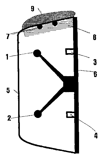
Further details and advantages of the invention and its embodiments are
explained below by means of the single drawing.
The drawing shows a cross-sectional view of a transmitter group of a
navigation antenna system for instrument landing, in particular a so-called
glide-path antenna. Such antennas are operated in a frequency range of
328 to 335 MHz. Each of the above mentioned transmitter groups
consists of a double row of dipoles 1 and 2, which are arranged in front
of a conductive back 6. Also fastened to back 6 is a monitor probe, of
which parts 3 and 4 are shown in the drawing. This particular case
represents a loop probe. The signal transmitted by dipoles 1 and 2 is also
picked up by the monitor probe and relayed to the evaluation unit (not
shown here) in a manner not shown here. The antenna feed arrangement
is not shown either, since it does not contribute to the understanding of
the invention; at any rate, these are functional elements of an antenna
which are known in prior art. A radome 5 is provided to protect the
transmitting antenna. In this particular case, it consists of a tub-like
housing of an almost rectangular cross section, as the drawing shows.
Here, the transmitting antenna is shown in the position in which it is
operated. Therefore, an accumulation 9 of snow can form on he top side
of the radome in winter. When the transmitting antenna is operated,
certain parts of the transmission signal are reflected due to the physical
-2-

~ CA 02390717 2002-05-08
properties of the snow cover. These reflected signal are received in the
same manner as the transmission signals coming from the dipoles and
impinging directly upon the monitor probe. This results in a signal
overlapped by the reflection signals which is relayed to the evaluation
unit. However, this signal does not correspond to the transmission signal
received by the aircraft.
According to the invention, a remedy is offered by attaching an additional
reflector 7 and an absorption layer 8 to the inside of radome 5, namely
where a snow accumulation 9 may normally be formed.
The reflector can be designed in a variety of ways. The drawing, for
example, shows reflector bars. Other solutions could include the use of a
conductive foil. To ensure that radiation reflected by rain or ice in the
front of radome 5, which in this case acts as a kind of corner reflector,
affects the monitor signal, reflector 7 is attached together with an
absorption layer 8 on the inside of radome 5. When such a combination is
applied, the transmitting antenna becomes largely insensitive to
atmospheric effects (rain, ice, snow).
-3-

Representative Drawing
A single figure which represents the drawing illustrating the invention.
Administrative Status

2024-08-01:As part of the Next Generation Patents (NGP) transition, the Canadian Patents Database (CPD) now contains a more detailed Event History, which replicates the Event Log of our new back-office solution.

Please note that "Inactive:" events refers to events no longer in use in our new back-office solution.

For a clearer understanding of the status of the application/patent presented on this page, the site Disclaimer , as well as the definitions for Patent , Event History , Maintenance Fee  and Payment History  should be consulted.

Event History

Description Date
Application Not Reinstated by Deadline 2004-11-01
Time Limit for Reversal Expired 2004-11-01
Deemed Abandoned - Failure to Respond to Maintenance Fee Notice 2003-10-30
Letter Sent 2002-10-29
Inactive: Notice - National entry - No RFE 2002-10-21
Inactive: Cover page published 2002-10-17
Inactive: Notice - National entry - No RFE 2002-10-15
Inactive: Applicant deleted 2002-10-15
Inactive: Single transfer 2002-08-21
Application Received - PCT 2002-08-01
National Entry Requirements Determined Compliant 2002-05-08
Application Published (Open to Public Inspection) 2001-05-17

Abandonment History

Abandonment Date Reason Reinstatement Date
2003-10-30

Maintenance Fee

The last payment was received on 2002-09-09

Note : If the full payment has not been received on or before the date indicated, a further fee may be required which may be one of the following

  • the reinstatement fee;
  • the late payment fee; or
  • additional fee to reverse deemed expiry.

Please refer to the CIPO Patent Fees web page to see all current fee amounts.

Fee History

Fee Type Anniversary Year Due Date Paid Date
Registration of a document 2002-05-08
Reinstatement (national entry) 2002-05-08
Basic national fee - standard 2002-05-08
MF (application, 2nd anniv.) - standard 02 2002-10-30 2002-09-09
Owners on Record

Note: Records showing the ownership history in alphabetical order.

Current Owners on Record
AIRSYS NAVIGATION SYSTEMS GMBH
Past Owners on Record
ERICH FRANKE
HERBERT KLEIBER
WOLF-DIETER BIERMANN
Past Owners that do not appear in the "Owners on Record" listing will appear in other documentation within the application.
Documents

To view selected files, please enter reCAPTCHA code :


To view images, click a link in the Document Description column. To download the documents, select one or more checkboxes in the first column and then click the "Download Selected in PDF format (Zip Archive)" or the "Download Selected as Single PDF" button.

List of published and non-published patent-specific documents on the CPD .

If you have any difficulty accessing content, you can call the Client Service Centre at 1-866-997-1936 or send them an e-mail at CIPO Client Service Centre.


Document
Description 
Date
(yyyy-mm-dd) 
Number of pages   Size of Image (KB) 
Representative drawing 2002-05-08 1 11
Abstract 2002-05-08 1 62
Description 2002-05-08 3 128
Claims 2002-05-08 1 28
Drawings 2002-05-08 1 13
Cover Page 2002-10-17 1 36
Notice of National Entry 2002-10-15 1 192
Notice of National Entry 2002-10-21 1 192
Courtesy - Certificate of registration (related document(s)) 2002-10-29 1 109
Courtesy - Abandonment Letter (Maintenance Fee) 2003-12-29 1 177
PCT 2002-05-08 11 384
PCT 2002-05-09 3 180
Fees 2002-09-09 1 36