Sélection de la langue

Search

Sommaire du brevet 2390717 

Énoncé de désistement de responsabilité concernant l'information provenant de tiers

Une partie des informations de ce site Web a été fournie par des sources externes. Le gouvernement du Canada n'assume aucune responsabilité concernant la précision, l'actualité ou la fiabilité des informations fournies par les sources externes. Les utilisateurs qui désirent employer cette information devraient consulter directement la source des informations. Le contenu fourni par les sources externes n'est pas assujetti aux exigences sur les langues officielles, la protection des renseignements personnels et l'accessibilité.

Disponibilité de l'Abrégé et des Revendications

L'apparition de différences dans le texte et l'image des Revendications et de l'Abrégé dépend du moment auquel le document est publié. Les textes des Revendications et de l'Abrégé sont affichés :

  • lorsque la demande peut être examinée par le public;
  • lorsque le brevet est émis (délivrance).
(12) Demande de brevet: (11) CA 2390717
(54) Titre français: ANTENNE EMETTRICE
(54) Titre anglais: TRANSMITTING ANTENNA
Statut: Réputée abandonnée et au-delà du délai pour le rétablissement - en attente de la réponse à l’avis de communication rejetée
Données bibliographiques
(51) Classification internationale des brevets (CIB):
  • H01Q 1/02 (2006.01)
  • H01Q 1/42 (2006.01)
(72) Inventeurs :
  • BIERMANN, WOLF-DIETER (Allemagne)
  • FRANKE, ERICH (Allemagne)
  • KLEIBER, HERBERT (Allemagne)
(73) Titulaires :
  • AIRSYS NAVIGATION SYSTEMS GMBH
(71) Demandeurs :
  • AIRSYS NAVIGATION SYSTEMS GMBH (Allemagne)
(74) Agent: GOWLING WLG (CANADA) LLP
(74) Co-agent:
(45) Délivré:
(86) Date de dépôt PCT: 2000-10-30
(87) Mise à la disponibilité du public: 2001-05-17
Licence disponible: S.O.
Cédé au domaine public: S.O.
(25) Langue des documents déposés: Anglais

Traité de coopération en matière de brevets (PCT): Oui
(86) Numéro de la demande PCT: PCT/EP2000/010651
(87) Numéro de publication internationale PCT: WO 2001035486
(85) Entrée nationale: 2002-05-08

(30) Données de priorité de la demande:
Numéro de la demande Pays / territoire Date
199 53 271.0 (Allemagne) 1999-11-06

Abrégés

Abrégé français

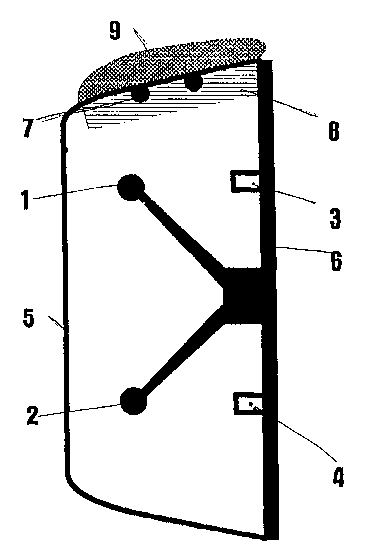
La présente invention concerne une antenne émettrice pour systèmes de navigation. Ces antennes sont en règle générale protégées par un radôme contre les influences mécaniques et chimiques des intempéries. Mais lorsque l'antenne est soumise à la pluie, à la glace ou à la neige, le signal d'antenne reçu par des sondes de surveillance est faussé. Pour éliminer le plus largement possible cette influence, la face interne du radôme est couverte, dans la région exposée aux intempéries, par une combinaison d'un réflecteur et d'une couche absorbante.


Abrégé anglais


The invention relates to a transmitting antenna for navigation systems.
Antennae of this type are normally protected against mechanical and chemical
atmospheric influences by a radome. Antenna signals received by the monitor
probe are, however, corrupted by weather-related accumulations on the radome
such as rain, ice or snow. In order to prevent this influence to the greatest
possible extent, a combination consisting of a reflector and of an absorption
layer is applied to the inside of the radome in the area on which rain, ice or
snow is expected to accumulate.

Revendications

Note : Les revendications sont présentées dans la langue officielle dans laquelle elles ont été soumises.


Claims
1. Transmitting antenna for navigational systems whereby the monitoring
probe(s) receive(s) the transmitted signal and relay(s) it to an internal
evaluation
unit in which the signal received by the monitoring probe(s) is compared with
the
signal relayed by the transmitting antenna from the antenna feed arrangement,
and whereby the transmitting antenna is surrounded by a protective housing, a
so-called radome,
characterized in that reflectors and an absorption layer are attached to the
inside
of the radome, in those areas of the radome which can be covered by snow, ice
or rain, depending on weather conditions.
2. Transmitting antenna according to Claim 1,characterized in that the
reflectors consist of metal bars.
3. Transmitting antenna according to Claim 1, characterized in that the
reflectors are attached in the form of a conductive layer on the inside
surface of
the radome.
4. Transmitting antenna according to Claim 1,characterized in that the
conductive layer consists of a metal foil.
-4-

Description

Note : Les descriptions sont présentées dans la langue officielle dans laquelle elles ont été soumises.


i
CA 02390717 2002-05-08
Transmitting antenna
The invention relates to a transmitting antenna for navigation systems.
When such antennas are employed in air traffic navigation systems, in
particular for an instrument landing, a high degree of accuracy is obviously
required. This includes the requirement that the signals must be
transmitted with the necessary accuracy and without disturbance.
In prior art, a conventional measure for monitoring the transmitted signals
is to use monitor probes. With such monitor probes, which are provided
either for the overall antenna or for the individual antenna transmitter
groups, as the case may warrant, the signal transmitted by the
transmitting antenna is received and relayed to an evaluation unit. A
conventional method is also used to relay to this evaluation unit a signal
derived from the antenna feed signal. A comparison between these two
signals allows conclusions about possible deviations, so that appropriate
corrections can be made.
In most cases, the above named antennas are set up and operated ~'1
outdoors. To protect them against atmospheric damage, the antennas are
accommodated in protective housings which are also called radomes.
In practice, it has often been found that weather-related accumulations on
the outside of the radome, such as snow and ice as well as rain, can
cause undesirable reflections. These reflections cause the monitor probes
to produce wrong or disturbed signals, resulting in a false evaluation.
Since radomes are always three-dimensional structures, the accumulations
mentioned above can never be completely eliminated by means of design
features.
It is therefore the abject of the present invention to create a transmitting
antenna for navigation systems in which the monitoring probes)
receives) the transmitted signal and relays) it to an internal evaluation
unit in which the signal received from the monitoring probes) is/are
compared with the signal received from the antenna feed device, and the
-1-

~i
CA 02390717 2002-05-08
transmitting antenna is surrounded by a protective housing, a so-called
radome, which allows the transmission of undisturbed signals, i.e. in
which sensitivity to weather-related accumulations is greatly reduced.
According to the invention, this object is achieved by means of reflectors
arranged on the inside of the radome and an absorption layer in those
areas of the radome which are subject to weather-related accumulations
of snow, ice, or rain.
This combination of two measures has proven to be effective and easy to
accomplish.
Further details and advantages of the invention and its embodiments are
explained below by means of the single drawing.
The drawing shows a cross-sectional view of a transmitter group of a
navigation antenna system for instrument landing, in particular a so-called
glide-path antenna. Such antennas are operated in a frequency range of
328 to 335 MHz. Each of the above mentioned transmitter groups
consists of a double row of dipoles 1 and 2, which are arranged in front
of a conductive back 6. Also fastened to back 6 is a monitor probe, of
which parts 3 and 4 are shown in the drawing. This particular case
represents a loop probe. The signal transmitted by dipoles 1 and 2 is also
picked up by the monitor probe and relayed to the evaluation unit (not
shown here) in a manner not shown here. The antenna feed arrangement
is not shown either, since it does not contribute to the understanding of
the invention; at any rate, these are functional elements of an antenna
which are known in prior art. A radome 5 is provided to protect the
transmitting antenna. In this particular case, it consists of a tub-like
housing of an almost rectangular cross section, as the drawing shows.
Here, the transmitting antenna is shown in the position in which it is
operated. Therefore, an accumulation 9 of snow can form on he top side
of the radome in winter. When the transmitting antenna is operated,
certain parts of the transmission signal are reflected due to the physical
-2-

~ CA 02390717 2002-05-08
properties of the snow cover. These reflected signal are received in the
same manner as the transmission signals coming from the dipoles and
impinging directly upon the monitor probe. This results in a signal
overlapped by the reflection signals which is relayed to the evaluation
unit. However, this signal does not correspond to the transmission signal
received by the aircraft.
According to the invention, a remedy is offered by attaching an additional
reflector 7 and an absorption layer 8 to the inside of radome 5, namely
where a snow accumulation 9 may normally be formed.
The reflector can be designed in a variety of ways. The drawing, for
example, shows reflector bars. Other solutions could include the use of a
conductive foil. To ensure that radiation reflected by rain or ice in the
front of radome 5, which in this case acts as a kind of corner reflector,
affects the monitor signal, reflector 7 is attached together with an
absorption layer 8 on the inside of radome 5. When such a combination is
applied, the transmitting antenna becomes largely insensitive to
atmospheric effects (rain, ice, snow).
-3-

Dessin représentatif
Une figure unique qui représente un dessin illustrant l'invention.
États administratifs

2024-08-01 : Dans le cadre de la transition vers les Brevets de nouvelle génération (BNG), la base de données sur les brevets canadiens (BDBC) contient désormais un Historique d'événement plus détaillé, qui reproduit le Journal des événements de notre nouvelle solution interne.

Veuillez noter que les événements débutant par « Inactive : » se réfèrent à des événements qui ne sont plus utilisés dans notre nouvelle solution interne.

Pour une meilleure compréhension de l'état de la demande ou brevet qui figure sur cette page, la rubrique Mise en garde , et les descriptions de Brevet , Historique d'événement , Taxes périodiques et Historique des paiements devraient être consultées.

Historique d'événement

Description Date
Demande non rétablie avant l'échéance 2004-11-01
Le délai pour l'annulation est expiré 2004-11-01
Réputée abandonnée - omission de répondre à un avis sur les taxes pour le maintien en état 2003-10-30
Lettre envoyée 2002-10-29
Inactive : Notice - Entrée phase nat. - Pas de RE 2002-10-21
Inactive : Page couverture publiée 2002-10-17
Inactive : Notice - Entrée phase nat. - Pas de RE 2002-10-15
Inactive : Demandeur supprimé 2002-10-15
Inactive : Transfert individuel 2002-08-21
Demande reçue - PCT 2002-08-01
Exigences pour l'entrée dans la phase nationale - jugée conforme 2002-05-08
Demande publiée (accessible au public) 2001-05-17

Historique d'abandonnement

Date d'abandonnement Raison Date de rétablissement
2003-10-30

Taxes périodiques

Le dernier paiement a été reçu le 2002-09-09

Avis : Si le paiement en totalité n'a pas été reçu au plus tard à la date indiquée, une taxe supplémentaire peut être imposée, soit une des taxes suivantes :

  • taxe de rétablissement ;
  • taxe pour paiement en souffrance ; ou
  • taxe additionnelle pour le renversement d'une péremption réputée.

Veuillez vous référer à la page web des taxes sur les brevets de l'OPIC pour voir tous les montants actuels des taxes.

Historique des taxes

Type de taxes Anniversaire Échéance Date payée
Enregistrement d'un document 2002-05-08
Rétablissement (phase nationale) 2002-05-08
Taxe nationale de base - générale 2002-05-08
TM (demande, 2e anniv.) - générale 02 2002-10-30 2002-09-09
Titulaires au dossier

Les titulaires actuels et antérieures au dossier sont affichés en ordre alphabétique.

Titulaires actuels au dossier
AIRSYS NAVIGATION SYSTEMS GMBH
Titulaires antérieures au dossier
ERICH FRANKE
HERBERT KLEIBER
WOLF-DIETER BIERMANN
Les propriétaires antérieurs qui ne figurent pas dans la liste des « Propriétaires au dossier » apparaîtront dans d'autres documents au dossier.
Documents

Pour visionner les fichiers sélectionnés, entrer le code reCAPTCHA :


Pour visualiser une image, cliquer sur un lien dans la colonne description du document. Pour télécharger l'image (les images), cliquer l'une ou plusieurs cases à cocher dans la première colonne et ensuite cliquer sur le bouton "Télécharger sélection en format PDF (archive Zip)" ou le bouton "Télécharger sélection (en un fichier PDF fusionné)".

Liste des documents de brevet publiés et non publiés sur la BDBC .

Si vous avez des difficultés à accéder au contenu, veuillez communiquer avec le Centre de services à la clientèle au 1-866-997-1936, ou envoyer un courriel au Centre de service à la clientèle de l'OPIC.


Description du
Document 
Date
(aaaa-mm-jj) 
Nombre de pages   Taille de l'image (Ko) 
Dessin représentatif 2002-05-08 1 11
Abrégé 2002-05-08 1 62
Description 2002-05-08 3 128
Revendications 2002-05-08 1 28
Dessins 2002-05-08 1 13
Page couverture 2002-10-17 1 36
Avis d'entree dans la phase nationale 2002-10-15 1 192
Avis d'entree dans la phase nationale 2002-10-21 1 192
Courtoisie - Certificat d'enregistrement (document(s) connexe(s)) 2002-10-29 1 109
Courtoisie - Lettre d'abandon (taxe de maintien en état) 2003-12-29 1 177
PCT 2002-05-08 11 384
PCT 2002-05-09 3 180
Taxes 2002-09-09 1 36