Note: Descriptions are shown in the official language in which they were submitted.
CA 02390774 2007-01-17
RESONANT ANTENNAS
BACKGROUND OF THE INVENTION
Field of the Invention
The invention relates to antennas and microwave transceivers.
Description of the Related Art
Conventional antennas often have linear dimensions that are of order of the
wavelength
of the radiation being received and/or transmitted. As an example a typical
radio transmitter
uses a dipole antenna whose length is about equal to 1/2 of the wavelength of
the waves being
transmitted. Such an antenna length provides for efficient coupling between
the antenna's
electrical driver and the radiation field.
Nevertheless, antennas whose linear dimensions are of order of the radiation
wavelength are not practical in many situations. In particular, cellular
telephones and handheld
wireless devices are small. Such devices provide limited space for antennas.
On the other hand,
small antennas couple inefficiently to the radiation at wavelengths often used
in cellular
telephones and handheld wireless devices.
SUMMARY OF THE INVENTION
Various embodiments use antennas that resonantly couple to external radiation
at
communication frequencies. Due to the resonant coupling, the antennas have
high sensitivities
to the radiation even if their linear dimensions are much smaller than '/2 the
radiation's
wavelength.
Certain exemplary embodiments can provide an apparatus, comprising: an object
formed of a metamaterial having an s whose real part is negative at microwave
frequencies; and
an amplifier module; CHARACTERIZED IN THAT: the apparatus includes electrodes
located
adjacent to opposite sides of the object; the amplifier module measures a
voltage between the
electrodes to measure an intensity of an electric field in the object; and the
object is an antenna
having a diameter that is 0.2 or less times a wavelength of the radiation that
the amplifier
module amplifies.
Certain exemplary embodiments can provide a method, comprising: exciting an
object
by receiving microwave radiation therein, the object having either a
dielectric constant with a
negative real part at microwave frequencies or a magnetic permeability with a
negative real part
CA 02390774 2007-01-17
la
at microwave frequencies; CHARACTERIZED IN THAT: the method further comprises:
measuring an electric or a magnetic field intensity internal or adjacent to
the object in response
to the object being excited by the microwave radiation, the object being a
metamaterial
antenna; and using the measured field intensity to determine data or voice
content of a
transmitted communication, the linear dimensions of the metamaterial antenna
being smaller
than the wavelength of the radiation.
Further embodiments of the present invention feature an apparatus that
includes an
object and one or more sensors located adjacent to or in the object. The
object is formed of a
material whose dielectric constant or magnetic permeability has a negative
real part at
microwave frequencies. The one or more sensors are located adjacent to or in
the object and
measure an intensity of an electric or a magnetic field therein.
CA 02390774 2007-01-17
2
Further embodiments of the present invention feature a method that
includes exciting an object by receiving microwave radiation and detecting a
field intensity internal or adjacent to the object in response to the object
being
excited by the microwave radiation. The object has either a dielectric
constant
with a negative real part at microwave frequencies or a magnetic permeability
with a negative real part at microwave frequencies.
BRIEF DESCRIPTION OF THE FIGURES
Figure 1 shows a receiver that includes a resonant dielectric antenna;
Figure 2 plots the response of an exemplary spherical dielectric antenna as
1o measured by two electrodes adjacent opposite poles of the antenna; and
Figure 3 shows a receiver that includes a resonant magnetically permeable
antenna; and
Figure 4 is a flow chart illustrating a method for receiving wireless
communications with receivers of Figure 1 or Figure 3.
DETAILED DESCRIPTION OF THE EMBODIMENTS
Various embodiments include antennas fabricated of manmade
metamaterials for which the dielectric constant (E) andlor magnetic
permeability ( ) is negative over a range of microwave frequencies. The
metamaterials are selected to cause the antennas to couple resonantly to
external radiation having communication frequencies. Due to the resonant
couplings, the antennas have a high sensitivity to the radiation even though
their linear dimensions are much smaller than the wavelength of the radiation.
The resonant coupling results from selecting the metamaterial to have
appropriate E and/or values. An appropriate selection of the metamaterial
depends on the shape of the object and the frequency range over which a
resonant response is desired. For spherical antennas s and/or must have real
parts approximately equal to "-2" in the frequency range, i.e., at
communication frequencies. For such values of E and/or ., a spherical
antenna is very sensitive to external radiation even if its diameter is much
smaller than'/2 of the radiation wavelength.
Figure 1 shows a microwave receiver 10 based on a dielectric antenna
14. The receiver 10 includes an amplifier module 12 and the dielectric
lilll ~I pl ~
CA 02390774 2002-06-14
Isaacs 2-9-1 3
antenna 14. The amplifier module 12 measures the voltage between electrodes
16, 18 that are located adjacent to opposite poles of the dielectric antenna
14.
The voltage measured by the electrodes 16, 18 is representative of the
intensity of the field inside the dielectric antenna 14, because the voltage
responds resonantly to external fields over the same frequency range for which
the antenna 14 responds resonantly. Exemplary electrodes 16, 18 are thin or
wire mesh devices that minimally perturb the electric field inside the
dielectric
antenna 14. The diameter of the antenna 14 is, preferably, 0.2 or less times
the
wavelength of radiation at a frequency that the amplifier module 10 is
configured to amplify.
For the small antenna 14, standard electrostatic theory defines how the
antenna responses to externally applied radiation. At distances, D, much
larger than the antenna's diameter, S, and much smaller than yi of the
radiation
wavelength, the external electric field, Ew, is approximately spatially
constant
and parallel. The field, F,w, is constant and parallel at distances, D,
because
the radiation wavelength is much larger than D, and the external electric
field,
E4.., only substantially varies for distances as large or larger than Wof the
radiation wavelength.
For the antenna 14, electrostatics theory detenmines how the value of
the electric field, Emdi,, inside antenna 14 depends on the value of the
spatially constant external electric field, 16,, i.e., the field at distances
large
compared to D and small compared to the wavelength. If the antenna 14 has a
dielectric constant, E, that is substantially constant near the relevant
radiation
frequency, electrostatics implies that:
E,i& = (3/[s + 2])E&,. .
From this electrostatics result, one sees that Eid& 4 - as E4 -2. Thus, even
a small external electric field F.h, produces a large voltage across
electrodes
16, 18 if the antenna's "E" is close to -2. Such a value of c produces a
resonant
response in the antienna 14 and makes the receiver very sensitive to external
radiation. Thus, producing a resonant antenna 14 requires constructing a
metamaterial whose s has an appropriate value in the desired communications
band.
3
. . 4, i ~I I~I r i~ 1 ~I CA 02390774 2002-06-14
Isaacs 2-9-1 4
Available materials do not have a dielectric constants equal to -2.
Rather composite materials can de fabricated to have an e whose real part is
close to -2 over a limited frequency range. The appropriate metamaterials
have negative E's for appropriate frequencies in a microwave range, e.g., from
about 1 giga-hertz (GHz) to about 100 GHz.
Manmade metamaterials that have appropriate properties in portions of
the above-mentioned frequency range are well-known in the art. Some such
metamaterials are described in "Experimental Verification of a Negative Index
of Refraction", by R. A. Shelby et al, Science, vol. 292 (2001) 77. Various
1o designs for such metamaterials are provided in "Composite Medium with
Simultaneously Negative Permeability and Permeability", D.R. Smith et al,
Physical Review Letters, vol. 84 (2000) 4184 and "Microwave transmission
through a two-dimensional, isotropic, left-handed metamaterial", by R.A.
Shelby et al, Applied Physics Letters, vol. 78 (2001) 489. Exemplary designs
produce metamaterials having F. and/or with negative values at frequencies
in the ranges of about 4.7 - 5.2 GHz and about 10.3 - 11.1 GHz.
Various designs for 2- and 3-dimensional manmade objects of
metamaterials include 2- and 3-dimensional arrays of conducting objects.
Various embodiments of the objects include single and multiple wire loops,
split-ring resonators, conducting strips, and combinations of these objects.
The exemplary objects made of one or multiple wire loops have resonant
frequencies that depend in known ways on the parameters defining the objects.
The dielectric constants and magnetic permeabilities of the metamaterials
depend on both the physical traits of the objects therein and the layout of
the
amays of objects. For wire loop objects, the resonant frequencies depend on
the wire thickness, the loop radii, the multiplicity of loops, and the spacing
of
the wires making up the loops. See e.g., ; "Loop-wire medium for
investigating plasmons at microwave frequencies", D.R. Smith et al, Applied
Physics Letters, vol. 75 (1999) 1425.
After selecting a frequency range and E and/or , the appropriate
parameter values for the objects and arrays that make up the metamaterial are
straightforward to determine by those of skill in the art. See. e.g., the
above-
4
N 1i [r 1I If I I Il
CA 02390774 2002-06-14
Isaacs 2-9-1 5
cited references. The useful metamaterials have a dielectric constant and/or
magnetic permeability whose real part is negative at the desinrd niicrowave
frequencies.
Since real materials cause losses, metamaterials typically have an c
and/or a with a nonzero imaginary part. For such resonant behavior, the
imaginary part of dielectric constant and/or magnetic permeability must be
small enough to not destroy the resonant response of the antenna and large
enough to provide adequate breadth to the resonant response. Typically, one
desires a resonant response over a band of frequencies. Methods for
lo introducing losses into the metamaterials are also known to those of sldll
in
the art. See e.g., the above-mentioned References.
At frequencies that produce resonant responses in antenna 14, the
nonzero imaginary part of E reduces the infinite response to an external
electric field to a finite peak with a frequency spread as seen in Figure 2.
Preferred receivers 10 employ metamaterials whose s has a larger enough
imaginary part to insure that the desired communication band provokes a
resonant response in the antenna 14. Known metamaterials produce values of
Im[c(co)]/Re[E((u)] = Auu/tw _ 0.03 - 0.05 and 5 0.1.
Figure 3 shows a receiver 20 based on a magnetically permeable
spherical antenna 22. The receiver 20 also includes a pickup coi124, and an
amplifier module 26. The antenna 22 is constructed of a magnetic
metamaterial with an appropriate . In the antenna 22, the magnetic
permeability, , rather than dielectric constant s causes a resonant response
to
external radiation. For the antenna 22, magnetostatics rather than
electrostatics enable relating a magnetic field inside the antenna, B;ddef to
an
external magnetic field, Bw. Provided that the external magnetic field, Bw,
has a wavelength large compared to the diameter of the antenna 22,
magnetostatics implies that:
Bi.ide = (3 /[ + 2l)Braz =
If has a value close to "-2" in a desired fmquency range, the spherical
antenna 22 produces a resonant response to externally applied radiation. In
5
~i . I I il i 6 ~
CA 02390774 2002-06-14
Isaacs 2-9-1 6
such a case, the antenna 22 greatly increases the sensitivity of receiver 20
to
applied external radiation.
Again, the magnetically permeable metamaterial has a whose
imaginary part is nonzero due to internal losses. The imaginary part of is
designed to be large enough to insure that the antenna 22 responds resonantly
over a desired frequency band. Methods for introducing losses into
metamaterials are known to those of skill in the art.
While the above-described receivers 10, 20 use spherical antennas 14,
22, other embodiments use antennas with different shapes. Exemplary
antenna shapes include ellipsoids, cylinders, and cubes. For these other
shapes, the associated antennas resonantly respond to external radiation for
values of the real part of an F and/or that differ from "-2". The parameters
for the metamaterial depend on the geometry of the antenna and are selected to
provide an appropriate negative value of F. and/or in an appropriate
microwave band.
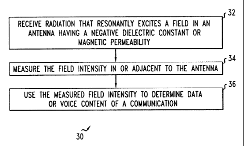
Figure 4 illustrates a method 30 for receiving wireless data or voice
communications with receiver 10 of Figures 1 or receiver 20 of Figure 3. The
method 30 includes receiving microwave radiation that resonantly excites an
electric or magnetic field intensity in an antenna (step 32). The antenna has
either a dielectric constant with a negative real part at microwave
frequencies
or a magnetic permeability with a negative real part at microwave frequencies.
Exemplary antennas include objects made of metamaterials. In response being
excited, the intensity of the electric or magnetic field in or adjacent to the
antenna is measured (step 34). The field intensity is measured by one or more
sensors that are located internal to or adjacent to the antenna The method 30
includes using the measured field intensity to determine data or voice content
of a communication transmitted in a preselected frequency range (step 36).
The invention is intended to include other embodiments that will be
obvious to one of skill in the art in light of the disclosure, figures and
claims.
6