Note: Descriptions are shown in the official language in which they were submitted.
'- "", ~~'~'~ ° 1~?~~ tr~.HNK ROME COMISkY .RND MCCAULEY -
~'g7*~155kt0114989239g4465 I ~JS003023
08-11-2001
,, , ~: ! ~
CA 023~90910 2002-05-17 ~~1:
. ' .:~I .
,~J.
' A;
. a,.
!ri
'. ,f~3
. _ ~:
' . . ~~
' ,,,I;
APPARATUS AND METHOD FOR COI HE 'ABM YOLUME COM_ PU'K'ED .
. .~ TO1VI4GRAPI~Y ~MAMIMOGR,A.P~iY
»;efereace to Related Annl'c lion ' ' ' . ~ ''~~ ' .
This application claims the benefit of U.S. Provisional Application No.
60116b,223, .
. . . ~,.
v .;..;
filed November 18, 1999. . ~ .~~'
. ' . ~.
~~f
~;:
Bac d of the Invention ' . ~ v~ . ~ .
:..: . . .., i
,. . .
~.;;
Breast cancer represents a sigrdficant health pxoblem. ll~ore than 188,000 new
cases
are diagnosed, and.nearly 45,000 women, die of the disease each year~in the
United States.
- ! ~ ; ,; ~ .
~ ~ 'The clinical goal of breast imaging is to detect tumor masses ~wheri~
they are as small '
.;,
i;
as possible, preferably less than 10 nnm in diameter. It is reported that
women with .
. . . . - ;' i,;
mammogt"dphicahy. detected, 1-10 muY invasive breast c~aicnnoma have a 939'0
16=year
~ . . ,r~ .
.~.. ~_ . ~;. . ~'
swrvival rate. - . . . ~;,
. , If: ' . ' ,
Conventional screen film mamnsog~aphy is the tiiost effective toot foi the
early
,;
i,::
is detection of breast cancer currentlyavailable.' However; n~amnaography has
relatively low
sensitivity to detect small breast cancers (under several 6,tnillimeters).
Specificity and the
...
. . , , , .. . y .;.,
positive predictive value of mam>aiograpliy remain limited owing to an overaap
in the
. . f ' .I>t , . -
. . . . , :, . r~;.: . . . .
appearances of benign and, malignant lesions. Limited sensitivity and
specificity in bireast
:f;; ~ .
cancer detection of mammography are; dut~.to its poor, contxast delectability,
which is
. :.
. ,... - ..
zo common for ;all types,of projection imaging teclaniques,~'(projection
imaging can only have
,f,
;;, .
up to 10% contrast, delectability). The sensitivity with fivhich conventional
mammography
;,
can identify malignant tumors iz~ the pre-clinical phase ;will largely be
affected by the nature '
of the surrauz~ding brealst parenchyma', Detection of calcifications will be
influezieed to a .
lesser ' 3
,:
.' '
oonr.~~ nn~ ss~s~"~«.,
EmofangszqMENDED SHEET
CA 02390910 2002-05-17
WO 01/35829 PCT/US00/30239
2
degree by the surrounding tissue. The perception of breast masses without
associated
calcification, representing the majority of tumors in patients with detected
carcinomas, is
greatly influenced by the mammographic parenchymal pattern. Thus conventional
mammography is often not able to directly detect tumors of a few millimeters
due to poor low
contrast resolution. Conventional mammography requires ultrahigh resolution
(50 - 100
~m/pixel) to image microcalcifications to compensate for its poor contrast
resolution.
Mammography fails to initially demonstrate 30%-35% of cancers. In addition,
not all breast
cancers detected with mammography will be found early enough to cure. At best,
it appears
that conventional mammography can reduce the death rate by up to 50%. This is
an
to important gain, but there is considerable room for improvement in early
detection of breast
cancer.
Relatively low specificity of mammography results in biopsy for indeterminate
cases
despite the disadvantages of higher cost and the stress it imposes on
patients. There is a need
for more accurate characterization of breast lesions in order to reduce the
biopsy rate and
false-positive rate of biopsy.
There are several radiological or biological characteristics of breast
carcinoma that
can be imaged. First, carcinoma has different x-ray linear attenuation
coefficients from
surrounding tissues, as shown in figure 1. Second, carcinoma has a
substantially higher
volume growth rate compared to a benign tumor which lacks growth. Third,
carcinoma has
2o patterns distinguishable from those of a benign tumor. Fourth, benign
tumors show no
contrast enhancement after intravenous contrast injection. Fifth, the presence
of
neovascularity can indicate cancer. Conventional mammography relies mainly on
the first
characteristic and partially uses the third characteristic for breast cancer
detection. Since
SUBSTITUTE SHEET (RULE 26)
CA 02390910 2002-05-17
WO 01/35829 PCT/US00/30239
mammography is a two-dimensional static imaging technique, it cannot provide
any
information regarding characteristics 2, 4, or 5.
Currently, radiological evaluation of breast cancer is important not only for
early
detection of disease, but also for staging and monitoring response to
treatment. So far,
conventional screen film mammography has been shown to be the most cost-
effective tool for
the early detection of breast cancer. The specificity and positive predictive
value of
mammography, however, remain limited, owing to an overlap in the appearances
of benign
and malignant lesions and to poor contrast detectability, which is common for
all projection
imaging techniques. Projection imaging can have only up to 10% contrast
detectability.
1o Biopsy is therefore often necessary in indeterminate cases, despite the
disadvantages of
higher cost and the stress it imposes on patients. There is therefore a need
for more accurate
characterization of breast lesions in order to reduce the biopsy rate.
In the last decade, MRI of the breast has gained a role in clarifying
indeterminate
cases after mammography and/or ultrasound, especially after breast surgery and
in detecting
multifocal breast cancers. However, the integration of MR into routine
clinical practice has
been hampered by a number of limitations, including long scanning times and
the high cost of
MR examinations. Additionally, many patients cannot undergo MR because of MR
contraindications (e.g., aneurysm clips, pacemaker) or serious claustrophobia.
Characterization of breast lesions on MR has been based largely on the
differential
2o rates of enhancement between benign and malignant lesions. The constant
trade-off between
spatial and temporal resolution in MR has made it difficult to achieve the
spatial resolution
necessary for improved lesion characterization.
SUBSTITUTE SHEET (RULE 26)
~~~'e~l ~ 1s~~~ BLRNK ROME COM1SK1'eRND MCGAULEY -~y$7*00255it022498923994465
h US00302?
- 08-11-2001 ---..~--. ,' ~~~ .
CA 02390910 2002-05-1~7 . '
' ~i.
ti
:I' '
i ... . i( .
. ~ , 4 ;' .
~i;
.,
. . , ,
. Standard fan lieaat computed tomography (CT); including spiral CT, has been
' .
evaluated as a potential tool for the characterizatian of breast lessons.Most
previous work
has been based on the traditional or helical~technique usin~~the whole body
scanner. That
' , .;,~ ~ ~; . .
technique,, however, suffers from a number.of disadvar~ta~es including
significantly increased .
~i,
' S radiation exposure due to the fact that standard CT can not be used
to.target only the breast, '
. , , . . . . ~(; ,
.'
so that the.xnajority of x-rays ate wasted on whole body scanning.' That
leads'to relatively ' .
., ~, ~. ,
.low in-plane spatial resolution (typically ~ 1.0 Ip/mm), even lower through
plane resolution
.: ~,
(less than or equal to 0.5 lp/mm in the direction perpendicular to slices),
and prolonged
volume scanning times, since spiral CT scans the whole volwme slice by slice
and takes 120 .
. 10 ~ seconds far the whole breast scan. . It still takes 15.- 30 s seconds
for the latest mufti-ring~spiral '
. ...
CT for l mm/six~ and ~ 12 cm coveiage. ~ . ~ ~ ~ ~ y' ~ . . ~ .
. ; ~:.~ ~ ,, ,
Ultrasound has poor resolution in characterizing Lesion margins and.
identi~ing .
'!1: .
microcalcifications. CTltcasvund is also extremely operat~i dependent:
~:(~ . : ~ ..
;;
rn addition, for conventional mammography, compression is essential for better
low-
,.. . . ,;: , ~ .
1s. contrast delectability.' However, patients aide uncomfortable even
though.compression may
not be harmful to, them. . , : ~ = :. . . ,~ : , ., . . ; , w. , . .:
;~; .
. A method and system for cone-beam to~mographyreconstruction are
taught~in~VVO
;, ; :. '- =f' ' '
i.
99101066. However, the above-noted issues relating to inararnography are not
addressed.
. . . , ~ '3 ' . , . . ..
. . ,, .
' . . ' ' ' . 7 . . ,
[F! ,
,_,.
' . ,; . '',;1~ ' . '
.. . . ' ' . p.~ '
. . . . . . . . . .. .. . , p .. . . ..
. . . . . . . . ..i!t . , .
~.nte~MltC!'lSO9lect.,n ' . . ' ..
Empfanss qMENDED SHEET
CA 02390910 2002-05-17
WO 01/35829 PCT/US00/30239
Summary of the Invention
It will be readily apparent from the foregoing that a need exists in the art
for a
mammography imaging system and method which overcome the above-noted
limitations of
conventional techniques.
It is therefore a primary object of the invention to provide a clinically
useful three-
dimensional mammography technique for accurate detection of breast cancer.
It is another object of the invention to provide a mammography technique which
can
operate with only a single fast volume scanning to provide true three-
dimensional (3D)
description of breast anatomy with high isotropic spatial resolution and
lesion location, while
l0 conventional mammography only provides two-dimensional projection images.
It is yet another object of the invention to provide imaging technique to
tomographically isolate a breast tumor from the other objects in adjacent
planes,
consequently eliminate overlap and remove superimposed structures.
15 It is yet another object of the invention to provide higher contrast
resolution compared
with conventional mammography and adequate spatial resolution for breast
cancer detection.
It is yet another object of the invention to improve the detectability of
breast
carcinoma (tumors) of a few millimeters in size due to much better low
contrast resolution,
compared to conventional mammography.
20 It is yet another object of the invention to provide high resolution volume
of interest
(VOI) reconstruction mode for target imaging and better characterization of
breast tumors
three-dimensionally compared with conventional mammography.
SUBSTITUTE SHEET (RULE 26)
CA 02390910 2002-05-17
WO 01/35829 PCT/US00/30239
It is yet another object of the invention to provide a three-dimensional
tomographic
reconstruction technique to detect the difference of x-ray linear attenuation
coefficients of
carcinoma from surrounding tissue. (carcinoma has different x-ray linear
attenuation
coefficients from surrounding tissue.)
It is yet another object of the invention to provide accurate depiction of
breast tumor
border pattern for better characterization of breast tumors compared with
conventional
mammography (carcinoma has distinguishable border patterns from those of a
benign tumor).
It is yet another object of the invention to improve specificity in breast
cancer
detection compared with conventional mammography by allowing more precise
measurement
of change in lesion volume over relatively short periods of time (carcinoma
has a much faster
volume growth rate than a benign tumor).
It is yet another object of the invention to provide a mammography technique
usable
with intravenous (IV) injection of iodine contrast to improve detection and
characterization of
breast tumors by allowing an assessment of lesion vascularity and enhancement
rate (a
1s benign tumor and a malignant tumor have different contrast enhancement
rates).
It is yet another object of the invention to provide a mammography technique
usable with
intravenous (IV) injection of iodine contrast to assess breast tumor
angiogenesis non-
invasively.
It is yet another object of the invention to increase patient comfort by
decreasing the
2o amount of breast compression required.
It is yet another object of the invention to use CBVCTM image-based volume
growth
measurement technique (both positive gro~~th and negative growth) to determine
malignancy
SUBSTITUTE SHEET (RULE 26)
CA 02390910 2002-05-17
WO 01/35829 PCT/US00/30239
of breast tumors and to monitor the effect of breast cancer treatment (this
method can be also
used for other malignancies, such as lung cancer).
It is yet another object of the invention to use higher x-ray energies than
those used in
conventional mammography, for breast imaging to increase penetration, improve
image
quality and reduce patient radiation dose.
It is yet another object of the invention to perform mufti-resolution volume
tomographic reconstruction from the same set ofprojection images to improve
the
dectectibility of microcacification and breast carcinoma (tumors), better
characterize breast
tumors, and consequently reduce the total accumulative dose for patient.
to It is yet another object of the invention to use a CBVCTM image-based
computer
aided diagnostic technique to improve the detectibility and characterization
of breast
carcinoma (tumors).
It is yet another object of the invention to improve sensitivity of breast
cancer
detection and thereby further reduce mortality of breast cancer by detecting
small breast
cancers that can not be detected by conventional mammography.
It is yet another object of the invention to improve specificity of
mammography and
greatly reduce the biopsy rate.
It is yet another object of the invention to provide adequate image quality
for the
mammographically dense breast.
It is yet another object of the invention to facilitate 3D image-guided biopsy
procedures.
It is yet another object of the invention to allow accurate assessment of
cancer extent
for both better pre-surgical planning, especially in limited resections, and
radiation therapy
SUBSTITUTE SHEET (RULE 26)
CA 02390910 2002-05-17
WO 01/35829 PCT/US00/30239
treatment planning, as well as for more accurate monitoring of breast cancer
response to
treatments.
To achieve the above and other objects, the present invention is directed to a
system
and method incorporating a cone beam volume tomographic reconstruction
technique with
the recently developed flat panel detector to achieve cone beam volume
computed
tomographic mammography (CBVCTM). With a cone beam geometry and a flat panel
detector, a flat panel-based cone beam volume computed tomography mammography
(CBVCTM) imaging system can be constructed, and three-dimensional (3D)
reconstructions
of a breast from a single fast volume scan
1o can be obtained. In contrast to conventional mammography, the flat panel-
based CBVCTM
system can provide the ability to tomographically isolate an object of
interest (e.g., a lesion)
from an object (e.g., other lesion or calcification) in adjacent planes. The
3D tomographic
reconstructions eliminate lesion overlap and provide a complete, true 3D
description of the
breast anatomy. In contrast to existing computed tomography (CT) with an
intraslice
resolution of 1.0 lp/mm and through plane resolution of 0.5 lp/mm, the CBVCTM
reconstructions can have 2.0 lp/mm or better of isotropic spatial resolution
(or, more
generally, better than 1 lp/mm) along all three axes. The invention is further
directed to an
ultrahigh resolution volume of interest (VOI) reconstruction using the zoom
mode of the flat
panel detector to achieve up to 5.0 lp/mm resolution. Thus, CBVCTM can have
many times
2o better contrast detectability (tomographic imaging can have up to 0.1 %
contrast detectability)
than that of conventional mammography.
SUBSTITUTE SHEET (RULE 26)
CA 02390910 2002-05-17
WO 01/35829 PCT/US00/30239
Various scanning geometries can be used. It is contemplated that either a
circle scan
or a circle-plus-line (CPL) scan will be used, depending on the size of the
breast. However,
other geometries, such as spiral, can be used instead.
The present invention provides better detection of breast cancers, better
lesion
characterization, and more accurate preoperative and postoperative information
on breast
anatomy, thus reducing the negative biopsy rate.
The present imaging technique has significant clinical impact on breast cancer
detection, diagnosis and the evaluation of the effectiveness of therapy.
Because of its
excellent low contrast detectability and high and isotropic resolution, the
present invention
1o significantly improves the accuracy of breast lesion detection, and hence
greatly reduces the
biopsy rate. The potential clinical applications of such a modality are in the
imaging of the
mammographically indeterminate lesions, the mammographically dense breast and
the post-
surgical breast. Currently, most mammographically indeterminate lesions end up
being
biopsied in order to arnve at a definitive diagnosis. It is well known that
the usefulness of
mammography in patients with dense breasts is limited and that additional
imaging or biopsy
is frequently required. The use of an imaging modality that has a capability
for multiplanar
and volumetric data acquisition has the potential to improve lesion
characterization in dense
breast tissue. The higher spatial resolution afforded CBVCTM can potentially
improve the
differentiation of recurrence and form of post-surgical changes.
2o The present invention provides very high-resolution tomographic images by
zooming
in on small lesions or specific regions within a tumor. Detailed interrogation
of specific areas
within a lesion, e.g., microcalcifications, necrotic and cystic as well as
areas of intraductal
extension enables more accurate characterization of breast lesions. The use of
contrast
SUBSTITUTE SHEET (RULE 26)
CA 02390910 2002-05-17
WO 01/35829 PCT/US00/30239
material and dynamic imaging provides additional temporal information, which,
together
with morphological features, enhances specificity and reduces the biopsy rate.
Tumor angiogenesis is an independent prognostic indicator in breast cancer.
Currently, angiogenesis is determined by assessing microvessel density in
pathologic
5 specimens. However, researchers have also detected good correlation between
contrast
enhancement and microvessel density. The use of contrast medium in an imaging
modality
that provides very high spatial and temporal resolution offers a non-invasive
method to assess
tumor angiogenesis. Additionally, the acquisition of volumetric data with 3D
rendering
allows multiplanar imaging and better presurgical planning, especially in
limited resections.
l0 In summary, the introduction of CBVCTM, with the potential for obtaining a
very
high spatial resolution tomographic images, offers improved lesion
characterization in
mammographically indeterminate breast lesions with a view to reducing the
biopsy rate. It
also offers the advantages of enhancing preoperative and postoperative
planning.
CBVCTM has the capacity to provide information regarding characteristics 1-S
discussed above with reference to the prior art to improve lesion detection
and
characterization.
In a preferred embodiment, the patient lies face down on an ergonomic patient
table
having one or two breast holes. The gantry holding the x-ray source and the
flat panel
detector rotates below the table to image the breast or two breasts. One
advantage of having
two breast holes is to preserve the geometric relationship between the
breasts. In an
alternative embodiment, the patient stands before the gantry with straps to
hold a patient still.
SUBSTITUTE SHEET (RULE 26)
CA 02390910 2002-05-17
WO 01/35829 PCT/US00/30239
11
A further modification of the present invention uses an ultra-high-resolution
volume-
of interest (VOI) reconstruction mode to focus on a suspicious lesion. The
ultra-high-
resolution VOI reconstruction mode is analogous to magnified mammography.
CBVCTM will provide very high-resolution tomographic images by zooming in on
small lesions or specific regions within a tumor. Detailed interrogation of
specific areas
within a lesion (i.e. microcalcifications, necrosis and cysts as well as areas
of intraductal
extension without overlap structures) will enable more accurate
characterization of breast
lesions.
CBVCTM will potentially provide a non-invasive method to assess tumor
to angiogenesis. Recent work has established that tumor angiogenesis is an
independent
prognostic indicator in breast cancer. Currently, angiogenesis is determined
by assessing
microvessel density in pathologic specimens. However, researchers have also
detected good
correlation between contrast enhancement and microvessel density. The use of
contrast media
in an imaging modality that provides very high spatial and temporal resolution
may offer a
non-invasive method to assess tumor angiogenesis.
With the present invention, a CBVCTM scan can be completed rapidly, and
several
sets of scans can be performed continuously for dynamic contrast studies and
angiogenesis
studies.
SUBSTITUTE SHEET (RULE 26)
CA 02390910 2002-05-17
WO 01/35829 PCT/US00/30239
12
Brief Description of the Drawings
A preferred embodiment of the present invention will be set forth in detail
with
reference to the drawings, in which:
Fig. 1 shows the linear attenuation coefficients of various tissues which may
be found
in a healthy or diseased breast;
Figs. 2A-2C show a schematic diagram of a cone beam volume CT mammography
scanner according to the preferred embodiment;
Fig. 2D shows one variation of the scanner of Figs. 2A-2C;
Fig. 2E shows another variation of the scanner of Figs. 2A-2C;
to Fig. 2F shows yet another variation of the scanner of Figs 2A-2C (the
version to move
the patient table up and down instead of the gantry);
Fig. 3 shows a block diagram of the circuitry used in the scanner of Figs. 2A-
2F;
Fig. 4 shows a scanning geometry which can be implemented in the scanner of
Figs.
2A-2F;
Figs. 5A and SB show a setup for taking scout images for scatter correction;
Figs. 6A-6C show schematic diagrams of a dynamic collimator for use with the
scanner of Figs. 2A-2F; and
Figs. 7A-7G show steps in the operation of the device of Figs. 2A-2F.
SUBSTITUTE SHEET (RULE 26)
CA 02390910 2002-05-17
WO 01/35829 PCT/US00/30239
13
Detailed Description of the Preferred Embodiment
A preferred embodiment and an alternative embodiment of the present invention
will
now be set forth in detail with reference to the drawings, in which the same
reference
numerals refer to the same components throughout.
The limitations accompanying conventional mammography are addressed by
incorporating a cone beam volume CT reconstruction technique with a flat panel
detector.
With cone beam geometry and a flat panel detector, a flat panel-based cone
beam volume
computed tomography mammography (CBVCTM) imaging system can be constructed as
shown in Figs. 2A-2F, and three-dimensional (3D) reconstructions of a breast
from a single
l0 fast volume scan can be obtained. In contrast to conventional mammography,
the flat panel-
based CBVCTM system provides the ability to tomographically isolate an object
of interest
(e.g. a lesion) from the other objects in adjacent planes (e.g. other lesion
or calcification). The
3D tomographic reconstructions eliminate lesion overlap and provide a
complete, true 3D
description of breast anatomy. In contrast to conventional computed tomography
(CT) with
15 an intraslice resolution of -~-1.0 lp/mm and through plane resolution of
0.5 lp/mm, the
CBVCTM reconstructions can have 2.0 Ip/mm or better of isotropic spatial
resolution. An
ultrahigh resolution volume of interest (VOI) reconstruction can be produced
by using the
zoom mode of the flat panel detector to achieve up to S.0 lp/mm or better
resolution,
depending on the size of x-ray focal spot and inherent detector resolution.
20 An FPD-based CBVCTM can be built with slip ring technology. A slip ring is
an
electromechanical device allowing the transmission of electrical power,
signals or both across
a rotating interface. One source of slip rings is Fabricast, Inc., of South El
Monte, California,
U.S.A.
SUBSTITUTE SHEET (RULE 26)
CA 02390910 2002-05-17
WO 01/35829 PCT/US00/30239
14
The schematic design of the CBVCTM scanner is shown in Figs. 2A-2F. The
CBVCTM scanner has an ergonomic patent table design and scanning geometry
especially
suitable for target imaging.
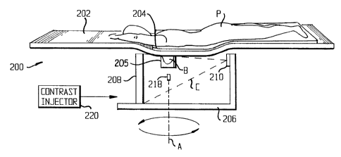
In the scanner 200, the patient P rests on an ergonomically formed table 202
so that
the breast B to be scanned descends through a hole 204 in the table 202 into a
breast holder
205. The breast holder 205, which will be described in greater detail below,
forms the breast
B into a cylindrical shape for scanning, which is more comfortable for most
patients than the
conventional flattened shape.
Below the table 202, a gantry 206 supports a detector 208 and an x-ray tube
210, one
to on either side of the breast holder 205. The gantry is turned by a motor
212 to be rotatable
around an axis A passing through the breast holder 205, so that as the x-ray
tube travels along
an orbit O, the breast B remains in the path of a cone beam C emitted by the x-
ray tube 210.
The gantry is also movable by a motor 214 to go up and down along a vertical
path V.
Alternatively, the table 202 can be moved up and down along a vertical path V.
The detector
208 can be moved toward and away from the axis A by a motor 216 to change the
magnification factor if necessary.
To assure the geometric reproducibility of breast imaging and proper imaging
of the
chest wall, the breast holder 205 is relatively rigid and is made of a
material with low x-ray
attenuation. The breast holder is shown as being part of the table 202, but it
can alternatively
2o be made part of the gantry 206. The breast holder 205 pulls the breast out
of the chest wall to
assure proper imaging of the chest wall and applies a light and reproducible
compression to
form the breast into a cylindrical shape. There may be a cushion inside the
breast holder to
assure the patient's comfort. Then a piston 218 may be used to push the nipple
toward the
SUBSTITUTE SHEET (RULE 26)
CA 02390910 2002-05-17
WO 01/35829 PCT/US00/30239
chest wall to reduce z-direction coverage by a couple of centimeters. That
piston-pushing
reduces the required cone angle of the x-ray beam. Consequently, with the
piston-pushing,
the majority of breast scans (for breasts < 10 cm in height) may be achieved
by using only the
circular scan mode, and for a large breast, the number of required line
projections may be
5 reduced. In addition, the piston-pushing improves uniformity of breast
thickness.
A contrast injector 220 can be provided for contrast enhanced tomographic
imaging,
angiogenesis studies and some other dynamic contrast studies. Various contrast
injection
media, such as iodine, are known in the art. It is not always necessary to
inject a contrast
medium into the patient.
to The table 202 can be replaced with the table 202' of Fig. 2D. The table
202' is
formed like the table 202, except that two breast holes 204 are provided, each
with a breast
holder 205. The table 202' is movable. One breast is moved into the imaging
field and is
scanned first. Then the other breast is moved into the imaging field and
scanned. Thus, the
geometric relationship between the breasts is preserved. Alternatively, two
breasts with two
is breast holders can be scanned together.
Alternatively, the scan or scans can be performed while the patient is
standing. As
shown in Fig. 2E, in such a scanning system 200', a breast holder 205 is
supported by a stand
222 to support a breast of a standing patient. Alternatively, two breast
holders 205 can be
provided on the stand 222. One breast is moved into the imaging field and is
scanned first.
2o Then the other breast is moved into the imaging field and scanned.
Alternatively, two breasts
with two breast holders can be scanned together. The gantry 206, holding the
detector 208
and the x-ray tube 210, is oriented to rotate around a horizontal axis A'
rather than the
SUBSTITUTE SHEET (RULE 26)
CA 02390910 2002-05-17
WO 01/35829 PCT/US00/30239
16
vertical axis A of Figs. 2A-2C. In other respects, the system 200' can be like
the system
shown in Figs. 2A-2C.
The circuitry of the scanner 200 is shown in Fig. 3. A computer 302 on the
gantry 206
is connected through a slip ring 304 on a shaft of the gantry 206 to a host
computer system
306. The computer 302 on the gantry 206 is also in communication with the
detector 208,
while both computers 302 and 306 are in communication with various other
devices on the
gantry 206, as explained below. The computer 306 is further in communication
with a user
control and graphics user interface 308.
to In the computer 302 on the gantry 206, the CPU 310 is in communication with
the
detector 208 through a digital frame grabber 312 and a flat panel controller
314. The CPU
310 is also in communication with a memory buffer 316, disk storage 318 and a
real-time
lossless image compression module 320; through the compression module 320, the
CPU 310
communicates with a CBVCTM data transfer module 322 on the gantry 206. The CPU
310
directly communicates with two other devices on the gantry, namely, the gantry
control 324
and the x-ray control 326. The x-ray control 326 can control the exposure
pulse length,
exposure timing, and exposure pulse numbers. In addition, the x-ray control
326 can real-
timely (dynamically) change x-ray exposure level from projection to projection
to achieve
optimal x-ray dose efficiency without degrading reconstructed image quality.
2o In the host computer system 306, a host computer CPU 328 communicates with
the
data transfer module 322, both directly and through a real-time image
decompression module
330. The CPU 328 is also in communication with a memory buffer 332, disk
storage 334 and
a parallel accelerating image reconstruction and processing module 336.
Through an image
SUBSTITUTE SHEET (RULE 26)
CA 02390910 2002-05-17
WO 01/35829 PCTlCTS00/30239
17
output 338, the CPU 328 communicates with the interface 308. The CPU's 310 and
328
communicate with each other through the slip ring 304. Also, although it is
not shown in Fig.
3 for simplicity, all communication between components on the gantry 206 and
the host
computer system 306 take place through the slip ring 304.
The CPU 328 with the Parallel Accelerating Image Reconstruction and Processing
Module 336 can perform mufti-resolution volume tomographic reconstruction from
the same
set of projection images to improve the detectability of microcalcification
and breast
carcinoma (tumors), better characterize breast tumors and consequently reduce
the total
accumulative dose for the patient. The CPU 328 can also be used in a CBVCTM
image-
to based computer aided diagnosis technique to improve the detectability and
characterization of
breast carcinoma.
The slip ring 304 and a fast gantry 206 permit optimal CPL scanning with a
quasi-
spiral scanning scheme and fast dynamic contrast studies. With that design, a
CBVCTM scan
can be completed within a few seconds, and several sets of scans can be
performed
15 continuously for dynamic contrast studies and angiogenesis studies.
If the locus of an x-ray source and a detector is a single circle during cone
beam
scanning (single circle cone-beam geometry), an incomplete set of projection
data is
acquired. The incompleteness of the projection data results in some
unavoidable blurring in
the planes away from the central z-plane and resolution loss in the z
direction. Using
2o Feldkamp's algorithm which is based on a single circle cone beam geometry,
the magnitude
of the reconstruction error due to the incompleteness of projection data is
increased with cone
angle. Computer simulation indicates that for mammography imaging and an
average breast
size (10 cm in height or smaller), the reconstruction error is relatively
small (<5%), and no
SUBSTITUTE SHEET (RULE 26)
CA 02390910 2002-05-17
WO 01/35829 PCT/CTS00/30239
18
streak artifacts can be observed. A modified Feldkamp's algorithm is used for
small and
average breast sizes (< 10 cm in height), and a circle-plus-lines (CPL) cone
beam orbit and its
corresponding filter backprojection algorithm are used for a large breast (>
10 cm in height).
That approach practically solves the problem of the incompleteness of
projection data from a
single circle cone beam geometry for mammography scanning. A suitable modified
Feldkamp's algorithm is taught in Hu, H., "A new cone beam reconstruction
algorithm and
its application to circular orbits," SPIE 1994; 2163:223-234. A suitable
algorithm for circle-
plus-a line is taught in Hu, H., "Exact regional reconstruction of
longitudinally-unbounded
objects using the circle-and-line cone beam tomographic," Proc. SPIE, Vol.
3032, pp. 441-
444, 1997; and in Hu, H., "An improved cone-beam reconstruction algorithm for
the circular
orbit," Scanning 1996, 18:572-581. When we use a circle-plus-lines orbit, we
need to
modify Hu's algorithm or develop a new algorithm.
The circular scan can be implemented with the CBVCTM scanner in the following
manner: 1) position the patient's breast B into the hole 204 in the patient
table 202 with a
lightly-compressed breast holder 205 to form the breast into a cylinder-like
shape; 2) rotate
the gantry 206 to acquire a set of circle projections over 180° plus
cone angle, or over N x
360°, where N is a positive integer (1, 2, 3 ). The CPL scan can be
implemented using a
quasi-spiral scan with slip ring technology in the following three steps: 1 )
position the
patient's breast B into the hole 204 in the patient table 202 with a lightly-
compressed breast
2o holder 205 to form the breast into a cylinder-like shape; 2) rotate the
gantry 206 to acquire a
set of circle projections; and 3) once the circle projection is completed,
control the gantry 206
to move down and rotate (Alternatively, the patient table 202 can be moved up
while the x-
ray source 210 and the detector 208 together are rotating), taking projections
only at rotation
SUBSTITUTE SHEET (RULE 26)
CA 02390910 2002-05-17
WO 01/35829 PCT/US00/30239
19
angles 0° and 180° to acquire two line projections per rotation.
It is anticipated that multiple
line projections are needed to reconstruct a rather large size breast. Fig. 4
shows circular
orbits C1 and C2 and positions L1, L2, L3, L4, L5, L6, L7 and L8 at which line
projections
are taken during one possible scan.
Also, in a 180 degrees plus cone beam angle scan, the gantry rotates on orbit
Cl or C2
over a total angle of 180 degree plus the size of cone beam angle, which is
shown in Fig. 2B
as 8. . In a 360-degree scan or an N x 360 degrees scan, the gantry moves
around orbit C1 or
C2 the appropriate number of times.
Figs. 7A-7G show examples of the above steps. Fig. 7A shows the ergonomic
table
l0 202 with the breast hole 204. In Figs. 7B and 7C, the patient P is lying on
the table 202 with
one breast B extending through the hole 204. In Fig. 7D, the breast holder
205, which is
provided in two halves 205a and 205b, is placed around the breast B, and the
piston 218 is
placed under the breast B. In Fig. 7E, the two halves ZOSa and 205b of the
breast holder 205
and the piston 218 are brought together to compress the breast B into the
desired cylindrical
shape. In Fig. 7F, the gantry 206, carrying the detector 208 and the x-ray
tube 210, is placed
in position around the breast B. In Fig. 7G, the gantry 206 is rotating, and
the breast B is
imaged by a cone beam C emitted by the x-ray tube 210.
There exist filtered backprojection cone beam reconstruction algorithms based
on a
circular cone beam orbit and a CPL orbit. Examples have been cited above. Such
algorithms
are not only computationally efficient but also able to handle a longitudinal
truncation
projection problem.
Unlike conventional mammography, which required hard breast compression to
achieve proper image quality (with which many patients complain about pain),
CBVCTM
SUBSTITUTE SHEET (RULE 26)
CA 02390910 2002-05-17
WO 01/35829 PCT/US00/30239
does not require hard breast compression but prefers a cylindrical formation
to improve the
geometric reproducibility of 3D-breast imaging. Without hard compression, the
maximum
thickness of the breast for CBVCTM is much larger, compared to that of
conventional
mammography. To achieve maximal object contrast in conventional mammography,
it is
5 desired to use very low kVp to achieve effective energies ranging from 17 -
23 keV, as seen
from the attenuation curves of figure 1. While this works optimally for a
compressed average
size breast, using such a low kVp does not work optimally for a compressed
large dense
breast. This suggests that using such low effective energies (17-23 keV) will
not provide
enough penetration for an uncompressed breast in a CBVCTM scan. In addition,
from Table
l0 1 below, it can be seen that CBVCTM has a much wider working energy zone.
Therefore,
there is much more room to make trade-offs among contrast, dose and x-ray
system power
output (see Table 1). We require a few hundred very short exposures in one
scan. During
CBVCTM imaging, the optimal kVp range and anode-filter combination are
selected in order
to achieve the best dose efficiency. Computer simulation indicates that the
optimal effective
15 energy range is 33-40 keV for an average uncompressed breast.
Table 1 Calculated Object Contrast of Breast Carcinoma
in Projection Imaging and CBVCTM Imaging
keV Projection CT Image
Image
Contrast
(%)
3 mm 5 mm 10 mm Contrast
(HU)
20 10.65 21.30 263
6.39
22 8.25 16.51 262
.
4.95
24 6.50 13.01 254
3.90
26 5.25 10.51 238
3.15
28 4.37 8.74 218
2.62
SUBSTITUTE SHEET (RULE 26)
CA 02390910 2002-05-17
WO 01/35829 PCT/US00/30239
21
30 2.23 3.72 7.45 198 j
32 1.93 3.22 6.44 182
34 1.69 2.82 5.64 171
36 1.51 2.51 5.02 163
38 1.36 2.27 4.53 158
40 1.25 2.08 4.15 154
Initially, the volume scanning speed will be limited by the maximum frame rate
of a real
time FPD. The current available real time FPD has a frame rate of 60-120
frames/sec.
However, flat panel researchers predict that the future frame rate can be up
to 120 frames/sec.
(1K x 1K pixels/frame) and 480 frames/sec with reduced vertical readout lines
(256 x 1K
pixels/frame). When the frame rate of the detector is increased to 480
frames/sec. in the
future, the volume scanning time of the breast will be shortened to 1-2
seconds depending on
the required resolution, and/or the projection number can be increased to
improve image
quality. The FPD-based CBVCTM scanner represents a significant technological
l0 advancement due to using a flat panel detector, slip ring technology, and
cone beam
reconstruction algorithms that result in accurate reconstruction.
There are three types of electronic imaging area detectors: fluorescent screen-
CCD
area detectors (FS-CCD), image intensifier-CCD (II-CCD) detectors and flat
panel detectors
(FPD). A comparison of the three current large area detectors is shown in
Table 2 below. As
shown in Table 2, the FS-CCD detectors have only 5% to 10% DQE. That results
in image
noise that is significantly greater on an equivalent radiation dose basis than
that achieved by a
modern helical CT scanner. Image intensifiers can achieve a 50% or higher DQE
within the
SUBSTITUTE SHEET (RULE 26)
CA 02390910 2002-05-17
WO 01/35829 PCT/US00/30239
WO 01/35829 PCT/US00/30239
22
diagnostic radiation range and can offer much better low-contrast resolution
on an equivalent
radiation dose basis than FS-CCD based volume imaging systems.
Table 2 Comparison of Three Different Area Detectors
ECTOR DQE DISTORTIONDYNAMIC SPATIAL POSSIBLE FRAMEVEILING
E RANGE RESOLUTION RATE (UNITS) GLARE
(MM)
CCD 5-10%No 2000-4000:10.5 60 (512 x No
~ 512 x 12
bits)
D 50-80%'S' & pincushion20D0-4000:10.25-0.5 60 (512 x Yes
512 x 12
bits)
FPD 50-80%No >30,000:1 0.05-0.25 60 (512 x No
~ ~ 512 x 16
bits)
However, an II-CCD-based system has some disadvantages such as bulky size,
which
is not suitable for mammography, limited dynamic range (1000-3000:1),
geometric distortion
(pincushion and S distortions) and veiling glare, which limit further
improvement in low-
contrast and spatial resolution. Therefore, an FPD is preferred. The FPD can
be a thin-film
transistor array FPD which can acquire both static digital images
(radiographic images) and
dynamic images (real-time acquisition). Another preferred detector is any area
detector with
a resolution better than 1 lp/mm and an acquisition rate better than 5 frames
per second
which can acquire both static digital images and dynamic images.
Developing and optimizing an x-ray scatter control and reduction technique is
one big
challenge for CBVCTM because CBVCTM is less immune to scatter than fan-beam
CT.
CBVCTM image contrast is reduced by scatter without an effective control
technique.
Scatter can be countered with a hybrid technique that uses an air gap
technique to control
SUBSTITUTE SHEET (RULE 26)
CA 02390910 2002-05-17
WO 01/35829 PCT/US00/30239
23
scatter and a practical software correction technique for detected scatter.
One of the major
differences between fan beam slice CT and CBVCTM is x-ray beam collimation.
Using very
narrow slit collimation in fan beam CT reduces scatter-to-primary ratio (SPR)
to 0.2 or less.
On the other hand, using a large cone collimation in cone beam geometry for
mammography
with only an air gap technique results in an average SPR up to 1 for average
breast thickness.
To minimize patient dose, an antiscatter grid is not used for an average size
breast. A
software correction technique is used to correct for detected scatter and to
reduce overall
average SPR to 0.2 or less. Convolution filtering techniques and scatter
detected by the FPD
are used to estimate scatter distribution and then subtract it from the total
projection. A
1o known convolution filtering technique taught in Love, L.A., and Kruger,
R.A., "Scatter
estimation for a digital radiographic system using convolution filter," Med.
Phys. 1987;
14(2):178-185, was implemented for an image intensifier-based imaging system
and
produced an average percentage error of 6.6% for different anatomy and
different clinical
applications. That is equivalent to a reduction of SPR by a factor of up to
14. Even better
scatter correction results can be achieved for an FPD-based system because
there is no veiling
glare component, compared to an II-based system where that is a more dominant
component.
Based on previous studies and preliminary results, it is anticipated that the
average SPR in
each cone beam proj ection can be reduced to 0.2. That is the equivalent SPR
achievable in a
fan beam slice CT, using a hybrid scatter correction technique (software
correction plus air
2o gap). That analysis and the preliminary results show that with the above-
noted x-ray scatter
reduction and correction techniques, the FPD-based CBVCTM system provides more
than
adequate low contrast resolution for breast cancer detection.
SUBSTITUTE SHEET (RULE 26)
CA 02390910 2002-05-17
WO 01/35829 PCT/US00/30239
24
The preferred embodiment combines an air gap technique with an antiscatter
grid and
a software correction technique for residual scatter. A 10-15 cm air gap
technique is an
effective method to prevent large angle scatter radiation from reaching the
detector and to
reduce average SPR to less than 1. It is contemplated that in the CBVCT
system, the distance
from the rotation center to the detector will be 20 cm. With that geometry,
the air gap is
more than 15 cm to achieve an average SPR less than 1.
The residual scatter present within the projection images is removed based on
a
convolution-filtering method to estimate residual scatter distribution in each
projection
image. In the convolution filtering method, residual scatter is modeled as a
low pass,
1o spatially filtered version of the total projection (scatter plus primary).
After estimating
residual scatter in each projection, the residual scatter radiation is then
subtracted to obtain
primary distribution for reconstruction. That technique effectively reduces
SPR from 1.0 to
0.2 or less.
The conventional convolution filtering method requires two x-ray projections
at each
projection angle to accurately estimate residual scatter: one with a beam stop
array for
calculating two scaling factors and another without the beam stop array. That
is not practical
and would significantly increase patient dose in CBVCTM. To overcome those
difficulties,
the preferred embodiment uses scout images for estimating scatter distribution
in "real time"
for each patient. Before starting to scan, one scout projection image is
acquired, as in a
standard fan beam CT. Traditionally, the scout images are used for
positioning, and
surveying body size to adjust the x-ray exposure levels in real time and
reduce patient dose
(as with 'Smart ScanT""' in a GE helical CT). Before acquiring scout images,
as shown in
Figs. 5A and SB, a square matrix 504 of small lead ball bearings 506 is placed
between the x-
SUBSTITUTE SHEET (RULE 26)
CA 02390910 2002-05-17
WO 01/35829 PCT/US00/30239
ray collimator 502 and the breast B. Both primary and sampled scatter
distributions are
estimated from the scout images with the lead beam stop array. The estimated
primary
images are used for a scouting purpose. The scaling factors for estimating
scatter distribution
and the convolution kernels at sampled angle positions can be determined. Then
the scatter
5 distributions are estimated using the convolution kernel at corresponding
angle positions and
subtracted from the detected projections. To reduce radiation dose to the
patient and
computation load, only a minimum number of required scout images are acquired.
Only one
or two scout images are needed because after being compressed, the breast has
a cylindrical
shape and when convolution filtering is applied to different anatomy, the
accuracy of the
1o method is not highly dependent on the exact shape of the convolution
kernel, so long as its
dimensions are large enough.
The exponential kernel is used for the estimation of residual scatter because
a 2D
exponential kernel is an optimum formation. The same 2D exponential kernel is
used for all
the projections since after being compressed, the breast has a cylindrical
shape and the scatter
15 distribution is almost unchanged with angle positions.
Another technique which can be used in the present invention to improve
detection of
breast tumors is the ultra-high-resolution volume-of interest (VOI)
reconstruction mode,
which is analogous to magnified mammography. That technique can be used to
focus on a
suspicious lesion.
2o It is known in the art for flat panel detectors to have zoom modes. One
source of such
flat panel detector is Varian Imaging Products of Mountain View. California,
U.S.A. The
zoom mode of a flat panel detector. such as a Varian flat panel detector is
used to acquire
projection data for ultra-high VOI reconstruction. In the zoom mode, the
detector can acquire
SUBSTITUTE SHEET (RULE 26)
CA 02390910 2002-05-17
WO 01/35829 PCT/US00/30239
26
a random block of 768 x 960 pixels at 30 frames/sec. with the full 4 lp/mm
resolution of the
sensor. The pixel size of the detector is 127 q.m. A dual-focus spot x-ray
tube is used,
having focus spots of 0.1 and 0.3 mm. Ultra-high-resolution VOI can use a
0.3mm focus
spot, so that the focus spot size will not be a limiting factor of the spatial
resolution for the
VOI mode. Therefore, the FOV (field of view) of the zoom mode is 9.75 x 12.2
cm. To
reduce unnecessary radiation to the patient, a collimator limits the radiation
to within the ROI
(region of interest) in the VOI acquisition. A narrow strip of collimation (~2
cm wide) is
needed. If the breast is larger than 12.2 cm in diameter, the projection data
acquired in ultra-
high VOI mode are truncated in the lateral direction. There are some streak
artifacts if the
1o reconstruction is obtained from the truncated data without preprocessing
the data. The
conventional method to deal with truncated projection data is to tail the
projection data with a
cosine wave before filtering. Fortunately, in the present case, the complete
information in the
region out of VOI is already available from the previous lower resolution
scan. That
information can be used to tail the truncated projection data and then
complete the VOI
reconstruction. Computer simulation indicates that such an algorithm
eliminates the
reconstruction artifacts introduced by truncated data within VOI. Such a
technique is
anticipated to be better than the conventional method. It is further
anticipated that the ultra-
high-resolution VOI reconstruction technique can provide up to 5 lp/mm
resolution with a
justifiable increase of the x-ray dose. The above-disclosed VOI technique can
be used to
2o detect other cancers, such as lung cancer.
Another use for CBVCTM is in detecting volume growth. One known indicator of
malignancy is rapid growth of the tumor. Since benign tumors are characterized
by lack of
growth, monitoring the rate of change of the volume growth of a tumor can
identify whether
SUBSTITUTE SHEET (RULE 26)
CA 02390910 2002-05-17
WO 01/35829 PCT/US00/30239
27
it is malignant and in need of immediate removal. The accurate assessment of
volume
growth rate of tumors can be used to predict the doubling time of the tumor
and is very
helpful for physicians to make diagnostic and treatment decisions.
A volume of interest is scanned, and a 3D reconstruction matrix is obtained.
Then an
automatic detection algorithm is used to detect tumors, and a 3D segmentation
is performed
on all the detected tumors. Once the 3D segmentation is completed, the volume
for each
tumor is determined by counting all the voxels that are determined to belong
to the tumor in
the segmentation procedure. A known software package to perform such functions
is the
"ANALYZE" 3D display software package with 3D segmentation software. Volume
growth
to can be determined by performing the same procedure at different times and
comparing the
volume.
Volume growth measurement is significantly more sensitive than diameter growth
because volume changes as a function of the cube of the diameter. The
proportional change in
the breast tumor volume is much greater than the proportional change in the
tumor diameter.
Thus, a CBVCTM-based volume growth measurement technique more accurately
determines
the change of a breast tumor, compared to conventional mammography which is
only able to
estimate the diameter change when the change is relatively large.
Figs. 6A-6C show a dynamic collimator 601 usable with CBVCTM in any of the
embodiments disclosed above. The dynamic collimator can be, used to reduce
unnecessary
2o radiation to a patient while acquiring routine projection data for routine
CBVCTM
reconstruction and/or ultrahigh spatial resolution projections for VOI
reconstruction. The
dynamic collimator 601 includes a collimator body 603 of lead or another
suitable material
with an aperture 605 therein for admitting only a desired portion 607 of the x-
rays emitted by
SUBSTITUTE SHEET (RULE 26)
CA 02390910 2002-05-17
WO 01/35829 PCT/US00/30239
28
the x-ray source 210. The collimator body 603 can be formed in any suitable
manner, but it
is preferably formed with two lead leaves 611 spaced apart by a distance a and
two lead
leaves 609 spaced apart by a distance b. Thus, the aperture 605 has a
rectangular shape of
dimensions a x b. Stepper motors 613, 61 S move the collimator body 603 in two
orthogonal
directions to center the aperture 605 on coordinates (u0, v0) corresponding to
the center of
the volume of interest. With the collimator 601, x-rays radiate only the ROI
for routine
CBVCTM reconstruction and/or ultrahigh resolution acquisition, and routine
CBVCTM
reconstruction images and/or ultrahigh resolution reconstruction images can be
obtained. The
stepper motors 613, 615 also control the spacing between each pair of leaves
so that a and b
1o can be varied.
Table 3 below shows a comparison of helical CT, MRI and CBVCTM, assuming that
a 12 cm segment of an object is scanned. CBVCTM allows higher resolution and
shorter
scanning time in comparison with the other modalities.
Table 3 Comparison of Helical CT, MRI and CBVCTM
Modality Volume scanningResolution in Resolution in
time, seconds x and z,
y, mm mm
Helical CT 15-120 0.5 1.0
MRI 3 0-400 0.7 0. 7
CBVCTM 2.4-9.6 0.1-0.25 0.1-0.25
Experimental results indicate that the smallest carcinoma detectable using
CBVCTM
imaging is 1 mm in diameter and the smallest calcification is 0.2 mm in
diameter with the
equivalent radiation dose of 240 mRad and reconstruction voxel size of 0.36
mm. The results
SUBSTITUTE SHEET (RULE 26)
08-11-2001 ~---
13:28 ' , '! US003023
~-~ ~(7ME COMISKY :RND MCCAIJLEY ~-~8?~gg~gg~el1498923994465 I
. .'. . ~v . -
- ~ . ,.
l .ii n
CA 02390910 2002-05-17 '~
~~ ,
' g
l ..:. . ~~ . .
. . I',~,
. . . . 29 , '7~_i ~ , ,
imply that with the total dose level less than that of a
singlescreening.~matnmo~raphy exam, '
(assuming two views are required far each breast) for an avexage size breast,
CBVC'TM
;. . :~~
imaging is able to detect a few inilli~mete~~earcinoma and 02 mm
ealciftcatxon. Wit>t such a
. .
. radiation dose level and such detectibility, the patient benefit to-risk
ratio can be over 800:1.
Wlule aprefened and variations~thereaf have beerilset forth above in detail,
those
skilled in the art who have reviewed they present disclosure will readily
appreciate that other
' ~; if~, , ,
embodiments are possible within the scope of the present invention. For
example, radiation
.. : . .:. 4.. ..:77.:
' other thact x-rays can be used. Also, image analysis teeh~aiques such as
those taught in U.S.
Patent No:.5,999,587 to Ning et al, can be used: T'lterefoze, the present
invention should be
_ . :.: ; :;; . .
lo , co~sbrued as limited only by the appended claims. '2' . .
~.
.. . .. .. :.; . . . ' ;'. . . . .
~ . :,E ' ~ .
.' ;w ,, ;. ,. : . ':1i1 ~ .
. ~ y . ~ ~ , i~
~. . . . ,
. . . ,; ' . ,~;
. .. .. ... . . ... . . .. . .. ...... . .. : .: : l .. : ... . . . .. . . . .
. . . . .
. . ' . ~'~. ' . .::. '.
. , .. . ~i; . : . .
. ' ' ..,; ; ~ '
' ,~: ~.
., :. '. ~.. , ~ . . , .
.. , _: , . . . .
.. '_ . : ": ,
, . . 5.
' .. . . . : l!j ~ ,
- . . , .~ ; - :'.71 .
' ; :. .~" ' ~ , '
~ncl~tM~<Cl7G'Y147ct..~ ' . ~ ,
Emvfangs;,4MENDED SHEET