Note: Descriptions are shown in the official language in which they were submitted.
CA 02390985 2004-06-29
1
BALE PROCESSOR
FIELD OF INVENTION:
The invention relates to an improved apparatus for
disintegrating bales of agricultural material such as hay.
BACKGROUND:
Bale processors, including processors of the type
having a tub with a longitudinally disposed disintegration
flail roller and two bale support rollers (as disclosed in
Canadian Patent No. 2,086,569 owned by the applicant herein)
are known. Additionally, processors that include a driven
feeder chain or conveyor belt to rotate the bale such that
different portions of the baled material are exposed to the
disintegration flail roller are also known.
The majority of the bale processors known to the
inventors are only adapted to process one type of bale
configuration commonly used in the industry (i.e. "round" or
"square"). Furthermore, primarily due to the large size and
weight of modern "square" bales (which have a rectangular
configuration), problems may be encountered with operational
flexibility and durability of some processors. Moreover,
the majority of the processors known to the inventors are
only adapted to discharge out of one side of the processor.
Moreover, the majority of flail rollers known to
the inventors are designed with a series of flails pivotally
mounted in straight rows along the length of the flail
roller. When the flails engage the baled material with
significant force, the flails are forced backwards and come
into contact with the flail drum. This action is commonly
referred to as "back slap". When back slap occurs, the
center of gravity of the flail drum is altered which results
CA 02390985 2004-06-29
2
in the flail drum becoming out of balance and vibrations in
the system. Furthermore, the tip speed of the flail is also
reduced which results in reduced processing speed and throw
distance.
In addition, the majority of bale processors known
to the inventors are mounted to the end walls of the bale
processors by a set of bearings. However, during operation,
the flail roller and the end walls of the bale processor
vibrate. These vibrations induce stresses on the housings
of the bearings which mount the flail drum.
SUMMARY OF INVENTION:
It is an object of the present invention to
provide a bale processor having operational flexibility and
enhanced durability.
According to a broad aspect of the invention, the
invention provides an apparatus for processing baled crop
material comprising:
a chassis;
a bale receptacle mounted on the chassis, said
receptacle having a front wall and a rear wall a first side
wall on a first side and a second side wall on a second side
connected together to form an open top into which a bale can
be fed;
the first side wall and the second side wall each
being generally inclined inwardly and downwardly from the
open top toward a bottom of the receptacle;
the first and second side walls being mounted so
as to remain in fixed position during loading and feeding of
CA 02390985 2004-06-29
3
a bale such that the bale is loaded from above through the
open top;
a bottom discharge section of the receptacle being
provided at the bottom of the side walls and including a
discharge opening on the first side of the receptacle
underneath the first side wall and opposite to said second
side wall;
a flail roller mounted in the bottom discharge
section of the bale receptacle for rotation about an axis of
the roller which axis extends along the receptacle from the
front wall to the rear wall;
the flail roller having a plurality of flails
arranged to rotate with the roller around the axis to carry
the baled material of the bale and to discharge the
processed baled material out of the bale receptacle through
the discharge opening;
the flail roller being arranged to rotate in a
direction so as to carry the baled material from the second
side wall underneath the roller to the discharge opening
underneath the first side wall;
a plurality of parallel grate bars at spaced
positions along the flail roller between which the flails
extend, the grate bars each extending from a position on the
first side wall above the discharge opening to the second
side wall;
a driven roller mounted in the bale receptacle for
driven rotation about its axis with its axis parallel to the
axis of the flail roller, the driven roller being spaced
inwardly of the inclined second side wall, said driven
roller being adapted to engage and provide support for a
CA 02390985 2004-06-29
4
bale in the bale receptacle inwardly of the second wall and
above said flail roller;
the driven roller having outwardly extending bale
engaging members thereon to engage the bale and to provide
rotational force to the bale in the bale receptacle to
rotate the bale and to expose different parts thereof to the
flail roller when the bale is being processed;
the second side wall and the driven roller being
arranged such that the bale is supported against downward
movement on the second side of the grate bars substantially
wholly by the driven roller;
the first side wall being arranged such that the
bale is supported against downward movement on the first
side of the grate bars substantially wholly by the first
side wall.
According to another aspect of the invention, the
invention provides an apparatus for processing baled crop
material comprising:
a chassis;
a bale receptacle mounted on the chassis, said
receptacle having a front wall and a rear wall a first side
wall on a first side and a second side wall on a second side
connected together to form an open top into which a bale can
be fed;
the first side wall and the second side wall each
being generally inclined inwardly and downwardly from the
open top toward a bottom of the receptacle;
CA 02390985 2004-06-29
the first and second side walls being mounted so
as to remain in fixed position during loading and feeding of
a bale such that the bale is loaded from above through the
open top;
5 a bottom discharge section of the receptacle being
provided at the bottom of the side walls and including a
discharge opening on the first side of the receptacle
underneath the first side wall and opposite to said second
side wall;
a flail roller mounted in the bottom discharge
section of the bale receptacle for rotation about an axis of
the roller which axis extends along the receptacle from the
front wall to the rear wall;
the flail roller having a plurality of flails
arranged to rotate with the roller around the axis to carry
the baled material of the bale and to discharge the
processed baled material out of the bale receptacle through
the discharge opening;
the flail roller being arranged to rotate in a
direction so as to carry the baled material from the second
side wall underneath the roller to the discharge opening
underneath the first side wall;
a plurality of parallel grate bars at spaced
positions along the flail roller between which the flails
extend, the grate bars each extending from a position on the
first side wall above the discharge opening to the second
side wall;
a driven roller mounted in the bale receptacle for
driven rotation about its axis with its axis parallel to the
axis of the flail roller, the driven roller being spaced
CA 02390985 2004-06-29
5A
inwardly of the inclined second side wall, said driven
roller being adapted to engage and provide support for a
bale in the bale receptacle inwardly of the second wall and
above said flail roller;
the driven roller having outwardly extending bale
engaging members thereon to engage the bale and to provide
rotational force to the bale in the bale receptacle to
rotate the bale and to expose different parts thereof to the
flail roller when the bale is being processed;
the second side wall and the driven roller being
arranged such that the bale is supported against downward
movement on the second side of the grate bars at least
primarily by the driven roller;
at least one freely rotatable, non-driven
rotatable member in the bale receptacle inwardly of the
inclined first side wall with an axis of rotation parallel
to the axis of the flail roller, said non-driven rotatable
member being adapted to engage and provide support for a
bale in the bale receptacle above said flail roller;
the first side wall being arranged such that the
bale is supported against downward movement on the first
side of the grate bars at least partly by the at least one
non-driven rotatable member.
The invention also provides methods for processing
baled materials generally as defined above.
Brief Description of the Drawings:
Preferred embodiments of the invention will now be
described by way of example with reference to the attached
drawings in which:
CA 02390985 2004-06-29
5B
Figure 1 is a left side perspective view of a bale
processor according to an embodiment of the invention;
Figure 2 is a. cut away front view of a bale
processor according to an embodiment of the invention;
CA 02390985 2002-06-19
77903-36
Figure 3 is a le-ft side perspective view of a bale
processor according to an embodiment of the invention witha
large square bale positioned lengthwise therein;
Figure 4 is a cut away front view of a bale
processor according to an embodiment of the invention with a
large square bale positioned lengthwise therein;
Figure 5 is a cut away front view of a bale
processor according to an embodiment of the invention with a
large square bale positioned widthwise for loading therein;
Figure 6 is a cut away front view of a bale
processor according to an embodiment of.~he invention with a
large square ba7:e positioned widthwise therein;
Figure 7 is a left side perspective view of a bala
processor according to an embodiment of the invention with
two round bales positioned therein;
Figure '8 is a part.ia7.ly e3cploded perspective view
of a chassis of a bale processor with a fork lift mounted on
the rear thereof according to an embodiment of the
invention;
Figure 9 is an exploded perspective view of a bale
processor according to an embodiment of the invention in the
left side discharge arrangement;
Figure 10 is an exploded perspective view of a
bale processor according to an'embodiment of the invention
in the right side discharge arrangement;
Figure 11 is a perspective-view of an end of the
disintegrator adapted for connection to a rotation
CA 02390985 2004-08-31
conversion device according to an embodiment of the
invention;
Figure 12 is a perspective view of a rotation
conversion device for a right side discharge arrangement of
a bale processor according to an embodiment of the
invention;
Figure 13 is a perspective view of a fork lift of
a bale processor according to an embodiment of the
invention;
Figure 14 is a perspective view of a flail roller
according to an embodiment of the invention without the
flails mounted thereon;
Figure 15 is an end view of a flail roller
according to an embodiment of the invention;
Figure 16 is a perspective view of a front flail
roller mount according to an embodiment of the invention;
Figure 17 is a perspective of a rear flail roller
mount according to an embodiment of the invention;
Figure 18 is a partially exploded perspective view
of a chassis of a bale processor with a fork lift mounted on
the rear thereof according to an embodiment of the
invention; and
Figure 19 is a view identical to that of Figure 2
with the non-driven rollers omitted.
CA 02390985 2004-08-31
7A
Detailed Description of Preferred Embodiments:
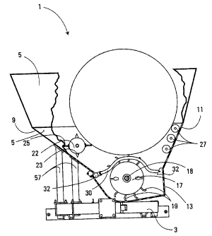
As shown in Figure 1, the bale processor has a
receptacle comprising a processing tub 1 mounted on a
chassis 3. The tube 1 has symmetrical end walls 5 and ~ and
side walls 9 and 11 of differing configurations. A.
CA 02390985 2002-06-19
' 779U3-36
discharge opening l3 is provided at the bottom of side wall
11. A discharge door l2 is pivotally attached to side wall
il above the discharge opening,l3. The discharge door 12 is
raised and lowered to direct the p;roces ed baled material as
it is ejected from the discharge opening 13. The discharge
door 1f can be adjusted manually or actuated through a
hydraulic or electric system of any suitable type known in
the art.
In the embodiment shown in Figure l; side wall 11
l0 is located on the left side of the bale processor. As
discussed below, the processing tub l and the chassis 3 are
designed such that the processing tub can be rotated 180
degrees to position side wall 11 on the right side of the
processor (see Figure 10).
As shown in Figures 3 and 7, the processing tub 1
is sized such that a large square bale, ar; alternatively,
two round bales, may be positioned lengthwise therein for
processing. Typically, an inside width of approximately 7.5
feet (side wall 9 to side wall 11) and in inside length of
at least 10 feet (fromend wall 5 to end wall 7) is
sufficient to'accommodate most'large balers in this manner.
As shown in Figure 2, a disint~grator is mounted
within the processing tub 1. In the embodiment illustrated,
the disintegrator comprises a flail roller 17 extending the
length of the processing tub 1 and mounted in the bottom
thereof. The flail roller l7 is rotatable about its
longitudinal axis such that a series of flails l9 pivotally
mounted thereon extend to engage and separate the baled
material contained within the groves ing tub 1. In the
embodiment shown, the flail roller 17 is slightly offset
from the center of the processing tub 1. The offset of the
CA 02390985 2002-06-19
77903-36
flail roller 17-provides balance to the apparaths due to the
differing configurations of side walls 9 and 11 as well as
the location of a driven feed roller 22 which is discussed
in greater detail below.
Figures 14 and 15 illustrate a design of flai3
roller 17 according to.an embodiment of the invention. As
shown in Figure 14, the flail roller is provided with a
plurality of frail mounts 42. The flail mounts 42 are
spaced longitudinally along the periphery of the flail
roller 17 in two opposing spiral configp.~ations: The flails
19 are pivotally mounted to the flail mounts 42. As shown,
in Figure 15, the flail rolser'has a pivot diameter 44,
being the distance between oppo ing flail mounts 42, and
each flail has a flail length 46: During operation, the
flail roller has a sweep di tance 48 mea ured between the
tips of the two opposing flails 19: For improved
performance in processing speed, throw dis once and
durability of the flail roller 17, the flail roller is
provided with a pivot diame-ter equal to or greater than 15
3/8 inches and a flail length to pivot diameter ratio of
les-s than 0.5. However, the length of the flails'must be of
sufficient length to extend toengage the baled material
positioned in the processing tub 1. The reduction of the
flail length to pivot diameter reduces the change in the
center of gravity of the flail roller 17 which results from
the back slap of the flails 19: The spiral configuration of
the flails 19 on the flail roller 17 also reduces the number
of flails in contact with the baled material at one time.
Thus, the change in the center of gravity resulting from
back slap of the flails 19 is further reduced. In addition,
the reduction in the flail length to pivot diameter ratio
results. in the change in sweep diameter resulting from back
CA 02390985 2003-06-25
slap of the flails 19 being reduced thereby reducing the
effect of back slap on the tip speed of flails 19.
The flail roller 17 is rotated by a power source
(not shown). As shown in Figure 1, the flail roller 17 may
5 be adapted to be detachably connected to a PTO drive of a
tractor. To that end, a flail roller axial rod 18 is
provided on the end of the flail roller 17 and extends
through a set of bearings 21 mounted on end wall 5. As will
be discussed in greater detail below, the opposing end of
10 the flail roller is mounted to end wall 7 in a similar
manner.
In the arrangement shown in Figures 1 and 2,
during operation, the flail roller 17 is rotated in a
clockwise direction (viewed from the rear of the machine).
Accordingly, the flail roller 17 can be connected directly
to the PTO of most tractors. The flail roller axial rod 18
is splined at the end thereof for insertion into a female
splined connection of a standard PTO of a tractor.
Alternative power sources, such as a reversible hydraulic
motor, may be used to drive the flail roller 17 without
departing from the invention in its broadest aspect.
As shown in Figures 1 and 2, the processing tub 1
is provided with a manipulator comprising a single driven
feed roller 22. In the embodiment shown, the driven feed
roller 22 is located above and to the left of the flail
roller 17 (when viewed from the front of the processor) and
extends the length of the processing tub 1. The driven feed
roller 22 is rotatable about its longitudinal axis and has
manipulating members comprising teeth 23 and flanges 25
extending radially therefrom. The side wall 9 extends
CA 02390985 2003-06-25
11A
inwardly and downwardly under the driven feed roller 22
towards the flail roller 17 to direct baled material passing
between the driven feed roller 22 and the side wall 9 into
the flail.roller 17 for disintegration.
As shown in Figure 1, the driven feed roller 22 is
rotated about its longitudinal axis by a reversible
hydraulic motor 33. The driven feed roller 22 is mounted to
end wall 5 by a roller mount 29 secured on the end wall by
an adjustable hanger 36. A set of bearings 31 is positioned
within the roller mount 29 to support the driven feed roller
22 while permitting rotation thereof. The specifications
for the bearings 31 are selected depending upon the typical
load conditions of the driven feed roller 22 during
operation. The adjustable hanger 36 is manually adjusted to
move the roller mount within a rectangular shaped hole 34 in
end wall 5 to move the driven feed roller 22 towards or away
from the flail roller 17 while maintaining the driven feed
roller parallel to the side wall 9. It will be understood
by those skilled in the art that the adjustable hanger could
be replaced by a hydraulic or electric system to move the
driven feed roller 22. As shown in Figure 1, the opposing
end of the driven feed roller is mounted to end wall 7 in an
identical manner as described above.
The hydraulic motor 33 is mounted to a motor mount
35 secured at the upper end thereof to the adjustable hanger
36 and the roller mount 29. The hydraulic motor 33 is
detachably connected to the end of driven feed roller 22.
Specifically, the driven feed roller 22 has a feed roller
axial rod 37 extending from each end thereof. Each feed
roller axial rod 37 has a splined female connection adapted
to releasably receive a splined rotatable shaft 38 of the
CA 02390985 2003-06-25
ZIB
hydraulic motor 33. The motor mount 35 prevents rotation of
the body of hydraulic motor 33 during operation and
maintains the rotatable shaft
CA 02390985 2004-08-31
12
38 engaged with axial rod 37. Alternative connection
assemblies for detachably connecting the hydraulic motor to
the driven feed roller would be known to those skilled in
the art.
As shown in Figures 1 and 2, side wall 11 has a
wall portion slanted inwardly and downwardly towards the
flail roller 17 and is spaced from the driven flail roller
22 such that it provides a passive support means for the
baled material deposited within the processing tub 1. In
the embodiment shown in the drawings, the passive support
means includes a set of three rollers 27 to facilitate
rotation of the baled material contained within the
processing tub 1. It will be understood by a person skilled
in the art that the set of three rollers 27 could be
replaced with a combination of one or more rollers without
departing from the invention in its broadest aspect.
Alternatively, the set or roller 27 can be removed as shown
in Figure 19 and the portion of the inner surface of the
portion of side wall 11 sloping inwardly and downwardly
towards the flail roller would itself provide the passive
support means for the baled crop material. In a further
alternative, a combination of one or more rollers and/or a
portion of the inner surface of the side wall 11 could
provide the passive support means. In a further
alternative, a baffle or one or more non-driven rollers can
CA 02390985 2004-08-31
12A
be provided within the processing tube 1 to provide a
passive support means.
During operation, as the flail roller 17 is
rotated, flails 19 extends radially to engage the baled crop
material positioned between the driven feed roller 22 and
the set of rollers 27, separating it form the baled material
and discharging the disintegrated material through the
CA 02390985 2002-06-19
77903-36
discharge opeW ng 13. As the driven feed roller 22 is
iota ed, the teeth 23 and flanges 25 engage the baled
material contained within the processing tub 1 to rotate the
baled material thereby expo ing different sections thereof
to the flails 19 for disintegration: The set of rollers 27
supports the baled crop material and facilitate rotation
thereof. The hydraulic motor 33 is reversible such that the
driven feed roller 22 can rotate the baled material in both
direc ions.
As shown in Figure 2,a set of feed control rods
30 are provided within the processing tub 1 above the flail
roller 17. The feed control rods 30 are mounted to the side
walls 9 and il of the processing tub 1 arid are axially
spaced along the length of the'processing tub 1 such that;
in operation the flails 19 extend therebetween to engaged
the baled material within the processing tub. The height of
the feed control rods 30-above the flail roller 17 can be
adjusted to alter the rate at which the baled ma erial is
disintegrated and discharged from the proce sing tub 1. The
height is adjus ed by movement''of the location of mounts 32
connecting the feed control rods 30,to the side walls 9 and
11: In one embodiment; a series of mounting locations is
provided on each of the'side walls 9 and 11 which can be
used to mount the feed control rods 30 by use of a locking
pin or other arrangement: Alternatively; the height of the
feed control rods 30 can be-actuated by movement of mounts
32 through a hydraulic-or electric system of any suitable
type known in the art:
The feed control rods 30 minimize clogging and
damage of the flail roller 17 for undisin:tegrated baled
material passing be ween the driven feed roller 22 and, the
v
CA 02390985 2003-06-25
14
passive support means. The feed control rods support any
such material as it is disintegrated by the flails 19. In
addition, as is shown in Figures 4 and 6, the feed control
rods also provide support when bales of different
configurations, such as square bales, are deposited within
the tub processing tub 1 for disintegration.
As shown in Figures 5 and 6, an upper portion 36
of side wall 11 is pivotally attached thereto to facilitate
loading of large square bales widthwise within the
processing tub. As shown in Figure 5, the upper portion 36
of side wall 11 can be lowered to a generally horizontal
position. The large square bale is then positioned within
the processing tub and along the upper portion 36 of side
wall 11. Once the large square bale is in position, the
upper portion 36 of the side wall 11 is raised to its
generally vertical position thereby positioning the bale
within the processing tub 1 for disintegration as shown in
Figure 6. The upper portion 36 of side wall 11 can be
raised or lowered either manually or actuated through a
hydraulic or electric system of the type known in the art.
Alternatively, the upper portion of side wall 9 could be
pivotally mounted thereto to facilitate loading of large
square bales in a similar manner.
As shown in Figure 8, the chassis 3 includes a
hitch 41 mounted at the front thereof and an axle 43
positioned near the rear. Axle 43 has a hollow centre
portion 45 extending transversely across and secured to
chassis 3 and end portions 47 adapted to be inserted therein
on each side of the chassis 3. A ground-engaging wheel 40
is attached to each end portion 47. Each end portion 47 is
adapted to slide axially within the centre portion 45 to
CA 02390985 2002-06-19
77903-36
adjust the width of axle 43. End portions 47 are Lockable
at the desired location by insertion of a locking pin 49
through hopes provided in the center portion 45 and in the
end portions 47. Accordingly,,the axle 43 can be widened to
provide the apparatus with more stability over uneven
terrain or narrowed to facilitate transport along a road or
highway. Furthermore, the axle 43 can b~ widened to improve
stability of the bale while large or more than one bale i's
loaded into the processing tub; 1.
As shown in Figure 9,axle 43 is also provided
with jack mounts 51 to facilita a connection to a jack
assembly (not shown). Each jack mount comprises a square
bracket 53 with a hole 55 in the top bottom thereof. The
square bracket 53 is sized to accept the male connection of
the jack a sembly. A Locking pin (not shown) is inserted
through the holes 55 to maintain the jacl~ assembly connected
during operation. The jack assembly is used to raise a side
of the bale processor such that the widtri of the axle 43 can
be adjusted as set out above.
In a further embodiment shown in Figure 18, the
chassis 3 includes a second-axle 70 positioned between the
front of the chas is and axle 43. The second axle is
provided with a ground engaging wheel' 72 on each end thereof
and includes a hollow center portion 74 and end portions 76
of the type shown;for axle 43 such that the width of the
axle is adjustable for stability and for ease of transport
as described for axle 43. The'second axle 70 is included to
disperse the weight of the processing tub 1 and the baled
material container therein from the axle 43 and hitch 41.
The processing tub 1 is detacha:bly connected to
the chassis 3 such that apparatus can be converted from a
CA 02390985 2002-06-19
~ ' 77903-36
left side di charge arrangement as shown in Figure 1 and 9
to a right side discharge arrangement as shown in Figure 10
or vice-a-versa. The processing tub 1 has front to back
symmetry to facilitate the conversion.
As shown in Figure 9; in the lift side discharge
arrangement, three support legs 57 are bolted to the right
side of the chassis 3 by a U-shaped bolt 59. The
processing tub 1 is connected to the upper part of support'
legs 57 by bolts. Each of end walls 5 arid 7 of the
processing tub 1 are provided with brackets 65 and 67 at the
bottom thereof for connecting the processing tub 1 to the
chassis 3 by U-shaped bolts 69: In the arrangement shown in
Figure 9, as a result of the configura icn of the chassis 3,
bracket 67 on end wall 7 and bracket 65 on end wall 5 are
use to connect the processing tub 1 to the left side of
chassis 3.
As shown in Figure 10, the bale processor is
converted to the right side discharge arrangement by
disconnecting the processing tub l from the chassis 3 and
the support legs 57. The support leg 51 are subsequently
disconnected from the chassis 3 and moved to the left side
of the chassis 3- and secured thereto by LE-shaped bolts 59:
The processing tub 1 i rotated by 180 degrees thereby
positioning side wall 11 on the right side of the chassis.
Side wall 9 is positioned on top of support legs 57 and
secured thereto by bolt . The processing tub 1 is attached
to the right side of chassi 3 by securing bracket 67 on end
wall 5 and bracket 65 on end wall 7 to the right side of the
chas is with U-shaped bolts 69.
Prior to conversion of the apparatus from the lef
side discharge arrangement shown in Figures 9 to the right
CA 02390985 2003-06-25
17
side discharge arrangement shown in Figures 10, the
hydraulic motor 33 and hydraulic motor mount 35 must be
disconnected and the flail drum 17 disconnected from the
power source. Any other hydraulics or other systems would
also be disconnected. Once the processing tub 1 is arranged
in the right side discharge arrangement, as shown in Figure
10, the hydraulic motor 33 and motor mount 35 are connected
to end wall 7 of the processing tub 1 now located at the
front of the chassis 3 in the same manner as discussed
above. As bearings 31 are provided in each roller mount 29,
the driven feed roller does not have to be removed to move
the bearings from one end of the driven feed rollers to the
other.
Any other hydraulics or other systems are then re-
connected to the bale processor once the processing tub 1 is
secured to the chassis. In particular, the power source is
connected to a flail roller axial rod 16 of the flail roller
17 extending through a set of bearings 21 provided in end
wall 7 as shown in Figure 11. However, in the embodiment
shown, in the right side discharge arrangement, the flail
roller 17 must be rotated in a counter-clockwise direction
(when viewed from the rear) during operation. Accordingly,
if the power source rotates in a clockwise direction (i.e. a
PTO of a standard tractor) a rotation conversion device must
be positioned between the power source and the flail roller
17.
In the embodiment shown in Figure 12, the rotation
conversion device comprises a gearbox 71 of the type
commonly used in the industry. The gearbox 71 is positioned
on a dampener 73 to reduce the load on bearings 21 and the
power source due to the weight of the rotation conversion
CA 02390985 2003-06-25
18A
device. In addition, the dampener 73 also serves to absorb
the vibrations and rotation of the gearbox 71 during
acceleration or deceleration, especially during the start-up
and shut down.
The dampener 73 is mounted to the chassis 3 by
brackets 75 secured to the chassis by U-shaped bolts 77. An
upper support 79 having a lip 81 is secured to each of the
brackets 75. A cross support 83 is secured to bottom of
gearbox 71 and extends between brackets 75. The cross
support 83 is mounted at opposing ends thereof to each of
the upper supports 79 by bolts 85 which extend through the
cross support and through lips 81. Upper compression
springs 87 are axially mounted on each of bolts 85 between
the cross supports 83 and the lips 81 of upper supports 79.
Lower compression springs 89 are axially positioned on each
of bolts 85 below lips 81 and maintained in position by a
nut 91.
The upper compression springs 87 are compressed to
exert a slight upper pressure on the gearbox 71 to remove
the stress from the weight of the gearbox from bearings 21
and the power source. Furthermore, during operation, as the
gearbox 71 rotates, opposing upper and lower compressions
springs 87 and 89 co-operate to return the cross support 83,
and thus the gearbox 71, to a level position.
Gearboxes known in the art are typically provided
with a male splined connectors for connecting to input and
output shafts. Accordingly, as shown in Figure 11, flail
roller axial rod 16 is provided with a female splined
connector adapted to receive the male splined connector of
gearbox 71. As shown in Figure 12, a connection arm 93 is
attached to the top of the gearbox 71 at one end thereof and
CA 02390985 2003-06-25
18B
secured to a bracket 95 mounted on the processing tub 1 at
the other end.
CA 02390985 2002-06-19
77903-36
The connection arm prevents the gearbox '~1 from pulling away
from the processing tub 1 and disconnecting from the axial
rod 20:
It will be unders ood by those skilled in the art
that alternative rotation conversion devices, such as a belt
or chain arrangement, may be used without; departing from the
invention in its broadest aspect:
As shown in Figures 8 and 13; an adjustable fork
lift 97 is mounted on the rear of chassis 3 for raising
baled material into the processing tub 1. The adjustability
of the fork lift 97 permits bales of different
configurations to be lifted into the processing tub 1. The
fork Lift 97 is mounted to each side of the chassis 3 by a
mounting bracket 99 secured to:the chassis by U-shaped bolt'
101: A fork lift frame 103 is!pivotallyattached to each of
the mounting brackets 99. Hydraulic cylinders 105 are
pivotally mounted between the fork lif frame 103 and
mounting brackets 99 to raise and lower the fork lift frame.
Two forks 107 are mounted to a bottom cross bar
109 of the fork lift frame 103'by curved brackets 111. The
curved brackets 111 are adapted to slide axially along the
cross bar 109 to adjust the separation between the two forks
107. Each side of the cross bar 109 is provided with a
series of adjustment holes 113 to receive a locking pin 115
which is inserted through a hole 117 provided in he front
of curved brackets 111 to lock' he forks 107 at the desired
location.
As best shown in Figure 13, the length of each
fork 107 is also adjustable. Each fork 107 includes a rear
section 119 and a front section 121 mounted on the rear
CA 02390985 2002-06-19
' 77903-36
section by square bracket 123: The square brackets 123
slide axially along the rear section 119 to adjust the
length of the fork 107. Each square brackets 123 is
provided with holes 125 on opposing side-s thereof and the
5 rear section 119 is provided with a serie of adjustment
hopes 127. The fork 107 can be locked 'at a desired length
by insertion of a locking-pin or bolt through the holes 125
in the square-brackets 123 and one of the adjustment holes
127 in the rear section 119.
10 The front section 121 of'each: fork 107 has a bale
carrier 129 extendinginwnrdly towards the opposing fork.
The bale carriers 129 are the main contact surface for the
baled material and prevent the baled material from, passing
between the forks 107 as it is loaded into the processing
15 tub 1. A bale spear 131 is a3so mounted on: the crow bar
109 between the two forks 107; As the baled material is
positioned on forks 107 and slides: toward cro s bar 109; the
bale spear 131 punctures the baled material to maintain the
bared material in position as it is raised into the
20 processing tub 1.
Figures 16 and 17 illustrate an alternative
embodiment for mounting flail roller 17within the
processing tub 1. The illustrated embodiment is shown with
the processing tub 1 mounted on chassis 3 in the left side
discharge arrangement. As shown in Figure 16, a front
mounting bracket 50 is secured to the front end of chassis 3
by U-shaped bolts 54 adjacent to end wall 5. The front
mounting bracket 50 has a cross-member 58 with a set of
bearings 56 mounted thereon. The front mounting bracket 50;
is designed such that the cross-member 58 is position in
front of a hole provided in end wall 5 of the processing
CA 02390985 2003-06-25
21
tub. The flail roller axial rod 18 extends through the hole
in end wall 5 and through bearings 56, thereby supporting
the front end of flail roller 17. The flail roller axial
rod 18 is sized such that a portion thereof extends from the
bearings 56 for connection to the power source.
As shown in Figure 17, a rear mounting bracket 52
is secured to the rear end of chassis 3 adjacent to end wall
7 by U-shaped bolts 101 which also secures the fork lift
mounting brackets 99 to chassis 3. The rear mounting
bracket 52 has a cross-member 62 with a set of bearings 60
mounted thereon. The rear mounting bracket 50 is designed
such that the cross-member 62 is positioned behind a hole
provided in end wall 7 of the processing tub. The flail
roller axial rod 16 extends through the hole in end wall 7
and through bearings 60, thereby supporting the rear end of
flail roller 17.
For conversion from the left side discharge
arrangement to the right side discharge arrangement, the
front and rear mounting brackets 50 and 52 are disconnected
from the chassis 3. The processing tub 1 is then
disconnected from the chassis 3 and rotated 180 degrees as
discussed above. Once the processing tub 1 is reconnected
to chassis 3, the front and rear mounting brackets 50 and 52
are reconnected to the chassis such that flail roller axial
rod 18 is positioned in bearings 56 and flail roller axial
rod 16 is positioned in bearings 60.
Mounting the flail roller 17 in the manner shown
in Figures 16 and 17 alleviates the stress caused on the
bearings 21 due to vibrations in end walls 5 and 7.