Language selection

Search

Patent 2391057 Summary

Third-party information liability

Some of the information on this Web page has been provided by external sources. The Government of Canada is not responsible for the accuracy, reliability or currency of the information supplied by external sources. Users wishing to rely upon this information should consult directly with the source of the information. Content provided by external sources is not subject to official languages, privacy and accessibility requirements.

Claims and Abstract availability

Any discrepancies in the text and image of the Claims and Abstract are due to differing posting times. Text of the Claims and Abstract are posted:

  • At the time the application is open to public inspection;
  • At the time of issue of the patent (grant).
(12) Patent Application: (11) CA 2391057
(54) English Title: RAILWAY FASTENING CLIP
(54) French Title: ATTACHE DE FIXATION DE VOIE FERREE
Status: Deemed Abandoned and Beyond the Period of Reinstatement - Pending Response to Notice of Disregarded Communication
Bibliographic Data
(51) International Patent Classification (IPC):
  • E01B 09/30 (2006.01)
(72) Inventors :
  • STRYDOM, MARIUS SIGFRIED (South Africa)
  • WEBER, ANDRE CORNELIUS (South Africa)
(73) Owners :
  • MATTHYS, PRETORIUS STRYDOM
(71) Applicants :
  • MATTHYS, PRETORIUS STRYDOM (South Africa)
(74) Agent: LAVERY, DE BILLY, LLP
(74) Associate agent:
(45) Issued:
(86) PCT Filing Date: 2000-11-10
(87) Open to Public Inspection: 2001-05-17
Availability of licence: N/A
Dedicated to the Public: N/A
(25) Language of filing: English

Patent Cooperation Treaty (PCT): Yes
(86) PCT Filing Number: PCT/ZA2000/000212
(87) International Publication Number: ZA2000000212
(85) National Entry: 2002-05-09

(30) Application Priority Data:
Application No. Country/Territory Date
99/7080 (South Africa) 1999-11-12

Abstracts

English Abstract


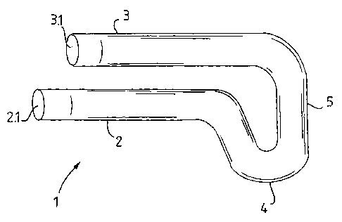
A railway fastening clip for securing a rail comprises an elongate member (1),
formed so as to consist of a first longitudinal leg (2), and a second
longitudinal leg (3), the legs being resiliently connected at one end of the
member, and an ear formation (4) extending transversely beyond the first leg.


French Abstract

L'invention concerne une attache de fixation de voie ferrée servant à fixer un rail, qui comporte un élément (1) allongé, formé de manière à comporter une première branche (2) longitudinale; une deuxième branche (3) longitudinale, les branches étant connectées de manière résiliente à une extrémité de l'élément; et une structure (4) en forme d'oreille s'étendant transversalement au-delà de la première branche.

Claims

Note: Claims are shown in the official language in which they were submitted.

7
CLAIMS
1. A railway fastening clip suitable for securing a rail to a support,
characterised in the clip comprising an elongate member, formed so
as to consist of a first longitudinal leg; and a second longitudinal leg,
the legs being resiliently connected at one end of the member; and
an ear formation extending transversely beyond the first leg.
2. A clip as claimed in claim 1, characterised in the member having an
upper and a lower side, with the end of the first leg proximate to the
connected end being lower than the second leg.
3. A clip as claimed in either claim 1 or claim 2 characterised in that
the free end of each of the legs remote from the connected end of
the member is inclined upwardly.
4. A clip as claimed in claim 3 characterised in the angle of inclination
being less than 40°.
5. A clip as claimed in claim 4 characterised in the angle of inclination
being 4°.
6. A clip as claimed in any of claims 3 to 5 characterised in that the
distance from the end at which the inclination begins is between 5
and 50 mm.
7. A clip as claimed in claim 6, characterised in that the distance from
the end at which the inclination begins is 10 mm.

8
8. A clip as claimed in any of claims 1 to 7 characterised in the ear
formation consisting of a loop section connecting the legs.
9. A clip as claimed in claim 8, characterised in that the part of the
loop defining the end of the member is curved outwardly towards
the upper side of the clip.
10. A clip as claimed in any of the preceding claims characterised in the
length of the first leg extending beyond the second leg.
11. A clip as claimed in any of the preceding claims, characterised in
that the member is manufactured of steel suitable for oil quenching
in production to a hardness of at least 32 Rc.
12. A clip as claimed in claim 11 characterised in that the member is
manufactured of steel suitable for oil quenching in production to a
hardness of 57 Rc.
13. A set of mirrored, left and right orientated clips, each of the left and
right clips comprising an elongate member, formed so as to consist
of a first longitudinal leg, and a second longitudinal leg, which are
resiliently connected at one end of the member, and an ear
formation extending transversely beyond the first leg.
14. The use of a clip, comprising an elongate member, formed so as to
consist of a first longitudinal leg, and a second longitudinal leg,
which are resiliently connected at one end of the member, and an

ear formation extending transversely beyond the first leg, to secure
a rail to a sleeper.

Description

Note: Descriptions are shown in the official language in which they were submitted.


WO 01/34911 CA 02391057 2002-05-09 PCT/ZA00/00212
1
RAILWAY FASTENING CLIP
Technical Field
This invention relates to a railway fastening clip for securing a rail to a
sleeper.
Background Art
The use of railway fastening clips to secure rails to sleepers is well known.
The sleepers used generally in underground mines, as well as those used
in railways in many countries, consist of concrete castings, provided with
steel eye formations to allow the securing of rails thereto using steel clips.
The conventional railway fastening clips used in conjunction with such
sleepers consist of a steel element formed so as to comprise a spiral
including ~threa straight parallel sections, each disposed, in operation, co-
linearly with the rail. In operation, the central straight section passes
through the eye, and one of the other straight sections passes over a
shoulder in the eye while the other exerts a downward force on the base
of the rail, thereby securing it in position. In order to achieve the down
force necessary to secure the rail to the sleeper, the clips have an arched
section which protrudes substantially above the sleeper. The protrusion
of the clips renders them vulnerable to impacts, and problems are thus
experienced with the breakage and displacement of these clips, often
caused by impact from derailed carriages. As clips break, rails become
loose, and the risk of further derailments is increased.

WO 01/34911 CA 02391057 2002-05-09 PCT/ZA00/00212
2
In addition, the cost of producing such clips is relatively high, both in
terms
of the material used and the time and labour expended in forming the
clips.
It is accordingly an object of this invention to provide a railway fastening
clip which will overcome, or at least reduce the above disadvantages.
Disclosure of the Invention
According to a first aspect of the invention, there is provided a railway
fastening clip for securing a rail to a support, the clip comprising an
elongate member, formed so as to consist of a first longitudinal leg; and a
second longitudinal leg, the legs being resiliently connected at one end of
the member; and an ear formation extending transversely beyond the first
leg.
The member may have an upper and a lower side, and the end of the first
leg proximate to the connected end may be lower than the second leg.
The legs may be substantially parallel. Alternatively, the first leg may be
inclined upwardly by up to 20°.
The free end of each of the legs remote from the connected end of the
member may be inclined upwardly. The angle of inclination may be up to
45°, and preferably 4°, and the distance from the end at which
the
inclination begins may be between 5 and 50 mm and preferably
approximately 10 mm.

WO 01/34911 CA 02391057 2002-05-09 PCT/ZA00/00212
3
The ear formation may consist of a loop section connecting the legs.
The part of the loop defining the end of the member may be curved
outwardly towards the upper side of the clip.
The first leg may extend beyond the second leg.
The member may be manufactured of steel suitable for oil quenching in
production to a hardness of at least 32 Rc, and preferably at least 57 Rc.
According to a second aspect of the invention, there is provided a set of
mirrored left and right, substantially as defined above.
According to a third aspect of the invention, there is provided the use of a
clip as defined above for securing a rail in position.
Brief description of the Drawings
The invention will now be described, by way of non-limiting example only,
with reference to the accompanying figures, wherein:
Figure 1 is a side view of a standard steel eye, set into a
concrete sleeper;
Figure 2 is a plan view of a prior art clip;
Figure 3 is an end view of the clip shown in figure 2;

WO 01/34911 CA 02391057 2002-05-09 PCT/ZA00/00212
4
Figure 4 is a plan view of a clip in accordance with the
invention;
Figure 5 is an end view of the clip shown in figure 4;
Figure 6 is a side view of the clip shown in figure 5;
Figure 7 is an end view of an alternative embodiment of
the invention;
Figure 8 is a side view of the clip shown in figure 7; and
Figure 9 is a perspective view of a set of clips in
accordance with the invention, shown here in
operation securing a rail to a sleeper.
Please note that the same reference numerals are used to indicate
corresponding items in the drawings.
Modes for Carrying out the Invention
Figure 1 shows a steel eye (8), such as typically used in railways, inset
into a sleeper (7). The eye (8) includes a shoulder (8.1 ).
A prior art clip, such as generally used in conjunction with such sleepers is
shown in figures 2 and 3 and consists of a steel element (9) formed so as
to comprise a spiral including three straight parallel sections (10-12), each
disposed, in operation, co-linearly with the rail. In operation, the central

WO 01/34911 CA 02391057 2002-05-09 PCT/ZA00/00212
straight section (11 ) passes through the eye (8), and one of the other
straight sections passes over the shoulder (8.1 ) while the other exerts a
downward force on the base of the rail, thereby securing it in position. In
order to achieve the down force necessary to secure the rail to the sleeper
5 (7), the prior art clip has an arched section (13) which protrudes
substantially above the sleeper (7).
A railway fastening clip for securing a rail in accordance with the invention
is shown in figures 3 to 5. The clip comprises an elongate member (1 ),
formed so as to consist of a first longitudinal leg (2), and a second
longitudinal leg (3), the legs being resiliently connected at one end of the
member, and an ear formation (4) extending transversely beyond the first
leg.
The member (1 ) has an upper side (1.1 ) and a lower side (1.2), and the
end of the first leg (2) proximate to the connected end is lower than the
second leg (3).
In one embodiment of the invention, the first leg (2) and the second leg (3)
are substantially parallel. In another embodiment, as shown in figures 6
and 7, the first leg (2) is inclined upwardly by 4°, so as in operation
to
increase the down-force exerted on the rail. It is envisaged that the
inclination could be up to 20°.
In order to prevent accidental displacement of the clip, the free end of
each of the first leg (2) and the second leg (3) remote from the connected
end of the member is also inclined upwardly. The angle of inclination is


WO 01/34911 CA 02391057 2002-05-09 PCT/ZA00/00212
6
and the distance from the end from which the inclination begins is
between 5 and 50 mm and preferably in the region of 10 mm.
The ear formation (4) consists of an loop open (5), connecting the legs.
A part of the loop (5.1 ), defining the end of the member, is slightly curved
outwardly towards the upper side (1.1 ) of the clip.
The length of the first leg (2) extends beyond that of the second leg (3).
The member is manufactured of steel suitable for oil quenching in
production to a hardness of 57 Rc. It is envisaged that a hardness of at
least 32 Rc could suffice.
A mirrored left and right set of clips, substantially as described above is
provided in accordance with the invention.
Figure 9 shows a pair of clips (1 ), as described above, securing a rail (6)
to a sleeper (7) by passing through steel eye formations (8).
It is anticipated that the use of a clip substantially as described above will
overcome or at least reduce the disadvantages stated above.
It will be appreciated that many embodiments of the invention could be
performed without departing from the scope of the invention as defined in
the claims hereunder.

Representative Drawing
A single figure which represents the drawing illustrating the invention.
Administrative Status

2024-08-01:As part of the Next Generation Patents (NGP) transition, the Canadian Patents Database (CPD) now contains a more detailed Event History, which replicates the Event Log of our new back-office solution.

Please note that "Inactive:" events refers to events no longer in use in our new back-office solution.

For a clearer understanding of the status of the application/patent presented on this page, the site Disclaimer , as well as the definitions for Patent , Event History , Maintenance Fee  and Payment History  should be consulted.

Event History

Description Date
Application Not Reinstated by Deadline 2005-11-10
Time Limit for Reversal Expired 2005-11-10
Deemed Abandoned - Failure to Respond to Maintenance Fee Notice 2004-11-10
Letter Sent 2004-05-27
Reinstatement Requirements Deemed Compliant for All Abandonment Reasons 2004-05-17
Deemed Abandoned - Failure to Respond to Maintenance Fee Notice 2003-11-10
Letter Sent 2002-11-07
Inactive: Cover page published 2002-10-29
Inactive: Notice - National entry - No RFE 2002-10-18
Application Received - PCT 2002-08-06
Inactive: Single transfer 2002-08-01
National Entry Requirements Determined Compliant 2002-05-09
Application Published (Open to Public Inspection) 2001-05-17

Abandonment History

Abandonment Date Reason Reinstatement Date
2004-11-10
2003-11-10

Maintenance Fee

The last payment was received on 2004-05-17

Note : If the full payment has not been received on or before the date indicated, a further fee may be required which may be one of the following

  • the reinstatement fee;
  • the late payment fee; or
  • additional fee to reverse deemed expiry.

Patent fees are adjusted on the 1st of January every year. The amounts above are the current amounts if received by December 31 of the current year.
Please refer to the CIPO Patent Fees web page to see all current fee amounts.

Fee History

Fee Type Anniversary Year Due Date Paid Date
Basic national fee - small 2002-05-09
Registration of a document 2002-08-01
MF (application, 2nd anniv.) - small 02 2002-11-12 2002-11-05
Reinstatement 2004-05-17
MF (application, 3rd anniv.) - small 03 2003-11-10 2004-05-17
Owners on Record

Note: Records showing the ownership history in alphabetical order.

Current Owners on Record
MATTHYS, PRETORIUS STRYDOM
Past Owners on Record
ANDRE CORNELIUS WEBER
MARIUS SIGFRIED STRYDOM
Past Owners that do not appear in the "Owners on Record" listing will appear in other documentation within the application.
Documents

To view selected files, please enter reCAPTCHA code :


To view images, click a link in the Document Description column. To download the documents, select one or more checkboxes in the first column and then click the "Download Selected in PDF format (Zip Archive)" or the "Download Selected as Single PDF" button.

List of published and non-published patent-specific documents on the CPD .

If you have any difficulty accessing content, you can call the Client Service Centre at 1-866-997-1936 or send them an e-mail at CIPO Client Service Centre.


Document
Description 
Date
(yyyy-mm-dd) 
Number of pages   Size of Image (KB) 
Representative drawing 2002-10-28 1 6
Claims 2002-05-08 3 67
Abstract 2002-05-08 1 48
Drawings 2002-05-08 5 56
Description 2002-05-08 6 186
Reminder of maintenance fee due 2002-10-20 1 109
Notice of National Entry 2002-10-17 1 192
Courtesy - Certificate of registration (related document(s)) 2002-11-06 1 109
Courtesy - Abandonment Letter (Maintenance Fee) 2004-01-04 1 177
Notice of Reinstatement 2004-05-26 1 166
Courtesy - Abandonment Letter (Maintenance Fee) 2005-01-04 1 175
Reminder - Request for Examination 2005-07-11 1 115
PCT 2002-05-08 11 456
Fees 2002-11-04 1 40
Fees 2004-05-16 1 45