Sélection de la langue

Search

Sommaire du brevet 2391057 

Énoncé de désistement de responsabilité concernant l'information provenant de tiers

Une partie des informations de ce site Web a été fournie par des sources externes. Le gouvernement du Canada n'assume aucune responsabilité concernant la précision, l'actualité ou la fiabilité des informations fournies par les sources externes. Les utilisateurs qui désirent employer cette information devraient consulter directement la source des informations. Le contenu fourni par les sources externes n'est pas assujetti aux exigences sur les langues officielles, la protection des renseignements personnels et l'accessibilité.

Disponibilité de l'Abrégé et des Revendications

L'apparition de différences dans le texte et l'image des Revendications et de l'Abrégé dépend du moment auquel le document est publié. Les textes des Revendications et de l'Abrégé sont affichés :

  • lorsque la demande peut être examinée par le public;
  • lorsque le brevet est émis (délivrance).
(12) Demande de brevet: (11) CA 2391057
(54) Titre français: ATTACHE DE FIXATION DE VOIE FERREE
(54) Titre anglais: RAILWAY FASTENING CLIP
Statut: Réputée abandonnée et au-delà du délai pour le rétablissement - en attente de la réponse à l’avis de communication rejetée
Données bibliographiques
(51) Classification internationale des brevets (CIB):
  • E01B 09/30 (2006.01)
(72) Inventeurs :
  • STRYDOM, MARIUS SIGFRIED (Afrique du Sud)
  • WEBER, ANDRE CORNELIUS (Afrique du Sud)
(73) Titulaires :
  • MATTHYS, PRETORIUS STRYDOM
(71) Demandeurs :
  • MATTHYS, PRETORIUS STRYDOM (Afrique du Sud)
(74) Agent: LAVERY, DE BILLY, LLP
(74) Co-agent:
(45) Délivré:
(86) Date de dépôt PCT: 2000-11-10
(87) Mise à la disponibilité du public: 2001-05-17
Licence disponible: S.O.
Cédé au domaine public: S.O.
(25) Langue des documents déposés: Anglais

Traité de coopération en matière de brevets (PCT): Oui
(86) Numéro de la demande PCT: PCT/ZA2000/000212
(87) Numéro de publication internationale PCT: ZA2000000212
(85) Entrée nationale: 2002-05-09

(30) Données de priorité de la demande:
Numéro de la demande Pays / territoire Date
99/7080 (Afrique du Sud) 1999-11-12

Abrégés

Abrégé français

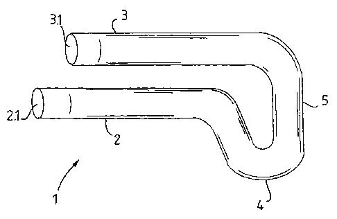
L'invention concerne une attache de fixation de voie ferrée servant à fixer un rail, qui comporte un élément (1) allongé, formé de manière à comporter une première branche (2) longitudinale; une deuxième branche (3) longitudinale, les branches étant connectées de manière résiliente à une extrémité de l'élément; et une structure (4) en forme d'oreille s'étendant transversalement au-delà de la première branche.


Abrégé anglais


A railway fastening clip for securing a rail comprises an elongate member (1),
formed so as to consist of a first longitudinal leg (2), and a second
longitudinal leg (3), the legs being resiliently connected at one end of the
member, and an ear formation (4) extending transversely beyond the first leg.

Revendications

Note : Les revendications sont présentées dans la langue officielle dans laquelle elles ont été soumises.


7
CLAIMS
1. A railway fastening clip suitable for securing a rail to a support,
characterised in the clip comprising an elongate member, formed so
as to consist of a first longitudinal leg; and a second longitudinal leg,
the legs being resiliently connected at one end of the member; and
an ear formation extending transversely beyond the first leg.
2. A clip as claimed in claim 1, characterised in the member having an
upper and a lower side, with the end of the first leg proximate to the
connected end being lower than the second leg.
3. A clip as claimed in either claim 1 or claim 2 characterised in that
the free end of each of the legs remote from the connected end of
the member is inclined upwardly.
4. A clip as claimed in claim 3 characterised in the angle of inclination
being less than 40°.
5. A clip as claimed in claim 4 characterised in the angle of inclination
being 4°.
6. A clip as claimed in any of claims 3 to 5 characterised in that the
distance from the end at which the inclination begins is between 5
and 50 mm.
7. A clip as claimed in claim 6, characterised in that the distance from
the end at which the inclination begins is 10 mm.

8
8. A clip as claimed in any of claims 1 to 7 characterised in the ear
formation consisting of a loop section connecting the legs.
9. A clip as claimed in claim 8, characterised in that the part of the
loop defining the end of the member is curved outwardly towards
the upper side of the clip.
10. A clip as claimed in any of the preceding claims characterised in the
length of the first leg extending beyond the second leg.
11. A clip as claimed in any of the preceding claims, characterised in
that the member is manufactured of steel suitable for oil quenching
in production to a hardness of at least 32 Rc.
12. A clip as claimed in claim 11 characterised in that the member is
manufactured of steel suitable for oil quenching in production to a
hardness of 57 Rc.
13. A set of mirrored, left and right orientated clips, each of the left and
right clips comprising an elongate member, formed so as to consist
of a first longitudinal leg, and a second longitudinal leg, which are
resiliently connected at one end of the member, and an ear
formation extending transversely beyond the first leg.
14. The use of a clip, comprising an elongate member, formed so as to
consist of a first longitudinal leg, and a second longitudinal leg,
which are resiliently connected at one end of the member, and an

ear formation extending transversely beyond the first leg, to secure
a rail to a sleeper.

Description

Note : Les descriptions sont présentées dans la langue officielle dans laquelle elles ont été soumises.

WO 01/34911 CA 02391057 2002-05-09 PCT/ZA00/00212
1
RAILWAY FASTENING CLIP
Technical Field
This invention relates to a railway fastening clip for securing a rail to a
sleeper.
Background Art
The use of railway fastening clips to secure rails to sleepers is well known.
The sleepers used generally in underground mines, as well as those used
in railways in many countries, consist of concrete castings, provided with
steel eye formations to allow the securing of rails thereto using steel clips.
The conventional railway fastening clips used in conjunction with such
sleepers consist of a steel element formed so as to comprise a spiral
including ~threa straight parallel sections, each disposed, in operation, co-
linearly with the rail. In operation, the central straight section passes
through the eye, and one of the other straight sections passes over a
shoulder in the eye while the other exerts a downward force on the base
of the rail, thereby securing it in position. In order to achieve the down
force necessary to secure the rail to the sleeper, the clips have an arched
section which protrudes substantially above the sleeper. The protrusion
of the clips renders them vulnerable to impacts, and problems are thus
experienced with the breakage and displacement of these clips, often
caused by impact from derailed carriages. As clips break, rails become
loose, and the risk of further derailments is increased.

WO 01/34911 CA 02391057 2002-05-09 PCT/ZA00/00212
2
In addition, the cost of producing such clips is relatively high, both in
terms
of the material used and the time and labour expended in forming the
clips.
It is accordingly an object of this invention to provide a railway fastening
clip which will overcome, or at least reduce the above disadvantages.
Disclosure of the Invention
According to a first aspect of the invention, there is provided a railway
fastening clip for securing a rail to a support, the clip comprising an
elongate member, formed so as to consist of a first longitudinal leg; and a
second longitudinal leg, the legs being resiliently connected at one end of
the member; and an ear formation extending transversely beyond the first
leg.
The member may have an upper and a lower side, and the end of the first
leg proximate to the connected end may be lower than the second leg.
The legs may be substantially parallel. Alternatively, the first leg may be
inclined upwardly by up to 20°.
The free end of each of the legs remote from the connected end of the
member may be inclined upwardly. The angle of inclination may be up to
45°, and preferably 4°, and the distance from the end at which
the
inclination begins may be between 5 and 50 mm and preferably
approximately 10 mm.

WO 01/34911 CA 02391057 2002-05-09 PCT/ZA00/00212
3
The ear formation may consist of a loop section connecting the legs.
The part of the loop defining the end of the member may be curved
outwardly towards the upper side of the clip.
The first leg may extend beyond the second leg.
The member may be manufactured of steel suitable for oil quenching in
production to a hardness of at least 32 Rc, and preferably at least 57 Rc.
According to a second aspect of the invention, there is provided a set of
mirrored left and right, substantially as defined above.
According to a third aspect of the invention, there is provided the use of a
clip as defined above for securing a rail in position.
Brief description of the Drawings
The invention will now be described, by way of non-limiting example only,
with reference to the accompanying figures, wherein:
Figure 1 is a side view of a standard steel eye, set into a
concrete sleeper;
Figure 2 is a plan view of a prior art clip;
Figure 3 is an end view of the clip shown in figure 2;

WO 01/34911 CA 02391057 2002-05-09 PCT/ZA00/00212
4
Figure 4 is a plan view of a clip in accordance with the
invention;
Figure 5 is an end view of the clip shown in figure 4;
Figure 6 is a side view of the clip shown in figure 5;
Figure 7 is an end view of an alternative embodiment of
the invention;
Figure 8 is a side view of the clip shown in figure 7; and
Figure 9 is a perspective view of a set of clips in
accordance with the invention, shown here in
operation securing a rail to a sleeper.
Please note that the same reference numerals are used to indicate
corresponding items in the drawings.
Modes for Carrying out the Invention
Figure 1 shows a steel eye (8), such as typically used in railways, inset
into a sleeper (7). The eye (8) includes a shoulder (8.1 ).
A prior art clip, such as generally used in conjunction with such sleepers is
shown in figures 2 and 3 and consists of a steel element (9) formed so as
to comprise a spiral including three straight parallel sections (10-12), each
disposed, in operation, co-linearly with the rail. In operation, the central

WO 01/34911 CA 02391057 2002-05-09 PCT/ZA00/00212
straight section (11 ) passes through the eye (8), and one of the other
straight sections passes over the shoulder (8.1 ) while the other exerts a
downward force on the base of the rail, thereby securing it in position. In
order to achieve the down force necessary to secure the rail to the sleeper
5 (7), the prior art clip has an arched section (13) which protrudes
substantially above the sleeper (7).
A railway fastening clip for securing a rail in accordance with the invention
is shown in figures 3 to 5. The clip comprises an elongate member (1 ),
formed so as to consist of a first longitudinal leg (2), and a second
longitudinal leg (3), the legs being resiliently connected at one end of the
member, and an ear formation (4) extending transversely beyond the first
leg.
The member (1 ) has an upper side (1.1 ) and a lower side (1.2), and the
end of the first leg (2) proximate to the connected end is lower than the
second leg (3).
In one embodiment of the invention, the first leg (2) and the second leg (3)
are substantially parallel. In another embodiment, as shown in figures 6
and 7, the first leg (2) is inclined upwardly by 4°, so as in operation
to
increase the down-force exerted on the rail. It is envisaged that the
inclination could be up to 20°.
In order to prevent accidental displacement of the clip, the free end of
each of the first leg (2) and the second leg (3) remote from the connected
end of the member is also inclined upwardly. The angle of inclination is


WO 01/34911 CA 02391057 2002-05-09 PCT/ZA00/00212
6
and the distance from the end from which the inclination begins is
between 5 and 50 mm and preferably in the region of 10 mm.
The ear formation (4) consists of an loop open (5), connecting the legs.
A part of the loop (5.1 ), defining the end of the member, is slightly curved
outwardly towards the upper side (1.1 ) of the clip.
The length of the first leg (2) extends beyond that of the second leg (3).
The member is manufactured of steel suitable for oil quenching in
production to a hardness of 57 Rc. It is envisaged that a hardness of at
least 32 Rc could suffice.
A mirrored left and right set of clips, substantially as described above is
provided in accordance with the invention.
Figure 9 shows a pair of clips (1 ), as described above, securing a rail (6)
to a sleeper (7) by passing through steel eye formations (8).
It is anticipated that the use of a clip substantially as described above will
overcome or at least reduce the disadvantages stated above.
It will be appreciated that many embodiments of the invention could be
performed without departing from the scope of the invention as defined in
the claims hereunder.

Dessin représentatif
Une figure unique qui représente un dessin illustrant l'invention.
États administratifs

2024-08-01 : Dans le cadre de la transition vers les Brevets de nouvelle génération (BNG), la base de données sur les brevets canadiens (BDBC) contient désormais un Historique d'événement plus détaillé, qui reproduit le Journal des événements de notre nouvelle solution interne.

Veuillez noter que les événements débutant par « Inactive : » se réfèrent à des événements qui ne sont plus utilisés dans notre nouvelle solution interne.

Pour une meilleure compréhension de l'état de la demande ou brevet qui figure sur cette page, la rubrique Mise en garde , et les descriptions de Brevet , Historique d'événement , Taxes périodiques et Historique des paiements devraient être consultées.

Historique d'événement

Description Date
Demande non rétablie avant l'échéance 2005-11-10
Le délai pour l'annulation est expiré 2005-11-10
Réputée abandonnée - omission de répondre à un avis sur les taxes pour le maintien en état 2004-11-10
Lettre envoyée 2004-05-27
Exigences de rétablissement - réputé conforme pour tous les motifs d'abandon 2004-05-17
Réputée abandonnée - omission de répondre à un avis sur les taxes pour le maintien en état 2003-11-10
Lettre envoyée 2002-11-07
Inactive : Page couverture publiée 2002-10-29
Inactive : Notice - Entrée phase nat. - Pas de RE 2002-10-18
Demande reçue - PCT 2002-08-06
Inactive : Transfert individuel 2002-08-01
Exigences pour l'entrée dans la phase nationale - jugée conforme 2002-05-09
Demande publiée (accessible au public) 2001-05-17

Historique d'abandonnement

Date d'abandonnement Raison Date de rétablissement
2004-11-10
2003-11-10

Taxes périodiques

Le dernier paiement a été reçu le 2004-05-17

Avis : Si le paiement en totalité n'a pas été reçu au plus tard à la date indiquée, une taxe supplémentaire peut être imposée, soit une des taxes suivantes :

  • taxe de rétablissement ;
  • taxe pour paiement en souffrance ; ou
  • taxe additionnelle pour le renversement d'une péremption réputée.

Les taxes sur les brevets sont ajustées au 1er janvier de chaque année. Les montants ci-dessus sont les montants actuels s'ils sont reçus au plus tard le 31 décembre de l'année en cours.
Veuillez vous référer à la page web des taxes sur les brevets de l'OPIC pour voir tous les montants actuels des taxes.

Historique des taxes

Type de taxes Anniversaire Échéance Date payée
Taxe nationale de base - petite 2002-05-09
Enregistrement d'un document 2002-08-01
TM (demande, 2e anniv.) - petite 02 2002-11-12 2002-11-05
Rétablissement 2004-05-17
TM (demande, 3e anniv.) - petite 03 2003-11-10 2004-05-17
Titulaires au dossier

Les titulaires actuels et antérieures au dossier sont affichés en ordre alphabétique.

Titulaires actuels au dossier
MATTHYS, PRETORIUS STRYDOM
Titulaires antérieures au dossier
ANDRE CORNELIUS WEBER
MARIUS SIGFRIED STRYDOM
Les propriétaires antérieurs qui ne figurent pas dans la liste des « Propriétaires au dossier » apparaîtront dans d'autres documents au dossier.
Documents

Pour visionner les fichiers sélectionnés, entrer le code reCAPTCHA :


Pour visualiser une image, cliquer sur un lien dans la colonne description du document. Pour télécharger l'image (les images), cliquer l'une ou plusieurs cases à cocher dans la première colonne et ensuite cliquer sur le bouton "Télécharger sélection en format PDF (archive Zip)" ou le bouton "Télécharger sélection (en un fichier PDF fusionné)".

Liste des documents de brevet publiés et non publiés sur la BDBC .

Si vous avez des difficultés à accéder au contenu, veuillez communiquer avec le Centre de services à la clientèle au 1-866-997-1936, ou envoyer un courriel au Centre de service à la clientèle de l'OPIC.


Description du
Document 
Date
(aaaa-mm-jj) 
Nombre de pages   Taille de l'image (Ko) 
Dessin représentatif 2002-10-28 1 6
Revendications 2002-05-08 3 67
Abrégé 2002-05-08 1 48
Dessins 2002-05-08 5 56
Description 2002-05-08 6 186
Rappel de taxe de maintien due 2002-10-20 1 109
Avis d'entree dans la phase nationale 2002-10-17 1 192
Courtoisie - Certificat d'enregistrement (document(s) connexe(s)) 2002-11-06 1 109
Courtoisie - Lettre d'abandon (taxe de maintien en état) 2004-01-04 1 177
Avis de retablissement 2004-05-26 1 166
Courtoisie - Lettre d'abandon (taxe de maintien en état) 2005-01-04 1 175
Rappel - requête d'examen 2005-07-11 1 115
PCT 2002-05-08 11 456
Taxes 2002-11-04 1 40
Taxes 2004-05-16 1 45