Note: Descriptions are shown in the official language in which they were submitted.
WO 01/36025 CA 02391412 2002-05-13 PCT/US00/30822
-1-
LOCKING NEEDLE PROTECTOR
The present invention relates generally to protective
devices for used medical needles to prevent inadvertent
user contact with such needles. The protective devices
(i.e., needle protectors) of the present invention may be
incorporated into a disposable plastic tubing and container
set used in the collection and processing of a biological
fluid such as blood.
BACKGROUND OF THE INVENTION
Needles are used in a wide variety of procedures in
the medical field. For example, needles are commonly used
to administer fluids, such as intravenous solution,
medication, blood components and the like to patients, as
well as to withdraw fluids, such as blood or other fluids
from patients or donors. One very common application for
needles is in collecting blood from a donor.
Withdrawing blood from a donor typically involves
inserting a needle into the donor's vein and withdrawing
blood from the donor through the needle and associated
plastic tubing into a collection bag or blood processing
device. Typically, the needle, tubing and containers make
up a blood processing set which is disposed of after a
single use.
The presence of blood-borne pathogens that may lead
to serious medical conditions such as hepatitis, AIDS and
other diseases have given rise to increased concern for
accidental needle puncture after a needle is withdrawn from
a patient's or donor's arm. The concern includes
withdrawal of the needle and the possibility of an
WO 01/36025 CA 02391412 2002-05-13 PCT/US00/30822
-2-
accidental needle stick to the technician or nurse, as well
as the safe disposal of the used needle. For this reason,
the medical field has developed devices that allow for the
safe withdrawal and storage of the used needles.
Some of the early needle protectors were in the form
of a cap that was placed over the needle. The caps
typically included a flat plate or shield, which extended
radially outwardly near the opening of the cap . The shield
protected the technician's fingers from the needle during
placement of the cap over the needle. A needle protector
of this type is described in U.S. Patent No. 4,840,618.
More recently, in the field of blood processing and/or
collection, the needle protectors have been incorporated
into the disposable tubing and container sets used to
collect and process the blood. For example, U.S. Patent
No. 5,833,670 discloses a sheath adapted to be slidably
supported on the tubing of the disposable processing set.
The sheath is open at its distal and proximal ends with the
tubing extending through the open ends of the protective
sheath. After collection, the sheath is slidably moved
over the needle and/or the needle is completely retracted
within the sheath.
U. S . Patent No . 5 , 772 , 63 8 discloses a needle protector
having slotted side walls (to receive a winged needle) and
an end wall. The protector is slidably mounted on the
tubing of the disposable processing set. As the protector
is slidably moved forward over the needle (and the needle
is withdrawn into the protector) the end wall causes the
needle and the hub to be held in the sheath in an acute
angle to the top wall with the needle tip positioned
against the underside of the top wall.
While these needle protectors have generally worked
satisfactorily, efforts continue to provide further
improvements in the area of needle protection.
WO 01/36025 CA 02391412 2002-05-13 PCT/US00/30822
-3-
SUNJHiARY OF THE INVENTION
The present invention is generally directed to a
needle protector having an elongated housing that has a
distal end and a proximal end. The housing defines a
needle-receiving compartment that restricts unintentional
contact with the needle. The housing further includes an
opening at each of the proximal and distal ends and is
adapted to receive a needle through the opening at the
distal end. The housing includes a portion that is
depressable to a substantially fixed position to capture
a needle within the housing.
In a further aspect of the present invention, the
needle protector may include a depressable top wall
hingedly attached to the housing at the proximal end. In
another aspect of the present invention, the needle
protector may include at least a pair of facing side walls .
The side walls may be adapted to maintain the top wall in
the depressed position. In another aspect of the present
invention, the needle protector may include a detent
extending from the interior surface of at least one of the
walls, such as the top wall, to immobilize the retracted
needle.
The present invention is also directed to a needle and
a needle protector assembly. The assembly includes a
needle mounted on a hub and a length of tubing having one
end attached to the hub, the tubing defining a flow path
for a biological fluid. The assembly further includes a
housing having a distal end and a proximal end. The
housing defines a needle-receiving compartment that
restricts unintentional contact with the needle. The
housing may also include an opening at each of the proximal
and distal ends. The length of tubing extends through at
least the opening at the proximal end and allows for
movement of the housing and tubing relative to one another.
WO 01/36025 CA 02391412 2002-05-13 PCT/CTS00/30822
-4-
The housing includes a portion that is depressable to a
substantially fixed position to capture a needle within the
housing.
BRIEF DESCRIPTION OF THE DRAWINGS
FIG. 1 is a plan view of a disposable tubing and
container set with a needle protector embodying the present
invention ;
FIG. 2 is a perspective view from the distal end
of
a needle
protector
embodying
the present
invention
located
on a tubing
segment,
with a
needle
at the
end of
a tubing
segment;
FIG. 3 is a perspective view from the proximal end
of
the needl e protector of Fig. 2;
FIG. 4 is a perspective view of the needle protector
of Fig. 2 with the needle in a partially retracted
position;
FIG. 5 is a perspective view of the needle protector
of Fig. 2 with the needle in a completely retracted
position;
FIG. 6 is a cross-sectional side view of the needle
protector of Fig. 5 taken along lines 6-6;
FIG. 6A is a cross-sectional side view of the needle
protector of Fig. 5 as the needle is being retracted into
the needl e-receiving compartment of the housing;
FIG. 7 is a perspective view of the needle protector
with the
needle
disposed
in a completely
retracted
position
and the op wall detached from the housing at the distal
t
end;
FIG. 8 is a distal end view of the needle protector
of Fig. 5 with the needle disposed in a completely
retracted position;
FIG. 9 is a distal end view of the needle protector
of FIG. with the top wall depressed over the needle;
8
WO 01/36025 CA 02391412 2002-05-13 pCT/US00/30822
-5-
FIG. 10 is a perspective view of the needle protector
(with the top depressed) placed within a tube holder of the
disposable processing set; and
FIG. 11 is an end view of the needle protector
disposed within the tube holder of Fig. 10.
DETAILED DESCRIPTION OF THE DRAWINGS
The needle protector of the present invention will be
described below in the context of its preferred use,
namely, as a needle protector for a needle that is part of
a disposable tubing and container set intended for the
collection and processing of blood. Of course, it will be
understood that the needle protector of the present
invention is not limited to use with a disposable tubing
and cor_=ainer set or even to use in the medical field. The
needle protector of the present invention may be used in
any other application where a needle that is attached to
a length of tubing is employed.
Also, as used herein, the term "needle" refers to any
elongated member having a sharpened tip for puncturing or
piercing. The term "needle" is not limited to traditional
venipuncture needles which are typically made of stainless
steel and are relatively small in diameter. Although the
term "needle" includes such venipuncture needles, it also
includes piercing members made from other materials, such
as plastic, and includes cannulas, coupling devices and the
like.
Turning now to the drawings , Fig . 1 shows a disposable
tubing and container set i0, which is particularly suitable
for use in the processing of blood from a donor 11. The
illustrated disposable set 10 may include a needle such as
venipuncture needle 12, and a plastic tubing segment 16
attached to needle 12 and extending from needle 12 to a
plastic, blood collection container 18. The disposable
WO 01/36025 CA 02391412 2002-05-13 PCT/LTS00/30822
-6-
blood processing set 10 may include a single blood
collection container 18, or more commonly, as shown in Fig.
1, may include a primary container and additional,
integrally attached containers 20 and 22, as is well known
in the field.
Briefly, during use, primary container 18 (sometimes
referred to as the donor bag) receives whole blood from
donor 11 through tubing 16 and needle 12. Container 18
typically includes a suitable anticoagulant such as citrate
phosphate dextrose (CPD), citrate phosphate dextrose
adenine (CPDA) or acid citrate dextrose (ACD).
Containers 20 and 22 may be attached to primary container
18 by integrally attached transfer tubing 24 and 26.
Containers 20 and 22 are provided to receive blood
components such as, but not limited to, red blood cells and
plasma that have been separated from whole blood. The
methods and disposable sets for practicing such methods are
well known and will not be discussed here. They are,
however, described in U.S. Patent Nos. 4,222,379 and
5,445,629, which are incorporated by reference herein.
Disposable processing set 10 may also include an
integrally attached sampling system 28. Sampling system
28 includes a sampling pouch 30, a frangible connector 34
and a tube holder 32 for receiving a sampling vial. A
sampling system 28 of the type shown in Fig. 1 (and the
method of sampling) is described in co-pending U.S.
Application Serial No. 09/364,628, filed July 29, 1999
which is also incorporated by reference herein.
As shown in Fig. 1, blood processing set 10 also
includes a needle protector 40 embodying the present
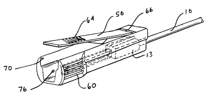
invention. Turning now to Figs. 2 and 3, the needle
protector 40 of the present invention includes, in general,
an elongated housing 42. Housing 42 has a distal end 44
and a proximal end 46. Housing 42 further includes an
WO 01/36025 CA 02391412 2002-05-13 PCT/US00/30822
_7_
opening 48 at the distal end 44 and an opening 50 at
proximal end 46. As shown in Figs. 2 and 3, the tubing
segment 16 extends through the open ends 48 and 50 of
housing 42. A needle 12 mounted on hub 13 is attached to
tubing 16. Needle 12 may be enclosed within cover 15 which
is removed at the time of use.
In a preferred embodiment housing 42 is defined by
side walls 52 and 54, top wall 56, and bottom wall 58 to
provide a needle-receiving compartment. As shown in Fig.
2 and 3, side walls 52 and 54 may include flanges 53 at the
distal end 44 of housing 42. In an alternative embodiment,
housing 42 may be defined by top wall 56 and a continuous,
arcuate wall that extends from one side of top wall 56 to
the other side. In another alternative embodiment, housing
42 may be defined by a top wall and two side walls to
provide, for example, a needle-receiving compartment with
a substantially triangular cross-section.
Housing 42 may be made by casting, injection molding
or other techniques known to those of skill in the art.
Housing 42 may be made of any material suitably rigid and
puncture resistant and suitable for use in the medical
field. For example, housing 42 may be made of any
thermoplastic material that can be sterilized by known
sterilization techniques including, but not limited to
autoclaving, gamma radiation, or an electron beam
radiation. Housing 42 may be made (by, for example,
molding) of a polyolefin material, such as, most
preferably, polypropylene. Other suitable materials may
include polyethylene, such as high density polyethylene,
polyacetal and polycarbonate. It will be understood that
the housing may also be made of blends of two or more
materials, including the materials identified above.
As shown in Figs. 2-4, housing 40 includes gripping
surfaces in the form of raised ribs 60 and 62 on the outer
WO 01/36025 CA 02391412 2002-05-13 pCT/US00/30822
_8_
surfaces of side walls 52 and 54, and on the outer surface
of the top wall 56. Gripping surfaces 60, 62 and 64 may
be formed during the molding process in ways that will be
understood by those of skill in the art. Where housing
includes bottom wall 58, such wall 58 may have a
substantially smooth exterior surface.
Turning briefly to Fig. 7, top wall 56 is hinged to
the housing at proximal end 46. Hinge 66 may be a section
of top wall 56 which has a reduced thickness relative to
the remainder of top wall 56. For example, whereas top
wall 56 (or any other wall housing 42) may have a thickness
of approximately 1.0 to 1.5 mm, the thickness of hinge 66
may be approximately 0.2 to 0.4 mm.
Top wall 56 may be attached to housing 42 at distal
end 44 by frangible tabs or webs 70. By depressing distal
end 44 and top wall 56, frangible tabs or webs 70 may be
broken and, as more specifically shown by the broken lines
in Fig. 6, top wall 56 may be depressed to a location
between side walls 52 and 54 and over a needle retracted
within housing 42. In a preferred embodiment, tabs or webs
70 are thin sections of plastic, molded with housing 42.
Also, in the event that needle 12 becomes inadvertently
fully retracted and captured within housing 42 prior to its
use, breakable tabs allow top wall 56 to be released from
housing 42 and permit withdrawal of needle 12 for its
intended use. Thus, an unused needle and needle protector
assembly or unused disposable processing set where needle
12 is fully retracted would still be usable.
The needle protector may be slidably moved over tubing
16 and over needle 12 and hub 13. Needle 12 with needle
hub 13 may be either partially or completely retracted
within the housing 42 through distal opening 48. For
example, Fig. 4 shows the needle in a partially retracted
position. Most typically, needle 12 is inserted into the
WO 01/36025 CA 02391412 2002-05-13 PCT/US00/30822
_g_
donor's vein such that rib 13a on hub 13 is turned away
from the donor's arm, as shown in Fig. 4. However, during
blood collection, it is not uncommon for the nurse or
technician to rotate the needle 12 to, for example, improve
blood flow, and change the orientation of hub 13. Thus,
hub may be rotated 90° (in either direction) or 180°
relative to the position shown in Fig. 4. It is also not
uncommon for the nurse or technician to rotate housing 42
relative to the needle 12 and hub 13. For example, the
technician may rotate housing 42 so that top wall 56 rests
on and is in contact with the donor's arm. This provides
a smooth surface ( i . a . , bottom wall 58 ) over which adhesive
tape, used to hold housing 42 in place on the donor's arm,
may be affixed. Accordingly, distal opening 48 should have
a height and width sufficient to receive needle 12 and hub
13 regardless of whether hub 13 is retracted in its typical
orientation or any of the above described orientations.
As shown in Fig. 2, opening 48 may be wider near the
top wall and, preferably, tapers to a narrower width near
bottom wall 58. A gradual, tapered transition from greater
to smaller width of opening 48 is preferred to allow for
easier depression of top wall 56, as described below. In
any event, distal opening 48 near bottom wall 58 should be
at least as wide and, preferably slightly wider, than the
widest portion of hub 13 which is designated by reference
numeral 13x in, for example, Fig. 4.
Needle 12 with needle hub 13 may be completely
retracted within housing 42 as shown in Figs. 5 and 6.
Housing 42 allows for capture of needle 12 within the
protector and for further shielding the retracted needle
12 from the outside environment. For example, as shown in
Fig. 5, needle 12 (with hub 13) may be fully retracted and
more permanently captured by the needle protector. As
further shown in Figs. 5 and 6, top wall 56 may include a
WO 01/36025 CA 02391412 2002-05-13 PCT/US00/30822
-10-
detent 74 which depends from the inner surface of top wall
56. Of course, side walls 52, 54 and bottom wall 58 may
also include detents or the like for retaining hub 13.
In any event, as housing 42 is slidably moved over
needle 12 and needle 12 is retracted into housing 42,
needle hub 13 pushes detent 74 causing top wall 56 to
slightly flex upwardly as shown in Fig. 6A. The degree of
flexing will depend on whether, during retraction, hub 13
is in its normal orientation or turned 90° or 180° as
described above. Once hub 13 has moved beyond detent 74,
top wall 56 returns to its position and detent 74 prevents
further forward movement (i.e., movement toward the distal
end) of the needle 12. Of course, movement of the needle
assembly in a rearward fashion is also prevented if the hub
13 has a larger cross sectional area than the opening 50
at proximal end 46. In any event, the needle 12 is
immobilized and reduces the risk that the technician will
be injured by an accidental needle stick. Housing 42 is
longer than the needle and hub so that distal end 44 of
housing is spaced far enough beyond the needle end to
prevent inadvertent contact with the technician or other
medical personnel.
To further secure the needle 12, top wall 56 may be
depressed and "locked" over retracted needle 12. By
applying pressure to top wall 56 (at, for example, gripping
surfaces 64), tabs or webs 70 may be broken to allow
depression of top wall 56. In a preferred embodiment, top
wall 56 may be maintained and locked in this position.
Thus, housing 42 may include means for capturing top wall
and retaining top wall 56 in the depressed and locked
position. In one embodiment, the capturing means may be
bumps or protrusions 76 on the interior surfaces of side
walls 52 and 54, as shown in Fig. 7. The protrusions 76
may be formed during the molding process or may be
WO 01/36025 CA 02391412 2002-05-13 PCT/C1S00/30822
-11-
separately attached to the interior wall surfaces. As top
wall 56 is depressed past protrusions 76, an audible
"click" may be heard which assures the technician that top
wall 56 is locked in the depressed position.
For further safety, where needle protector 40 of the
present invention is part of a disposable tubing and
container set such as the set shown in Fig . 1 and described
in detail in U.S. Patent Application Serial No. 09/364,628,
filed July 29, 1999 which has been incorporated by
reference. With reference to Fig. 10, housing 42 with the
needle 12 disposed therein (not shown) may be placed inside
a tube holder 32 for disposal with the entire disposable
set. Housing 42 may be inserted into open tube holder 32,
distal end 44 first. Housing 42 is advanced through the
open holder so that the distal end 44 exits through the
opposite open end of holder 32. Removal of housing 42 from
holder 32 is, in large part, prevented by flanges 53 which
extend beyond the side walls 32a of holder 32 as shown in
Figs. 10 and 11. In other words, distal end 44 (and, more
particularly, flanges 53) of housing 42 is held by the side
walls 32a of the holder.
The present invention has been described in accordance
with the preferred embodiment. However, it will be
understood that minor variations to the embodiments shown
herein may be made without departing from the present
invention which is specifically set forth in the appended
claims.