Note: Descriptions are shown in the official language in which they were submitted.
CA 02391513 2002-05-23
WO 01/37693 PCT/IL00/00780
THERAPEUTIC SHOE
FIELD AND BACKGROUND OF THE INVENTION
The present invention relates to therapeutic shoes and, in particular, it
concerns shoes suited for mass production, which allow selective and
personalized weight shifting to effect pressure relief to specific regions of
the
foot and allow selective adjustment of the height of the shoe.
Various patients require relief of pressure from parts of their feet, either
as part of the treatment for an existing medical condition or
prophylactically.
This is particularly true for patients prone to peripheral circulatory
problems
such as diabetics. Pressure control is also often required or desirable during
postoperative recovery or due to other sources of foot trauma.
Relief of pressure from one part of the foot can be achieved by
modifying a shoe so that weight is transferred to other parts of the foot.
Since
the region in which pressure relief is required varies from patient to
patient, this
approach requires manual modification of shoes on an individual basis. Such an
approach is labor intensive and costly. The shoe, once modified, is useless
when the pressure relief therapy is no longer required.
A related problem, particularly in patients prone to peripheral circulatory
problems, results from extended periods of localized pressure on the heel of a
bedridden patient.
A different problem results from what is known in the field of
orthopedics as LLD (Leg Length Discrepancy). As a result of medical
intervention such as hip surgery, one leg of the patient may become shorter
than the other leg. The resulting discomfort when walking forces the patient
to
be bedridden until custom orthopedic shoes can be made, a process which can
take more than a month.
There is therefore a need for a therapeutic shoe suitable for mass
production which allows readily adjustable weight shifting, which offers
protection to the heel from pressure while sleeping, and which allows the shoe
1
CA 02391513 2002-05-23
WO 01/37693 PCT/IL00/00780
to be used as a conventional shoe at other times. There is also a need for a
therapeutic shoe which can quickly and easily be adjustable to effectively
raise
the sole of a shoe to allow comfortable walking in the case of LLD.
SUMMARY OF THE INVENTION
S The present invention is a therapeutic shoe.
According to the teachings of the present invention there is provided, a
therapeutic shoe configured to raise the sole of the shoe at certain points
along
the shoe which also facilitates shifting the weight exerted on the foot of a
wearer as required, the shoe comprising: (a) a sole providing an upper surface
for supporting the foot of the wearer and a lower surface, the sole having a
longest dimension; (b) an upper portion associated with the sole and
configured
to retain the foot of the wearer in contact with the sole; (c) a recessed
track
formed in the lower surface of the sole and extending substantially parallel
to
the longest dimension along a major portion of the longest dimension; and (d)
a
support block having an engagement projection configured for engaging the
recessed track and a load-supporting body configured to extend in a direction
substantially perpendicular to the longest dimension, the support block being
configured so as to be attachable to the lower surface at any one of a
plurality
of positions along substantially the entirety of the recessed track.
According to a further feature of the present invention, the recessed
track includes at least one undercut ridge, the recessed track being open at
at
least one end, and wherein the engagement projection is configured to engage
the undercut ridge.
According to a further feature of the present invention, the recessed
track is a substantially T-shaped track open at at least one end, and wherein
the
engagement projection is formed with a complementary T-shaped cross-section.
According to a further feature of the present invention, wherein the load-
supporting body is formed with a rounded lower profile as viewed along its
direction of extension.
2
CA 02391513 2002-05-23
WO 01/37693 PCT/IL00/00780
According to a further feature of the present invention, there are also
provided at least two threaded fastening elements for attaching the support
block to the lower surface.
According to a further feature of the present invention, there is also
provided an engagement projection made up of a multiplicity of parts including
an engagement ridge and an attachment plate connected to the engagement
ridge with a tightening means such as screws for attaching the support blocks
to
the lower surface of the shoe.
According to a further feature of the present invention, there is also
provided an additional support block having an engagement projection
configured for engaging the recessed track and a load-supporting body
configured to extend in a direction substantially perpendicular to the length,
both the support block and the additional support block being attachable at
different positions along the recessed track.
According to a further feature, the present invention is additionally
configured to avoid pressure on the heel of the foot of a supine wearer from
an
underlying surface, the upper portion being configured to retain the foot in a
position such that the heel of the foot lies adjacent to the rear edge of the
sole,
the upper portion having at least one opening adjacent to the rear edge so as
to
avoid contact with at least a part of the heel of the foot, the shoe further
comprising a pressure release bracket configured to releasably engage the sole
so that the sole is supported by the pressure release bracket with the rear
edge
raised above the underlying surface.
There is also provided according to the teachings of the present
invention, a therapeutic shoe configured to avoid pressure on the heel of a
foot
of a supine wearer, the shoe comprising: (a) a sole providing an upper surface
for supporting the foot of the wearer, the sole having a rear edge; (b) an
upper
portion associated with the sole and configured to retain the foot of the
wearer
in contact with the sole in a position such that the heel of the foot lies
adjacent
to the rear edge, the upper portion having at least one opening adjacent to
the
3
CA 02391513 2002-05-23
WO 01/37693 PCT/IL00/00780
rear edge so as to avoid contact with at least a part of the heel of the foot;
and
(c) a pressure release bracket configured to releasably engage the sole so
that
the sole is supported by the pressure release bracket with the rear edge
raised
above the underlying surface, and to give some measure of protection to the
heel from injurious or painful contact.
According to a further feature of the present invention, the sole features
a slot adjacent to the rear edge, and wherein the pressure release bracket is
implemented as a substantially flat sheet configured to engage the slot.
According to a further feature of the present invention, the sole features
a slot adjacent to the rear edge, and wherein the pressure release bracket is
configured to engage the slot, configured to redistribute the weight of the
foot
to the ankle and leg, and configured to substantially protect the heel from
injurious or painful incidental contact.
BRIEF DESCRIPTION OF THE DRAWINGS
The invention is herein described, by way of example only, with
reference to the accompanying drawings, wherein:
FIG. 1 is a schematic front isometric view of a first embodiment of a
therapeutic shoe, constructed and operative according to the teachings of the
present invention;
FIG. 2 is a schematic partial rear isometric view of the therapeutic shoe
of Figure 1;
FIG. 3A is a schematic bottom isometric view of the therapeutic shoe of
Figure 1 with a mufti-part engagement projection;
FIG. 3B is a schematic isometric view of the supporting body with a
mufti-part engagement projection;
FIGS. 4A-4D are four schematic side views showing different
applications of the shoe of Figure 1;
FIG. 5A is a schematic side isometric view of the shoe of Figure l,
assembled using one support block to be useful for users having LLD;
4
CA 02391513 2002-05-23
WO 01/37693 PCT/IL00/00780
FIG. 5B is a schematic side isometric view of the shoe of Figure 1, when
assembled using two support blocks to be useful for users having LLD;
FIG. SC is an exploded schematic bottom isometric view of the shoe of
Figure SB.
FIG. 6 is a schematic isometric view of a second embodiment of a
therapeutic shoe, constructed and operative according to the teachings of the
present invention, employing a pressure release bracket to protect the heel of
a
patient;
FIG. 7 is a schematic side view of the shoe of Figure 6 with the pressure
release bracket removed;
FIG. 8 is a schematic rear isometric view of an additional embodiment
of a therapeutic shoe, constructed and operative according to the teachings of
the present invention, employing an alternative pressure release bracket to
protect the heel of a patient; and
FIG. 9 is a schematic side view of the shoe of Figure 8.
DESCRIPTION OF THE PREFERRED EMBODIMENTS
The present invention is a therapeutic shoe.
The principles and operation of shoes according to the present invention
may be better understood with reference to the drawings and the accompanying
description.
Before turning to details of the present invention, it should be
appreciated that the present invention provides two sets of features, each of
which may be used alone, or which may be combined to provide a particularly
useful and versatile product. The first set of features, when relating to an
adjustable weight-shifting configuration, will be described with particular
reference to Figures 1-4 and when relating to relief of wearers suffering with
LLD with reference to Figure 5. The second set of features, relating to relief
of
pressure on the heel while supine, will then be described with reference to
Figures 6-9.
S
CA 02391513 2002-05-23
WO 01/37693 PCT/IL00/00780
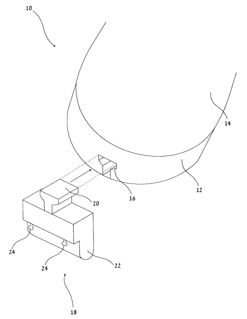
Referring now to the drawings, Figures 1-4 show a first embodiment of a
therapeutic shoe, generally designated 10, configured to facilitate shifting
the
weight exerted on the foot of a wearer (not shown) as required. Generally
speaking, shoe 10 includes a sole 12 providing an upper surface for supporting
the foot of the wearer, and an upper portion 14 associated with sole 12 and
configured to retain the foot of the wearer in contact with the sole. A
recessed
track 16 is formed in the lower surface of sole 12 and extends substantially
parallel to a dimension of the sole termed "length" along a major portion of
the
length. A support block 18 has an engagement projection 20 configured for
engaging recessed track 16 and a load-supporting body 22 configured to extend
in a direction substantially perpendicular to the length. Support block 18 is
configured so as to be attachable to the lower surface of sole 12 at any one
of a
plurality of positions along substantially the entirety of recessed track 16.
It will be readily apparent that therapeutic shoe 10, formed from
standard components suitable for mass production techniques, readily allows
positioning of one or more support block 18 to offer personalized weight
shifting and pressure release. Furthermore, support block 18 may subsequently
be adjusted and, after the completion of the therapy, may be removed
altogether
to allow shoe 10 to be used as a normal shoe.
Turning now to the features of therapeutic shoe 10 in more detail,
recessed track 16 is preferably open at at least one end of sole 12 and, most
preferably, extends the full length of sole 12 so as to be open at both ends
(see
Figure 3A). Optionally, in the case that both ends are open, track 16 may be
interrupted at some point along its length, such as to provide a region of
reinforcement for sole 12. Track 16 preferably includes at least one undercut
ridge, most preferably in the form of a substantially T-shaped track, as
shown.
Engagement projection 20 is preferably configured to engage the
undercut ridge of track 16. In the case of a T-shaped slot, engagement
projection 20 is preferably formed with a complementary T-shaped cross
section. This serves to retain support block 18 against sole 12, and to define
6
CA 02391513 2002-05-23
WO 01/37693 PCT/IL00/00780
both the lateral position and the orientation of support block 18 relative to
sole
12 There remains only one degree of freedom for adjustment of the support
block, namely, in the frontward-rearward directions relative to sole 12.
The required position of each support block 18 along track 16 is
preferably fixed by tightening of one or more fastening element which extend
through block 18 into sole 12. Preferably, these are implemented as at least
two
threaded fastening elements 24, typically in the form of self drilling screws,
which are inserted through a fastening flange of the support block (see Figure
2) and are configured to become lodged in sole 12 when tightened.
Alternatively, the engagement projection is preferably made up of a
number of parts, as illustrated in Figures 3A and 3B. In Figures 3A and 3B, a
three-pieced embodiment of support block 18 is shown, where load-supporting
body 22 is permanently associated with engagement ridge 24 and where
attachment plate 26 can be operationally connected to it in some way, such as
by using screw 28. Tightening screw 28 into threads in attachment plate 26
while engagement ridge 24 is engaged in track 16 reduces the gap between
attachment plate 26 and load-supporting body 22, squeezes the edges of
undercut track 16 and so retains support block 18 in place against sole 12.
Engagement ridge 24 defines both the lateral position and the orientation of
support block 18 relative to sole 12. The pressure exerted by attachment plate
26 and load supporting body 22 by the action of screw 28 produces sufficient
frictional force that support block 18 remains substantially immobile relative
to
sole 12.
The position of support block I8 along track 16 is preferably adjusted by
releasing screw 28 so as to reduce the pressure exerted on the sole by
engagement projection 20, allowing support block 18 to slide along the
recessed track while engagement projection remains substantially engaged in
track 16. Re-tightening screw 28 fixes support block 18 in the desired place
along the length of sole 12,
7
CA 02391513 2002-05-23
WO 01/37693 PCT/IL00/00780
Load-supporting body 22 typically has a height (i.e., the extent to which
sole is raised locally above the underlying surface) of up to about 2 cm.
Depending upon the intended therapy, heights of either about 2 cm or about 1
cm are thought to be preferred. In order to make walking as comfortable as
possible, load-supporting body ZZ preferably has a rounded lower profile as
viewed along its direction of extension, i.e., from the side as seen in
Figures
4A-4D. Furthermore, load-supporting body 22 typically extends across at least
half the width of the sole of the shoe to maximize stability and comfort when
walking and to evenly distribute pressure along the width of the foot of the
wearer.
Turning now to Figures 4A-4D, these show four typical examples of
configurations formed using therapeutic shoe 10 for pressure relief therapy.
Referring first to Figure 4A, this shows a configuration employing a single
support block 18 located in a forward position, shifting weight to the rear of
the
foot and offering forefoot protection. Figure 4B shows a second configuration,
shifting the weight to the front of the foot thus providing heel protection.
Figures 4C and 4D show further configurations in which two similar
support blocks 18 are attached at different positions along track 16. In the
configuration of Figure 4C, the two supports are located at extreme positions
to
shift the weight to the front and back of the foot thus providing mid-foot
protection. In Figure 4D, they are brought inwards to shift the weight towards
the center of the foot and thus to offer simultaneous forefoot and heel
protection.
Figures SA-SC, illustrate typical examples of configurations of
therapeutic shoe 10 useful for wearers suffering from LLD.
Referring first to Figure SA, this shows a configuration employing a
single support block 18 located in the heel position, raising that part of the
shoe
so as to allow comfortable walking. In Figure SA, two screws are shown used
to fix support block 18 in place.
8
CA 02391513 2002-05-23
WO 01/37693 PCT/IL00/00780
Figures SB and SC shows a different configuration, where two support
blocks 18 are used to raise sole 12 to be substantially parallel to the ground
when the wearer is standing. Both the number of support blocks and the heights
of each support block are decided upon, for example, by a physician. In Figure
SC an additional embodiment of attachment plate a substantially L-shape 28 is
shown. The L-shape allows simple adjustment of the location of support block
18 at the heel of the shoe.
As can be seen in Figure SA, when the invention is used to help wearers
suffering from LLD, it is possible that support block 22 be somewhat wider to
make more contact along the length of sole 12 so as to minimize the pressure
distribution aspect of the invention. It is also possible to see in Figures SA
and
SB that, in order to compensate for the leg length discrepancy, load-
supporting
body 22 may raise sole 12 higher than in the case of pressure relief.
Sole 12 and load-supporting body 22 are each made from any suitable
material. Typically, both are made from polymer materials of types
conventionally used for shoe soles as are known in the art. Such materials
inherently provide an appropriate degree of flexibility to distribute the
weight
of the wearer in a gradual manner over the region of sole 12 proximate to load-
supporting body 22.
Similarly, upper portion 14 is made from any suitable material.
Typically, it is formed from either leather or synthetic materials commonly
used for shoe uppers. It should be noted that the type and style defined by
the
shape of upper portion 14 is not salient to the invention. Thus, in the
particular
preferred example illustrated here, upper portion 14 is formed with an open
toe,
thereby forming a sandal configuration. However, a closed-toe shoe is
preferred
for some applications.
Turning now to Figures 6 and 7, as mentioned above, the present
invention provides a second set of features which are used alone or, as shown,
together with the features described above to avoid pressure on the heel of a
foot supine wearer. Thus, a therapeutic shoe is shown, generally designated
30,
9
CA 02391513 2002-05-23
WO 01/37693 PCT/IL00/00780
constructed and operative according to the teachings of the present invention.
Generally speaking, therapeutic shoe 30 has a sole 32 providing an upper
surface for supporting the foot of the wearer, and having a rear edge 34. In
this
case, an upper portion 36, associated with sole 32, is configured to retain
the
foot of the wearer in contact with sole 32 in a position such that the heel of
the
foot lies adjacent to rear edge 34. Upper portion 36 has at least one opening
38
adjacent to rear edge 34 configured to avoid contact with at least a part of
the
heel of the foot. A pressure release bracket 40 is configured to releasably
engage sole 32 so that the sole is supported by pressure release bracket 40
with
its rear edge 34 raised above the underlying surface.
It will be appreciated that the structure described ensures that the heel of
the wearer does not experience any contact pressure with the adjacent
surfaces.
Specifically, over a wide range of "heel-down" foot positions, the weight of
the
foot is always transmitted through sole 32 to upper portion 36 which is
configured to retain the foot without exerting any pressure on the heel. When
the wearer has finished resting and the heel protection function is not
currently
required, bracket 40 is readily removed, as shown in Figure 7, to allow shoe
30
to be used for walking.
It will be appreciated that a wide range of structures can provide the
function of pressure release bracket 40. In one particularly simple and
preferred
implementation illustrated in Figure 6, pressure release bracket 40 is
implemented as a substantially flat sheet of metallic or polymer material. In
this
case, sole 32 preferably features a slot 42 adjacent to rear edge 34 within
which
pressure release bracket 40 is configured to sedge or clip into place.
Another preferred implementation for pressure release bracket is
illustrated in Figures 8 and 9. In this implementation, one part of pressure
release bracket 40 engages slot 42 adjacent to the rear edge of the sole and
the
other part is reversibly connected to the upper part of the shoe or fixed
around
the leg of the wearer with straps 46. The shape and rigidity of pressure
release
bracket 40 is such that when used in conjunction with straps 46 pressure on
the
CA 02391513 2002-05-23
WO 01/37693 PCT/IL00/00780
heel of the foot of a supine wearer is relieved, the heel is protected from
painful
or damaging incidental contact, and the weight of the foot is redistributed
through straps 46 to the ankle and leg of the wearer. Straps 46 can be made
from any suitable material, such as leather or woven material, and be
tightened
around the leg or ankle of the wearer using suitable means such as buckles or
Velcro~.
As mentioned earlier, these features may optionally be used in
combination with the above mentioned weight-shifting therapy features.
Accordingly, the preferred embodiment shown here additionally features the
track 16 and support block 18 described above.
It will be appreciated that the above descriptions are intended only to
serve as examples, and that many other embodiments are possible within the
spirit and the scope of the present invention.
11