Note: Descriptions are shown in the official language in which they were submitted.
CA 02391543 2002-06-25
-1-
APPARATUS AND METHOD FOR REMOVING CONCRETE FROM
INTERIOR SURFACES OF A CONCRETE MIXING DRUM
Technical Field
The present invention relates generally to
apparatus for removing residual concrete from the
interior of a concrete mixing drum, and more
particularly to apparatus including an elongate
probe supported for axial movement into and out of
an open end of the drum, preferably automatically,
and including at Least one nozzle positioned for
discharging fluid under pressure against difficult
to access interior surfaces of the drum,
particularly surfaces on helical ribs or flights
facing away from the open end of the drum, on which
surfaces concrete tends to cure and accumulate, for
dislodging and removing the concrete.
Background Art
Ready-mix concrete trucks have a rotatable
drum for holding a quantity of ready-mix concrete.
The drum typically includes several raised helical
ribs or flights extending around its interior
surfaces. These ribs act to mix the concrete when
the drum is rotated in one direction, and when the
drum is rotated in the opposite direction, the ribs
lift the concrete to an elevated opening, either at
the front or rear of the drum, through which the
concrete is discharged from the drum. Over the
course of operation, concrete has been found to
accumulate on the surfaces in the drum, particularly
on the rib surfaces facing away from the open end of
the drum: This concrete, if left in place to cure
and harden, has been found to decrease the
effectiveness of the ribs for both mixing and
lifting the concrete,'and adds weight to the truck.
The concrete, if allowed to accumulate, will alsa
CA 02391543 2002-06-25
-2-
lessen the capacity of the drum. Therefore, it is
common practice, at the end of each day, or more
often, to wash the interior of the drum. However,
the washing typically requires as much a5 300
gallons of water, and still has been found to be
ineffective at removing the accumulated concrete
from the surfaces of the ribs facing opposite the
open end of the drum, especially if the concrete is
allowed to cure and harden.
Reference Steinke U.S Patent No. 5,244,498
issued September l4, 1993 to W.R. Grace and Co. of
Canada Limited; and Hailey U,S Patent No. 5,507,875
issued April 16, 1996, which disclose various known
apparatus and methods for cleaning concrete mixing
drums. More particularly, Steinke teaches manual
insertion of a hand held elongate probe into a
concrete mixing drum for spraying a set retarding
agent against the residual concrete on the inner
surface of the drum for removing the concrete.
Hailey discloses utilizing a vibration impact device
applied against the exterior of the concrete mixing
drum for loosening and di lodging the accumulated
concrete.
Shortcomings of relying on a retarding
agent such as disclbsed in Steinke for ridding a
concrete mixing drum of residual concrete include
observed ineffectiveness of the retarding agents
under a variety of environmental conditions such as
elevated temperatures. Additionally, the retarding
agents have been found to be generally ineffective
for removing concrete that has largely or mostly
cured. Limitations of using hand held devices like
the Steinke probe include unwieldiness when fully
extended into a drum,~particularly when using
pressurized fluids. Also, it is unsafe to rotate
the drum when any hand held device is used therein.
Shortcomings of vibrational methods of cleaning
CA 02391543 2002-06-25
-3-
concrete mixing drums such as disclosed in Hailey
include the noise generated by the vibrating devices
and the time required: Further, it has been found
that the known cleaning apparatus and methods often
still leave sufficient residual concrete on the
interior surfaces of the drum so as to require
periodic manual cleaning.
Manual cleaning typically involves a
worker entering the drum, and, using a water hose
and hand tools as required, loosening the concrete
from the drum surfaces and washing the concrete
pieces to the bottom of the drum. Then, the worker
exits the drum, and the drum is rotated so as to
discharge the cleaning water and concrete pieces
from the drum. Shortcomings here include the
possibility of the worker being injured while
entering or exiting the drum, which requires a
ladder or similar means, or from slipping or falling
' on the wet surfaces in the drum. The worker can
2o also be injured by loosened pieces of concrete which
can fall from the upper surfaces in the drum. Also,
it is noisy in the drum during the cleaning
operation as a jackhammer, sledge hammer or similar
device is typically used to beat the concrete off of
the interior surfaces.
Accordingly, the present invention is
directed to overcoming one or more of the
shortcomings as discussed above.
Disclosure of the Invention
In one embodiment of the present
invention, an apparatus for removing concrete from
the interior surfaces of a concrete mixing drum is
disclosed, the drum including an open end and at
least one interior surface facing away from or
opposite the open end, the apparatus comprising an
elongate probe having a longitudinal axis and an
CA 02391543 2002-06-25
-4-
axially extending forward end adapted for insertion
into the drum through the open end thereof; a
vertically adjustable support structure supporting a
guideway support, the guideway support including at
least one bearing adapted for supporting the probe
for movement of the forward end thereof into and out
of the drum through the open end thereof; and at
least one fluid nozzle mounted to the probe in
position for discharging a stream of fluid agains t
the at least one interior surface facing opposite
the open end under sufficient pressure to dislodge
accumulated concrete therefrom as the probe is moved
in the drum.
In a preferred method of operation, the
I5 elongate probe of the apparatus is positioned for
insertion of the forward end thereof into the open
end of the drum. The probe can then be axially
moved into the drum and the fluid under pressure
delivered through the fluid conduit to the nozzle
for discharging the stream of fluid under pressure
against the interior drum surface for dislodging the
concrete. During this dime; the drum is rotated in
the discharge direction and the probe is moved
axially into or out of the drum such that the
interior surfaces thereof, most importantly the
surfaces of the helical ribs or flights facing away
from the open end of the drum, are reached by the
stream of fluid. Then, once the probe has traversed
essentially the length of the drum, the probe is
withdrawn from the drum, and the concrete removal
operation is complete when the dislodged material is
discharged from the drum.
In a preferred aspect of the invention, at
least four fluid nozzles are provided at different
positions adjacent the end of the probe for
discharging the streams of fluid under pressure in
different directions, the preferred fluid stream
CA 02391543 2002-06-25
-5-
being a pencil shaped stream, although solid cone
shaped streams, hollow cone shaped streams, and fan
shaped streams, can likewise be used.
Here, is should be recognized that the
fluid stream can comprise any material effective for
dislodging accumulated concrete from the drum
surfaces, including, but not limited to, liquids
such as water either alone or including a detergent,
gritty matter or the like which can be introduced
into the fluid stream after discharge from the
nozzle; and cryogenic materials such as pelletized
dry ice, and the like.
Brief Description of.Drawinas
Fig. 1 is a schematic representation of
apparatus for removing concrete from the interior
surfaces of a concrete mixing drum according to the
present invention shown in operative position for
use in a concrete mixing drum of a ready-mix
delivery truck;
Fig. 2 is a top view of an elongate probe
of the apparatus of Fig. 1;
Fig. 3 is a fragmentary side view of
support structure of the apparatus of Fig. 1;
Fig. 4 is a end view of the apparatus of
Fig: 1;
Fig. 5 is a bottom view of the apparatus
of Fig. l showing a motor and drive assembly for
moving the probe thereof longitudinally into and out
of the concrete mixing drum; and
Fig. 6 is a side view of the apparatus of
Fig. 1, shown mounted in the bed of a truck for
mobile operation.
Best Mode for Carrying Out the Tnvention
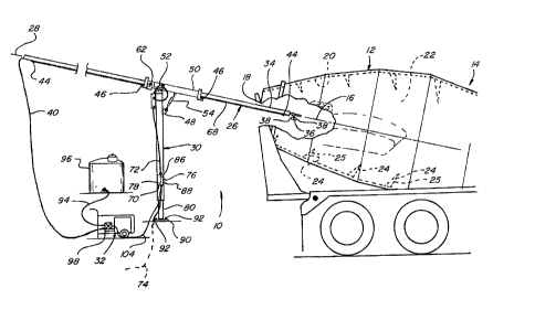
Referring to the drawings, Fig. 1 shows
apparatus 10 constructed and operable according to
CA 02391543 2002-06-25
_g.
the teachings of the present invention for removing
concrete from the interior of a concrete mixing
drum. Apparatus l0 is shown in operative position
for cleaning the interior of a conventional
rotatable concrete mixing drum 12 of a ready mix
delivery truck 14. Truck 14 is representative of a
wide variety of trucks for mixing and delivering
concrete to job sites, and generally includes means
operable for rotating drum 12 in a c7.ockwise
direction, and also a counter clockwise direction,
about a drum axis 16, as desired. Drum 12 includes
an open end 18, and an interior surface 20 defining
an interior cavity 22. A plurality of helical ribs
24 extend around interior surface 20 and are
operable when the drum is rotated in one direction
to mix concrete located in interior cavity 22, and
lift the concrete for discharge through open end 18
when the drum is rotated in the opposite direction.
Helical ribs 24 each have a surface 25 extending
around cavity 22; which surfaces 25 face away from
open end 18 and are often orientated at an acute
angle to surface 20. Here, it should be noted and
understood that drum 12 is contemplated to be
representative of a wide variety of commercially
available drums of different sizes, shapes, and
number and arrangement of helical ribs 24 or
flights, apparatus l0 having utility for removing
concrete from the interior surfaces of all such
drums.
Apparatus 10 includes an elongate probe
26. Probe 26 is supported for longitudinal movement
along a longitudinal axis 28 thereof by a vertically
adjustable support structure 30. Apparatus 10
further includes a powered pump for delivering fluid
under pressure to probe 26. Elongate probe 26 is
preferably from about 20 to about 3O feet long, the
length thereof depending on the length of the drum
CA 02391543 2002-06-25
being cleaned; a length of 28 feet having been found
to be adequate for most applications tested. Probe
26 includes an axially. extending forward end portion
34 adapted for insertion into a drum, such as drum
5, 12, through the open end thereof. Forward end
portion 34 includes a nozzle manifold 36 mounted
adjacent the forward end thereof, nozzle manifold 36
having a plurality of nozzles 38 mounted thereto.
Referring also to Fig. 2, nozzles 38 are
arranged in an angularly spaced, horizontal array
such that each nozzle is pointed in a different
direction. Each nozzle is adapted for discharging a
stream of fluid under pressure against the roterior
surface 20 of drum 12. The preferred stream is a
narrow or pencil shaped stream, other streams such
as solid cones, hollow cones and fan shaped streams
also being usable. Each nozzle preferably has an
oppositely facing court erpart such that the forces
generated by the oppositely directed streams
discharging therefrom largely cancel each other or
balance out. A high pressure hose 40 is connected
between nozzle manifold 36 and pump 32, providing a
fluid conduit for the flow of fluid under pressure
from pump 32 to manifold 36, the pressurized fluid
being distributed through manifold 36 to respective
nozzles 38 for discharge therethrough. Hose 40
preferably extends through probe 26 (Fig. 4) but
could alternatively be mounted externally thereto,
as desired. Other preferred features of probe 26
include an optional conventionally constructed and
operable stop switch 42 for stopping the powered
longitudinal advance of probe 26 when the end of
drum 12 opposite open end 18 or other obstacles are
contacted.
Referring to Fig. 3, magnets 44 are
located at predetermined locations on probe 26 for
activating proximity switches 46 located adjacent
CA 02391543 2002-06-25
_8_
the respective opposite ends of support structure 30
and operable in the conventional manner for limiting
the longitudinal travel of probe 26, as will be
explained. Support structure 30 includes an
upstanding column 48 of tubular or similar
construction and a guideway support 50 pivotally
mounted cross-wise atpivot 52 to column 48 for
pivotal movement in a generally vertical plane
relative to the column. An adjustable turnbuckle 54
extends between column 48 and guideway support 50.
Turnbuckle 54 is a manually adjustable device of
conventional construction and adjustment thereof by
relative rotation of a threaded nut 56 and a
threaded rod 58 enables positioning probe 26 at a
suitable angular orientation for insertion into a
drum such as drum 12 through the open end thereof.
Here, it should be noted that it has been found that
an angle of between about 11°and about 13° to
horizontal is suitable to allow insertion of probe
26 into the drums of a wide variety of ready mix
trucks. It should also be noted that it is not
critical that the probe angle match the angle of the
drum axis, with the additional cautionary note that
probe 26 should be capable of being extended into
and withdrawn from a drum without contacting the
drum.
Referring also to Fig. 4, guideway support
50 is preferably a tubular member or truss of at
least 4 feet in length and having an interior cavity
adapted for receiving probe 26. Probe 26 is
supported within and by guideway support 50 for
longitudinal movement along axis 2'8 by a plurality
of bearings 60 located at upper and lower positions
adjacent the ends of guideway support 50.
Referring also to Fig. 5, a motor and
drive assembly 62 operable for moving probe 26
axially is shown. Motor and drive assembly 62
CA 02391543 2002-06-25
-g-
includes an electric motor 64 mounted on guideway
support 50 and connected in driving relation to a
pinion 66 enmeshed with a rack 68 extending
longitudinally along a substantial portion of probe
26. Rack 68 is preferably made from a polymeric
material such as nylon due to its light weight, and
its resistance to attack by alkali, non-reactivity
electrically with magnesium, and low frictional
properties. Referring in particular to Fig. 3,
motor 64 is electrically connected by wires
contained in a conduit 72 to a controller 70 mounted
to column 48. Electrical power is provided to
controller 70 from a power source (not shown) by
power cord 74. Controller 70 further includes an
operator controllable on/off switch 76 and a
directional control switch 78 operator operable for
moving probe 2G longitudinally into and out of a
mixing drum. Stop switch 42 and proximity switch 46
are operable in conjunction with controller 70 to
limit the extent of movement of probe 26 such that
the probe and nozzles 38:wi11 not be damaged by
contact with the end of a drum, and such that the
probe will not travel so far in either direction
such that rack 68 and pinion 66 are disengaged.
Column 48 includes two sections, a lower
section 80 and an upper section 82, lower section 80
preferably being constructed of 5" X 5" square steel
tubing, and upper section 82 being constructed of 6
X 6" square steel tubing mounted in telescoping
relation over lower section 80. Upper section 82
slides over lower section 80 on bearings of a
polymeric material having self-lubricating
properties such as Delrin brand thermoplastic
available from DuPont, or other suitable lubricating
material. A second motor and drive assembly 84
mounted on upper section 82 is drivingly connected
to a threaded rod mounted inside column 48 and
CA 02391543 2002-06-25
-10-
supporting upper section 82 via a conventional fixed
nut and bearing to raise or lower the upper section
82 relative to lower section 80 as desired. Motor
and drive assembly 84 is electrically connected to
controller 70 by wires contained in conduit 72 and
is controlled by a second on/off switch 86 and a
second directional control switch 88. Motor and
drive assembly 84 is operable using switches 86 and
88 to raise and lower upper section 82, guideway
support 50 and probe 26, through a range of from
about 3 to about 4 feet to enable adjusting the
height of probe 26 for use with different trucks. A
horizontal base plate 9O welded to lower section 80
is attachable to a concrete pad, foundation or other
member with bolts 92 in the conventional manner.
The preferred pump 32 is a high pressure
pump operable to pressurize fluid discharged through
nozzles 38 at at least about 300 psi, and as high as
about 8000 psi, and most preferably within a range
of from about 1000 to about 4000 psi, at a flow rate
of from about 4 to about 12 gallons per minute.
Pump 32 may be powered by electricity, fossil fuel
or any other means, a commercially available
gasoline powered high pressure pump being shown.
The preferred fluid used for cleaning is water, free
of particulate matter, received through hose 94 from
a water source; such as tank 96. Recycled water is
usable, as long as the water is adequately treated
to remove sand and cement particles: Flow of fluid
under pressure from pump 32 to nozzles 38 is
controlled by a solenoid valve 98 operable using a
switch 100 on controller 70 connected to the
solenoid valve via wires 102. Switch 100 is
operable to open valve 98 to allow fluid flow to
nozzles 38 when located in a drum such as the drum
12, and to close valve 98 to allow recirculation of
the fluid through pump 32. Solenoid valve 98 is
CA 02391543 2002-06-25
-11-
also preferably controllable by proximity switches
46 on guideway support 50 such that when a
predetermined magnet 44 on probe 26 is sensed, valve
98 is opened to commence the cleaning operation.
Then, as probe 26 is withdrawn from the drum such
that a magnet 44 closer to forward end portion 34 is
Sensed by proximity switch 46, valve 98 is closed.
Here, it should be recognized and understood that
more than one magnet 44 and proximity switch 46 can
be used at each opposite end of guideway 50, the
magnets 44 being located a different locations
corresponding to the lengths of different drums; and
the proximity switches 46 for sensing the different
magnets being selectively activated for selecting a
drum length. Still further, solenoid valve 98 can
optionally be controlled by directional control
switch 78 to close when probe 26 is moved in one
direction or the other.
Operation of apparatus l0 can be performed
in various ways. One preferred method of operation
is to position a ready-mi,x delivery truck such as
truck 14 a suitable distance away from forward end
portion 34 of probe 26, with drum axis 16 and axis
28 of the probe in the desired relation. Switches
86 and 88 can then be operated, as required, to
position probe 26 at the proper height for the drum
to be cleaned. If necessary, turnbuckle 54 can be
adjusted to achieve the desired angular relationship
between drum axis 16 and axis 28 of the probe.
Motor 64 is then energized using switches 76 and 78
to drive probe 26 through open end 18 of the drum
and into the interior thereof. Here, the travel of
probe can be operator controlled using visual
indicia such as marks 104 (Fig. 3) on the probe
corresponding to different truck lengths, or the
travel can be controlled by one or more of the
proximity switches 46, or stop switch 42, to fully
CA 02391543 2002-06-25
-12-
extend probe 26. With probe 26 fully extended in
the drum, the drum is rotated in the direction for
discharging the contents thereof. Solenoid valve 98
is then opened, either by moving switch 78 to the
retract mode or using a separate switch, and probe
26 is moved slowly out of the drum while the fluid
discharged from nozzles 38 impinges any residual
concrete on the interior surfaces of the drum
thereby loosening or dislodging the residual
concrete. Here, it should be noted that it is
important that at least one of nozzles 38 is pointed
in a rearward direction preferably at an acute angle
relative to axis 28 of probe 26 such that
accumulated concrete on surfaces 25 of ribs 24
opposite open end 18 is reached by the fluid streams
and dislodged. The horizontal orientation of the
nozzle array, or a more upwardly directed discharge
pattern has been found to facilitate cleaning such
that the fluid does not impinge collected water in
the bottom of the drum, and is safer because the
high pressure streams are,not pointed downwardly so
as to possibly injure a person standing by the probe
in the event of accidental operation with the
nozzles located outside of a drum. When the drum is
fully cleaned, fluid flow is then turned off either
manually, or when one of the proximity switches 46
is activated, and probe 26 is moved until fully
withdrawn from the drum. As an alternative method,
the flow can be directed through nozzles 38 as probe
26 is moved into the drum, or both during insertion
into and withdrawal from the drum.
Here, it should also be noted and
understood that it is contemplated that alternative
structures and drive mechanisms for apparatus 10
could be used. For instance, probe 26 could be a
telescoping structure operably extended and
retracted using a threaded rod and fixed nut or
CA 02391543 2002-06-25
-13-
other suitable mechanism. Similarly, a rack and
pinion or other mechanical drive can be utilized
instead of the threaded rod and nut mechanism
discussed above for raising and lowering probe 26.
Also, a powered mechanism could be provided in
cooperation with or in lieu of turnbuckle 54 for
varying the angle of probe 26. Further, a constant
discharge stream from nozzles 38 could be used, or a
pulsating stream, as desired. Other support
structures can likewise be used; such as a gantry
wherein the probe is suspended.
Referring to Fig. 6; apparatus 10 is shown
mounted atop the bed of a truck 106 for mobile
operation. Support s ructure 30 is shown mounted to
the truck, with probe 26 movable into and out of a
drum, such as the drum l2, using controls such as
controller 70 located inside, or, outside of the
operating cab of the truck. Pump 32 and tank 96 are
also mounted on the truck, hose 40 connecting pump
32 with nozzle manifold 36 as explained above.