Note: Descriptions are shown in the official language in which they were submitted.
CA 02391554 2002-05-15
WO 01/36123 PCT/SE00/02235
TITLE: TOOL ASSEMBLY
TECHNICAL FIELD
The present invention relates generally to tool assemblies and in particular
relates to improve-
menu in methods and devices for closing tool assemblies and for maintaining
them closed
during tool operation.
BACKGROUND
Hydroforming is a well known process for forming metal workpieces by means of
pressurized
fluid. It is performed using high fluid pressures that are applied internally -
such as by internal
hydroforming of tubes or pipes - or externally - such as by hydromechanical
forming or flex-
forming of sheet metal - to workpieces that are mostly relatively thin-walled
and that are
positioned in a tool. In the internal hydroforming the conventional tools
consist of upper and
lower tool halves and/or tool holder halves that are vertically movable
relative to each other.
L 5 The tool halves carry upper and/or lower dies respectively, and are
relatively movable bet-
ween an open position for loading blanks and for unloading processed
workpieces, and a
closed position in which the fluid pressure is applied to the blank. Generally
speaking the
blank is formed by forcing it into contact with the wall or walls of a hollow
space or cavity
formed by the die or dies between the tool halves. In the flexforming process
the upper tool
'_ 0 half/tool holder is replaced by a plate holder which through a flexible
membrane closes the die
cavity formed in the lower tool and which forms a pressure fluid space above
the membrane
and the blank. However, in this specification this type of plate holder for
the flexforming
process will likewise be generally referred to as an upper tool half.
5 The very high fluid pressures applied to the workpiece for the forming
operation generate
extreme outwardly directed forces acting to push the dies and thereby the
tools apart. The
fluid pressure applied to the workpiece, and thus also to the tool halves,
from within the
hollow space formed by the dies, is often in the order of several thousand
bars. The resulting
tool separating forces are likewise extremely high, and will for most
applications amount to
0 several thousand kN. Obviously it is vital for the hydroforming process that
the tool halves
and specifically the dies are securely closed and maintained in their mutual
position during the
entire forming process. In the conventional apparatus for performing
hydroforming a powerful
CA 02391554 2002-05-15
WO 01/36123 PCT/SE00/02235
2
press provides the extreme closing forces. Normally the press ram carries the
upper tool half
and the lower tool half is stationary and supported on a machine base.
The conventionally employed press may be required to produce a closing force
of up to about
100 000 kN and is in any event, even for hydroforming processes for smaller
workpieces,
extremely expensive and requires a great amount of space. Naturally, the very
high cost of the
press and the complexity of the hydrofonning apparatus, as such, make the
total investment
cost unbearable to many small and middle size companies, and thereby limits
the availability
of the hydroforming processes. In practice the conventional technique will
therefore only be
available to larger companies. The hydroforming techniques have exceptional
advantages over
many traditional forming techniques, and therefore there is a general need
within this field for
improvements that may reduce the complexity and cost of the equipment for
hydroforming
and that may simplify the process.
Although the above discussed problems and circumstances are emphasized within
the field of
hydroforming they do indeed also exist within other technical fields, such as
injection
molding. Therefore the need for improved technical solutions eliminating tool
closing and
holding problems is not restricted to said hydroforming field, but applies to
any molding or
forming technique working with raised internal pressures.
RELATED ART
U.S. Patent no. 5 927 120 discloses an apparatus for performing hydroforming
of the general
kind described above. The apparatus comprises upper and lower pressure
vessels, each
carrying a tool holder for receiving a corresponding tool or die section. The
apparatus is
2 5 provided with mechanical locking means for locking the upper and lower
pressure vessels to
each other during the forming process. Said locking means consist of locking
pins that may be
inserted into and retracted from complementary holes in the pressure vessels,
performing a
pure latching function in their inserted position. According to the patent the
apparatus is
deliberately designed so as to allow outward deflection of the pressure
vessels under the
3 0 influence of the force from the fluid pressure applied to the workpiece.
In other words no
closing force is applied to the pressure vessels. Instead, the die sections
are forced into
CA 02391554 2002-05-15
WO 01/36123 PCT/SE00/02235
3
engagement with each other by pressurizing an inflatable bladder positioned
underneath the
lower die section.
SUMMARY
The invention overcomes the above problems in an efficient and satisfactory
manner.
A general object of the invention is to provide a solution to the problem of
securely and
accurately holding together the tool halves of a forming tool that during the
forming process
experiences a very high internal pressure.
LO
In particular, it is an object of the invention to provide an improved tool
assembly presenting
an uncomplicated and inexpensive solution to the above discussed problems.
Briefly, this is
achieved by means of a tool assembly in which a tool closing force is applied
to a forming
tool by means of at least two closing force actuators. In a tool closing
position said closing
_ .5 force actuators apply a closing force to a lower tool section and an
upper tool section through
a pair of tool clamps. The tool clamps and the respective tool sections engage
each other with
inclined contact surfaces. The actuators apply the tool closing force during a
forming process,
whereby the clamps take up a portion of a tool separating force generated by
internal forming
pressure in the tool. The elasticity of the clamp material results in a
certain widening of the
'.0 clamp under the influence of the tool separating force, and this clamp
widening is
compensated for by the continuous readjustment of the clamp through the
application of the
closing force. Only a reduced portion of the full tool separating force has to
be counteracted
by the closing force actuators, the size of which will therefore be reduced.
'. 5 In an embodiment of the invention the actuators are linear actuators
applying the closing force
in a direction substantially parallel to a parting plane of the forming tool.
This provides for an
effective and yet simple and inexpensive design.
In a further practical embodiment the actuators are hydraulic cylinders being
connected to at
0 least one tool clamp of a pair by means of their piston rods. By connecting
the hydraulic
cylinders to a variable pressure fluid source it is furthermore possible to
van' the applied
closing force in dependence upon actual forming pressures.
CA 02391554 2002-05-15
WO 01/36123 PCT/SE00/02235
4
In further embodiments the tool clamps are made up of a base portion and jaws
extended
outwardly from said base portion, the actuators applying their closing force
to the jaws,
preferably to outer areas thereof. With such embodiments it is possible to
positively
counteract the tendency of the clamps being widened by tool separating forces.
In order to reduce friction between inclined contact surfaces of the tool and
the clamps, and thus
the wear of said surfaces, it is suggested to provide steel plates in the
contact surfaces of the tool
and to provide plates of a synthetic material in the contact surfaces of the
clamps.
In further embodiments of the invention the contact surfaces are all inclined
with the same
angle that is preferably smaller than 45°, so that the clamp material
takes up the major portion
of the separating force, whereas only a smaller portion thereof has to be
counteracted by the
closing force actuators, so that the size thereof may be substantially
reduced. In the most
preferred embodiments said angle is between 6° and 12°,
preferably 10°.
Preferred further embodiments of the tool assembly of the invention are
specified in the
respective dependent claims.
2 0 Another object of the invention is to provide an improved and very
effective closing force
application unit for a forming tool, presenting a solution to the problem of
providing a closing
force that securely and reliably counteracts the tool separating forces. In
accordance with the
invention this object is achieved by means of a closing force application unit
consisting of at
least one pair of tool clamps and at least two closing force actuators
connected to each pair of
2 5 clamps, said actuators applying a closing force to the tool during a
forming process therein,
through the clamps and through inclined contact surfaces on the clamps and on
the tool.
Preferred embodiments of the closing force application unit of the invention
are specified in
the respective dependent claims.
Yet another object of the invention is to provide a method of closing upper
and lower tool
sections of a forming tool. In order to counteract the force generated by the
forming pressure
CA 02391554 2002-05-15
WO 01/36123 PCT/SE00/02235
and to maintain the tool sections in firm contact with each other, a closing
force is applied to
the tool. According to the invention the closing force is basically applied in
a direction parallel
to the parting plane of the tool sections. The closing force is applied to the
tool through in-
clined contact areas on upper and lower, outer surfaces of the tool sections
on the one hand,
5 and on inner facing surfaces of closing force application units on the other
hand. This
essentially reduces the closing force requirement, since the material of the
force application
units takes up part of the separating forces produced by the forming pressure.
In an embodiment of the method the closing force is controlled in dependence
upon the actual
_ 0 generated tool separating force.
These and further objects of the invention are met by the invention as defined
in the appended
patent claims.
_ 5 In summary, the present invention provides the following advantages over
the state of the art:
The force required for counteracting the internal pressure from the forming
operation
within the tool, i.e. the force required for closing the tool during the
forming cycle, is
significantly reduced.
'.0
It provides a secure and precise locking or holding together of the tool
sections even in
applications with extreme internal pressures.
As a result of the reduced closing force requirement the size, complexity and
cost of the
'. 5 closing force actuators can be greatly reduced.
It will be possible to eliminate any tendency of the tool clamps being widened
by the tool
separating forces.
0 . The cycle times are substantially reduced as a result of the reduced
closing force require-
ment and the concomitant reduced actuator size.
The tool will be easily accessible for positioning of blanks in the die and
for removal of
finished workpieces from the die, as well as for die changing and service
work.
5
CA 02391554 2002-05-15
WO 01/36123 PCT/SE00/02235
6
Other advantages offered by the present invention will be readily appreciated
upon reading the
below detailed description of embodiments of the invention.
BRIEF DESCRIPTION OF THE DRAWINGS
The invention, together with further objects and advantages thereof, may best
be understood by
making reference to the following description taken together with the
accompanying drawings,
in which:
Fig. 1A is a partial side view schematically illustrating a first embodiment
of the tool
assembly of the invention applied to a hydroforming apparatus, with closing
force actuators in an extended position, engaging the forming tool;
Fig. 1 B is a partial side view of the first embodiment of the tool assembly,
with the
closing force actuators in a retracted position;
L5
Fig. 1 C is a partial plan view from above of the embodiment illustrated in
figs. 1 A and
1B;
Fig. 2 is a perspective view of a practical configuration of a closing force
application
? 0 unit in accordance with the first embodiment of the invention illustrated
in figs.
1 A-C;
Fig. 3 is an enlarged cross-section, taken along line A-A in fig. 1 C, through
a closed
hydroforming tool of the embodiment illustrated in figs. 1 A-C;
?5
Fig. 4 is an enlarged cross section taken along line A-A in fig. 1 C, through
an opened
hydroforming tool of the embodiment illustrated in figs. lA-C;
Fig. 5A illustrates an enlarged and partially sectioned detail of an
alternative embodi-
0 ment of a tool and an associated tool clamp of a closing force application
unit;
Fig. 5B illustrates a further enlarged detail of the tool clamp illustrated in
fig SA;
CA 02391554 2002-05-15
WO 01/36123 PCT/SE00/02235
7
Fig. 6 illustrates an upper half of a tool clamp according to the alternative
embodiment
of fig. 5A, indicating different preferred areas of applying the closing force
to
the clamp;
Fig. 7 illustrates an opening sequence for an embodiment of a hydroforming
tool
employing the principles of the present invention;
Fig. 8 illustrates a modular arrangement of a hydroforming apparatus employing
the
L 0 principles of the present invention, in a partial plan view from above;
Fig. 9 is a side view of the modular arrangement according to fig. 8, with the
tool
clamp actuators removed for reasons of clarity;
i.5 Fig. 10 illustrates, in cross section, a further alternative embodiment of
a forming tool
employing the principles of the present invention, intended for use in a
flexforming process;
Fig. 11 is a perspective view of an alternative embodiment of the tool clamp;
and
'.0
Fig. 12 is a partial side view corresponding to fig 1 B, of a modified closing
force
application unit according to the invention.
DETAILED DESCRIPTION
:5 In the following description only elements necessary to explain the basic
principles of the
present invention will be described. Other elements that will typically be
used in a practical
implementation or that relate to the actual forming process, whether a
hydroforming process
or other process, such as pressure intensifiers, hydroforming dies and end
feed cylinders, have
been omitted or very schematically illustrated.
0
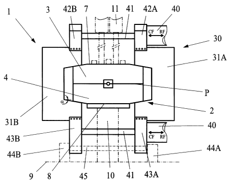
With specific reference to figs. lA-C an exemplifying embodiment of the tool
assembly 1
according to the invention will now be described in an application intended
for a hydro-
CA 02391554 2002-05-15
WO 01/36123 PCT/SE00/02235
8
forming apparatus. In this embodiment the hydroforming apparatus comprises a
tool assembly
1 consisting of a forming tool 2 having a lower tool section 4 and an upper
tool section 3.
With reference to figs. 3 and 4, the tool sections 3, 4 have mating inner
surfaces 6 and 5,
respectively, forming a parting plane P of the tool assembly. At an outer
surface 8 the lower
tool section 4 is supported on a support surface 9 by a schematically
illustrated base 10. The
lower tool section 4 may be firmly attached to or movably supported (see
further below) on
the base 10. The base may be of any conventional type, such as a frame or a
solid base. The
upper tool section 3 is supported so as to be movable relative to the lower
tool section 4. In
the illustrated embodiment the upper tool section is movable in a generally
vertical direction
by means of lifting cylinders 11 (indicated in fig. 1A) connected to an outer
surface 7 thereof.
Figs. 1 B and 1 C indicate that in a modified variant the lower tool section 4
is movably
supported on wheels 10a running on rails l Ob attached to the base 10, so that
it will be rolled
out from underneath the upper tool section once the initial opening of the
tool 2 has been
L 5 performed. These functions may be performed using conventional supporting
means and
actuators, such as rails and hydraulic cylinders, since they will only have to
carry the weight of
the individual tool section. In the closed position, during the hydroforming
process no
additional forces are applied to such supporting means, since the later
described tool clamps
or closing force application clamps 31A, 31B and actuators 40 according to the
invention take
'_ 0 up all forces related to the hydroforming process. With this alternative
configuration the
loading and unloading of workpieces may be performed with full, unrestricted
access to the
lower tool section 4, and it is therefore well suited for a robot application.
In an alternative that is not specifically illustrated, the upper tool section
3 will be supported in a
'. 5 frame and opening of the tool 2 is performed by lowering the lower tool
section 4 slightly in a
supporting carrier movable on the rails 10a. A further alternative embodiment
of the movable
support of the upper tool section 3 is illustrated in fig. 7, and will be
described further below.
In the illustrated embodiment the tool assembly 1 is designed for an internal
hydroforming
0 process, in which tubular workpieces are formed by means of pressurized
fluid applied to an
inner cavity of a blank B (see fig. 1 C). For this type of process the upper
and lower tool sections
3, 4 are each provided with a recess 12 and 13 respectively, in their inner,
mating surfaces 5. 6
CA 02391554 2002-05-15
WO 01/36123 PCT/SE00/02235
9
(see figs. 3 and 4). The recesses 12, 13 are extended over the full length of
the tool sections 3, 4
and receive upper and lower die sections 14 and 15 respectively. The die
sections 14, 15 in
themselves as well as their connection to the tool sections 3, 4 do not form
any part of the
present invention, and are therefore only illustrated very schematically and
will not be described
in any detail. It should be obvious that the invention may be used together
with and modified for
any applicable type of conventional die. In the conventional manner the die
sections 14. 15
together form a die cavity C (see figs. 3 and 4) when the tool 2 is in its
closed position. The die
cavity C receives a blank B to be processed in the apparatus l, and in the
conventional manner
the blank B extends out of the tool 2 with both of its ends (see fig. 1 C).
Fig. 1 C also schematically illustrates the conventionally used end feed
cylinders 16, 17 through
which the pressurized fluid is introduced into the inner cavity of the blank
B, and by means of
which blank material is fed into the die cavity to compensate for the
expansion of the blank B
against the cavity walls. At the free end of their rod, the end feed cylinders
16, 17 cant' a cone
L 5 that is forcibly introduced into the inner cavity of the blank in order to
expand the blank ends
and to provide a seal against the introduced fluid, and in order to perform
the above mentioned
feeding of blank material, as is well known within this technique.
At their outer surfaces 7, 8 the tool sections 3, 4 are provided with inclined
clamp contact
0 surfaces or closing force application surfaces 20, 21, 22, 23, provided one
along each of two
opposite sides 24, 25, 26 and 27 respectively, of the tool sections 3, 4
(figs. 3 and 4). All of the
closing force application surfaces 20, 21, 22, 23 are inclined so as to slope
outwardly towards
the associated side of the respective tool section, and they are all inclined
with the same acute
angle a relative to the inner surface of the associated tool section, and
thereby to the parting
'.5 plane P. The described closing force application surfaces 20, 21, 22, 23
may each extend along
the entire, associated tool section sides 24, 2~, 26 and 27 respectively, as
is illustrated in fig. 1 C,
but may likewise extend only along a portion or portions of said sides,
corresponding to the
extent of the associated, below described tool contact surfaces 32, 33 of a
closing force
application unit 30.
0
The tool 2 is manufactured from a material suitable for withstanding the below
discussed forces
applied thereto during the hydroforming process, preferably from steel or cast
iron. Depending
CA 02391554 2002-05-15
WO 01/36123 PCT/SE00/02235
upon the chosen material for the tool 2 and/or upon the dimensions thereof,
one or more
reinforcements may be provided, as is exemplified in figs. 1 A, 1 B and 1 C
where three steel
strengthening bars 18 are provided on the upper surface 7 of the upper tool
section 3.
5 The illustrated tool 2 that is designed specifically for internal
hydroforming is only used to
exemplify the invention and the tool assembly 1 according to the invention may
be employed in
other applications for performing other forming processes operating with high
internal pressures,
such as injection molding, or for performing other hydroforming processes,
such as flexforming.
Fig. 10 illustrates a tool assembly designed for such an alternative
hydroforming process, as will
0 be described more closely below.
The tool assembly 1 further comprises closing force application units 30
comprising actuators 40
for applying the closing force to the tool 2 through tool clamps 31A, 318. In
the present
embodiment said actuators are schematically illustrated as hydraulic cylinders
being connected
5 to the tool clamps. However, it should be emphasized that other
conventional, linear actuators
could be employed within the scope of the invention, especially in
applications employing
relatively low fluid pressures for the forming process.
The tool clamps 31A, 31B are generally C-shaped having two fixed jaws 35 and
36 extending
0 outwardly from a solid base portion 34, as is illustrated in fig. 1B and in
greater detail in fig. 6.
The tool clamps 31A, 31B are positioned adjacent each of the two opposite
sides 24, 25 (fig. 1C)
of the tool 2, with the open C-shape facing the tool 2. The jaws 35 and 36 are
appropriately
spaced apart to allow the closed tool 2 to be introduced between said jaws
when the actuators 40
are activated. To allow the clamp jaws 35, 36 to grip a tool 2 properly from
the outside, the
inner, generally facing tool contact surfaces 32, 33 of the jaws 35 and 36
respectively, are
inclined at an angle a relative to the working direction CF-RF of the
actuator, i.e. the direction in
which the actuator 40 applies the closing force CF to the tool 2 and the
return force RF to retract
the clamp 31 A, 31 B from the tool 2. This direction CF-RF in which the
actuator 40 applies its
force is substantially parallel to the parting plane P of the tool 2 and the
angle of inclination a of
the clamp surfaces 32, 33 is equal to that of the closing force application
surfaces 20, 21, 22, 23
on the tool sections 3, 4. In the clamped condition, a considerable portion of
the clamp jaws 35,
CA 02391554 2002-05-15
WO 01/36123 PCT/SE00/02235
11
36 will grip the tool assembly from the outside and will counteract the
separating forces
generated by the fluid pressure and acting against the tool sections, as will
be described.
Thanks to the cooperating wedge shaped surfaces 20-23 and 32,33 on the tool
sections 3, 4 and
on the clamp jaws 35, 36, separation of the tool sections can be effectively
counteracted by
appropriate regulation of the closing force CF applied by the actuators 40, to
secure that the
applied closing force always exceeds the portion of the tool separating force
that is not taken up
by the clamp material. In other words, in the preferred embodiment of the
invention the actuators
are activated to apply the closing force CF to the tool during the entire
forming process.
0
In the illustrated embodiment two pairs of tool clamps 31A, 31B are provided
for each tool 2,
each such pair comprising two opposed clamps 31 A, 31 B provided at the
respective side 24, 26
and 2~, 27 respectively of the tool 2. In the illustrated embodiment two
actuators 40 operate each
pair of tool clamps. The actuators 40 are connected to the clamps 31A, 31B,
and in particular so
5 as to apply the closing force in the area of the outer free ends of the jaws
35, 36. Specifically, in
the illustrated embodiment the rod ends of the hydraulic cylinders 40 are
attached to first clamp
attachments 42A, 43A secured to the outwardly facing side of the respective
clamp jaw 35, 36 of
a first clamp 31A. The piston rods 41 of the actuators 40 span the tool 2 and
their free outer ends
41A are in turn connected to second clamp attachments 42B, 43B secured to the
outwardly
0 facing side of the respective clamp jaw 35, 36 of a second, opposite clamp
31B. Therefore, it
will now be obvious that retraction of the piston rods 41 will cause the
opposing clamps 31A,
31 B to move towards each other to thereby engage the tool 2 and apply the
closing force. Like-
wise. extending the piston rods 41 will cause the clamps to move apart,
disengaging the tool 2.
5 Figs. 1A and 1B illustrate that the clamp attachments 42A-B and 43A-B are
secured to the outer
sides of the free ends of the clamp jaws 35 and 36 respectively. This
configuration is favorable
to eliminate outward flexing of the jaws caused by the internal pressure in
the tool during a
forming process, and is essential in applications with very high internal tool
pressures, as will be
described further in connection with fig. 6.
0
Figs. 1 A and 1 B illustrate schematically that each pair of clamps 31 A, 31 B
of the closing force
application units 30 are individually movable, by being supported on one or
several guide rods
CA 02391554 2002-05-15
WO 01/36123 PCT/SE00/02235
12
45. The guide rods 45 extend through the lower part of the second clamp
attachments 43A, 43B
of each clamp pair, being slidably received therein by means of appropriate
slide bearings (not
illustrated). The ends of the slide rods 45 are secured in stands 44A, 44B
fixed to the support
surface 9.
In the illustrated embodiment each closing force application unit 30 comprises
two pairs of
mutually opposite clamps 31A, 31B with their respective actuators 40. Said
pairs are positioned
at a distance from each other along the tool 2. It should be emphasized that
the number of clamp
pairs for each closing force application unit 30 and/or the size of the actual
clamps and actuators
L 0 depends upon the actual application, such as the magnitude of the forming
pressure, the size of
the workpiece and of the tool 2. This will be evident when regarding the
modular arrangement
illustrated in figs. 8 and 9.
Fig. 2 illustrates an example of a practical configuration of a closing force
application unit 30' of
L 5 the embodiment illustrated in figs. 1 A-C. In said drawing figure the co-
rresponding parts have
been given the same reference designations as in figs. 1 A-C, but with the
addition of a prim
index.
Figs. 5A and SB illustrate a further developed embodiment of the tool sections
3, 4 and a clamp
'.0 31A, where measures have been taken to reduce the friction between their
inclined surfaces 20-
23 and 32,33, and thus the wear of said surfaces. Specifically, a hardened
steel plate 19 is
illustrated, recessed in the upper tool section surface 21 so that its upper
surface is at a level with
the surface 21. Similar steel plates are recessed in all of the inclined
surfaces of the tool sections,
although not illustrated. Moreover, a similar plate 50 consisting of a
synthetic composite
' 5 material is recessed in each of the inner, generally facing tool contact
surfaces 32, 33 of the
clamp 31A, although only illustrated for the upper contact surface 32 in figs.
5A and SB. In this
case the surface of the composite plate 50 is slightly raised, in the order of
a few millimeters,
above the inner surface 32.
0 Finally, figs. 5A and SB illustrate a recess 39 provided at the inner corner
of the clamp 31A,
where the jaw 35 meets the base portion 34. This is a preferred manner of
providing an
CA 02391554 2002-05-15
WO 01/36123 PCT/SE00/02235
13
improved stress distribution in this critical area of the clamp material, with
regard to the forces
applied thereto during its clamping action.
The operation of the tool assembly 1 in a hydroforming operation will now be
described. To
begin the operation, the upper tool section 3 is lifted by means of the
lifting cylinders 11. With
the lower tool section exposed a blank B is positioned in the die cavity C of
the lower die section
15, or alternatively, in the case that a new workpiece is to be formed, the
upper and lower die
sections 14, 15 are exchanged. When this work is completed the upper tool
section 3 is lowered
down onto the lower tool section 4 with the blank received in the cavity C.
The closing force
application units 30, that is their actuators 40, are then simultaneously
activated to retract the
rods 41 until the tool clamps 31 A, 31 B engage the inclined clamp contact
surfaces 20-23 on the
tool sections 3, 4 with their inclined tool contact surfaces 32, 33. The
closing force CF applied
by the actuators 40 is adjusted by regulating the hydraulic working fluid
supplied thereto, said
regulation being performed in any conventional manner.
The required closing force is determined primarily by the magnitude of the
hydroforming fluid
pressure applied inside the blank B, the size of the blank and of the tool 2
and by the value of the
angle of inclination a of the surfaces 20-23 and 32, 33. The forming fluid
pressure generates,
through the blank B being pressed against the walls of the dies 14, 15, an
out,vardly directed
0 normal force Ftooi in each of the inclined tool surfaces 20-23, counteracted
by a force in the
clamp surfaces 32, 33 generated by the force CF supplied by the actuators 40.
Since the angle a
is acute, i.e. less than 90°, the material of the clamp 31A, 31B,
through the tool contact surfaces
32, 33, takes up a portion or component of this normal force and only a
remaining portion or
component thereof has to be counteracted by the closing force CF applied by
means of the
'. 5 actuators 40. Thus, according to the invention, the size and complexity
of the actuators 40 can be
reduced. Any expansion, i.e. widening of the clamp jaws 35, 36 is
automatically compensated
for by a further retraction of the actuator rods 41, so that a firm contact is
always maintained
between the inclined surfaces 20-23 and 32, 33. This will secure that no
separation of the tool
sections 3, 4 will be possible.
0
As mentioned above the actual required closing force CF is partly determined
by choosing the
value of the angle a. In order to avoid any danger of locking the clamps 31A,
31B to the tool 2,
CA 02391554 2002-05-15
WO 01/36123 PCT/SE00/02235
14
like with a conventional tapered tool shank, the angle a, should be chosen so
as to be at least 3°,
preferably at least 7°. On the other hand, to provide a significant
reduction of the actuator size
and complexity, the angle a should be chosen less than 45°, so that the
major portion of the
separating force will be taken up by the clamp material and only a smaller
portion has to be
counteracted by the closing force. At present it is believed that the best
overall results will be
obtained by choosing said angle a to be between 12° and 6°,
preferably 10°. As an example,
with the angle a, being 10° the required closing force CF will be less
than approximately 20% of
the closing force required in a conventional vertically operating press.
With the tool 2 clamped in the described manner, the hydroforming pressurized
fluid is
introduced into the blank B in the conventional manner, through the end feed
cylinders 17. The
blank B is normally preformed at a relatively low pressure, before the full
fluid pressure is
applied to expand the blank B so that it receives the shape of the inner die
walls. These steps are
all conventional within the hydroforming technique, and will not be described
in any detail.
Once the forming operation is completed, the actuators 40 are activated in the
opposite direction,
to extend their rods 41 and remove the clamps 31 A, 31 B from the tool 2. The
tool may now be
opened for the unloading and loading work, preferably after the lower tool
section 4 has been
rolled to one side on the rails 10b. Finally the lower tool section 4 is
rolled back in under the
upper tool section 3, the tool 2 is closed and a new forming cycle can begin.
Fig 6 illustrates an upper half of a clamp 31A with its base 34 and upper jaw
35. It will be seen
therefrom that for the purposes of this description the base portion 34 of the
clamp 31A only
comprises the central portion between the jaws 35, 36. Thus, the jaws (only
the upper one
illustrated in fig. 6) make out the complete outer part of the clamp,
including all of the areas F1-
F4 of fig. 6.
In applications employing very high internal pressures in the tool 2 during
forming operations it
has been found to be essential to apply the closing force CF to the clamps 2
in the area of the
jaws 35, 36. This is done to counteract the tendency of the jaws to deflect
outwardly under the
influence of the outwardly directed normal force Fr°°i in each
of the inclined tool surfaces 20-23.
which might occur if the closing force CF was applied to the clamp 2 in the
area of the basic
portion 34. In other words, applying the closing force CF to the clamp in any
of the areas Fl-F4
of the jaw 35 will provide a counter-clockwise moment M - with regard to the
illustration in fig.
CA 02391554 2002-05-15
WO 01/36123 PCT/SE00/02235
6 - around the point PR. Such a moment M will effectively counteract any
outward deflection of
the jaw 35 caused by the force Fcooi from the tool 2. The desired size of this
counteracting
moment M can be chosen, depending upon the internal pressure of the tool and
the dimensions
as well as the material of the tool and of the clamp, by applying the closing
force CF to different
5 areas F1-F4 of the jaws. This is illustrated very schematically in fig. 6 by
means of the areas F1-
F4, where the largest moment M is provided with the closing force applied
approximately in the
area F3. The produced moment then gradually decreases as the point of
application is moved to
the area F2, then to F4 and will be smallest in the area F 1. Naturally the
areas F 1-F4 are only
chosen in order to illustrate the general principle. In reality the applied
moment varies gradually
0 from point to point in the jaw 35.
Fig. 7 illustrates an alternative structure for providing the relative
movement between the tool
sections 103. 104 of a tool 102. Specifically fig. 7 illustrates an opening
sequence for the tool,
after a performed workpiece W forming process. Like in the first embodiment,
the lower tool
5 section 104 is supported on a support surface 9 by a supporting base 10. To
the supporting base
10 is also attached a frame 172 carrying three hydraulic cylinders 161, 162,
163 employed to
open and close the tool 102. A first lifting cylinder 161 is firmly connected
to the frame 172 at
its rear end, as is indicated at 164. The rod end of the first cylinder 161 is
pivotally connected to
a first side of the upper tool section 103 through a conventional joint, as
indicated at 165.
0 A second lifting cylinder 162 is likewise firmly connected to the frame 172
at its rear end, as is
indicated at 166. The rod end of the second lifting cylinder 162 carries a
lifting plate 167 at its
rod end. This lifting plate 167 contacts a lifting support 168 on the
opposite, second side of the
upper tool section 103 during the initial phase of the lifting movement but is
not connected
thereto. Finally, with its rear end a third cylinder 163 is pivotally
supported in a cylinder mount
5 170 on the frame 172, as is indicated at 169. At its rod end the third
cylinder 163 is pivotally
connected to the upper tool section 103, likewise through a conventional joint
171, and at a
position spaced apart upwardly from the pivotal joint 165 of the first
cylinder 161.
To the left in fig. 7 the tool is illustrated in a position with the upper
tool section 103 resting on
the lower tool section 104 in the parting plane P, such as after a forming
cycle. In this position,
the first and second lifting cylinders 161, 162 are activated to raise the
upper tool section 103
straight upwardly from the lower tool section 104, as is indicated in the
middle drawing of fig. 7.
CA 02391554 2002-05-15
WO 01/36123 PCT/SE00/02235
16
During this sequence the third cylinder 163 is totally relieved so that its
rod will be extended due
to the raising of the upper tool section 103. Next, the rod of the third
cylinder 163 is retracted.
This will swing the upper tool section 103 in a counter clockwise direction
around a pivot
formed by the pivotal joint 165, to the fully open position illustrated to the
right in fig. 7.
Maneuvering the cylinders in the reverse sequence carries out the lowering of
the upper tool
section 103 down onto the lower tool section 104. The lifting arrangement
illustrated in fig. 7
provides excellent access to the tool 102, since it leaves the space above the
tool totally free for
loading, unloading and service work in the open tool condition, even more so
if it is combined
with the wheels 10a and rails l Ob (illustrated in the middle of fig. 7)
according to the modified
alternative of the first embodiment, so that the lower tool section 104 may be
rolled out from the
closing position for the loading and unloading. The closing force application
unit has been ex-
cluded in the illustration of fig. 7. However, this embodiment of the tool 102
requires a modified
variant of said closing force application unit, since the swinging movement of
the upper tool
section 103 would interfere with the actuator rods in the first embodiment of
the closing force
application unit 30 illustrated in figs. lA-C and 2. However, fig. 12
illustrates such a modified
closing force application unit, as will be described further below.
Figs. 8 and 9 illustrate a further application of the principles of the
invention to a hydroforming
apparatus in a specific modular arrangement suitable for forming long
workpieces W that have a
0 shape with several, relatively large bends in two planes. This embodiment
illustrates the
versatility that may be accomplished for a hydroforming apparatus employing
tool assemblies
201 according to the invention. Tools 202A-C of different length are provided
in an end-to-end
relationship. The individual tools 202A-C are identical to the one illustrated
in figs. 1A, 1B and
1 C, only shorter, tools 202B-C, and/or provided with end faces inclined to
accommodate said
'. 5 bends of the workpiece W, in one or both of the two planes. As indicated
in fig. 8, closing force
application units 230A, 230B having at least one pair of clamps 231A, 231B and
at least two
actuators 240A, 240B are provided for each tool assembly 202A-C of the line.
Said closing force
application units, clamps and actuators are only schematically illustrated,
but in this case each
clamp is carried by only one actuator connected to the base portion of the
clamp. Such a
0 configuration is only appropriate for applications with moderate internal
tool pressures, as
described above. In other applications the closing force application units and
actuators may
preferably correspond to those of the first embodiment, with the exception
that smaller sized
CA 02391554 2002-05-15
WO 01/36123 PCT/SE00/02235
17
closing force application units 230B and actuators 240B are provided for the
shorter tool
assemblies 202B-C. Fig 8 is a schematical top plan view of the hydroforming
apparatus, whereas
fig. 9 is a corresponding side view, but with the actuators removed, to
illustrate the bends in the
second plane.
Fig 10 illustrates a further embodiment of a tool 302 for use with the
invention, designed as a
flexforming tool. In a flexforming tool 302 the lower tool section 304
receives a die 315 having
its inner wall matching the shape of the finished workpiece and forming the
die cavity C. The
upper tool section 303 has a pressure fluid cavity 314 closed downwardly by a
rubber membrane
300 lying substantially in the parting plane P of the closed tool 302. A blank
B in the form of a
metal plate is placed on the lower tool section 304, the upper tool section
303 with the
membrane 300 is lowered down onto the lower tool section 304, and actuators
(not shown) are
activated to move their associated closing clamps 31A to the closing position.
Like in the
previous embodiment the tool clamp surfaces 32 and 33 are brought into
engagement with the
corresponding surfaces 321 and 323 on the upper and lower tool sections 303,
304. Then
pressurized fluid is introduced into the pressure fluid cavity 314 in a manner
that is not
specifically illustrated, but that is well known in the art. The pressurized
fluid, through the
rubber membrane 300, forces the blank B into the die 315 to receive its final
shape, as is
conventional.
?0
Fig. 11 illustrates a further developed embodiment of an actuator tool clamp
531A. In this
embodiment the tool clamp is made up of a number of, in the illustrated
embodiment five,
parallel plates 551 attached to each other in an arrangement side-by-side.
This results in a very
strong and wear resistant clamp 531A, specifically so in combination with the
inserts illustrated
5 in figs. 5 and 6. In the drawing figure is also schematically illustrated
how the clamp attachments
542A, 543A are secured to the actual clamp 531A. Two recesses 537 are formed
in each of the
upper and lower, outer surfaces of the clamp, and are spaced apart so as to
leave a raised portion
538 therebetiveen. The attachments 542A, 542B are provided with a
complementary shape, and
are fastened to the clamp by means of bolts (not illustrated) introduced into
schematically illu
> 0 strated bores 538A in the attachments and in the clamp.
CA 02391554 2002-05-15
WO 01/36123 PCT/SE00/02235
18
Finally, fig. 12 illustrates a further embodiment of a tool assembly 401 of
the invention,
specifically suited for applications where a free space must be provided above
and below the
tool 2, such as with the tool lifting equipment illustrated in fig. 7. In this
case the closing force
application unit 430 comprises four actuators 440 for the pair of clamps 431A,
431B. In other
words, the closing force CF is applied separately to each clamp 431 A or 431 B
of a pair by
means of two actuators 440. In this embodiment the actuators 440 are supported
separate from
the clamps and carry the clamps at the free ends of their piston rods 441
through the clamp
attachments 442A-B, 443A-B.
Although the invention has been described herein with specific reference to
hydroforming
applications, it shall be emphasized that the invention in its basic scope
covers airy application
where a high internal pressure is employed between forming tool halves, such
as in injection
molding where die sections are provided in at least one tool section for
receiving pressurized
material intended for forming an article.
It will be understood by those skilled in the art that various other
modifications and changes may
be made to the present invention without departure from the scope thereof,
which is defined by
the appended claims.