Language selection

Search

Patent 2391584 Summary

Third-party information liability

Some of the information on this Web page has been provided by external sources. The Government of Canada is not responsible for the accuracy, reliability or currency of the information supplied by external sources. Users wishing to rely upon this information should consult directly with the source of the information. Content provided by external sources is not subject to official languages, privacy and accessibility requirements.

Claims and Abstract availability

Any discrepancies in the text and image of the Claims and Abstract are due to differing posting times. Text of the Claims and Abstract are posted:

  • At the time the application is open to public inspection;
  • At the time of issue of the patent (grant).
(12) Patent: (11) CA 2391584
(54) English Title: METHOD FOR EXPANDING A TUBULAR ELEMENT IN A WELLBORE
(54) French Title: PROCEDE D'ELARGISSEMENT D'UN ELEMENT TUBULAIRE DANS UN PUITS DE FORAGE
Status: Expired
Bibliographic Data
(51) International Patent Classification (IPC):
  • E21B 43/10 (2006.01)
(72) Inventors :
  • WIJSMAN, CORNELIS JACOBUS (Netherlands (Kingdom of the))
(73) Owners :
  • SHELL CANADA LIMITED (Canada)
(71) Applicants :
  • SHELL CANADA LIMITED (Canada)
(74) Agent: SMART & BIGGAR LLP
(74) Associate agent:
(45) Issued: 2008-09-23
(86) PCT Filing Date: 2000-11-15
(87) Open to Public Inspection: 2001-05-25
Examination requested: 2005-10-17
Availability of licence: N/A
(25) Language of filing: English

Patent Cooperation Treaty (PCT): Yes
(86) PCT Filing Number: PCT/EP2000/011551
(87) International Publication Number: WO2001/036788
(85) National Entry: 2002-05-14

(30) Application Priority Data:
Application No. Country/Territory Date
99203814.1 European Patent Office (EPO) 1999-11-15

Abstracts

English Abstract


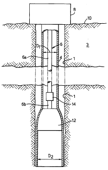
A method of expanding a tubular element (4) in
a borehole comprising installing the tubular element at a selected
location in the borehole, installing a pulling string (6) in the
bore--hole, the pulling string having an upper part (6a) connected to the
pulling device (8) at surface and a lower part (6b) provided with
an expander (12) of outer diameter larger than the inner diameter
of the tubular element, the expander being arranged below at least
part of the tubular element to be expanded, the upper part being
connected to the lower part by a connector (14) allowing rota-tion
of the upper part relative to the lower part, and pulling the
expander through said at least part of the tubular element by
oper-ating the pulling device so as to pull the pulling string in upward
direction, and simultaneously rotating said upper part relative to
said lower part.


French Abstract

L'invention traite d'un procédé permettant d'élargir un élément tubulaire (4) dans un puits de forage. Ce procédé consiste à installer l'élément tubulaire dans l'emplacement sélectionné dans le puits de forage, à installer dans le puits un train de tubage (6) dont la partie supérieure (6a) est reliée à un dispositif de traction (8) en surface et la partie inférieure (6b) est pourvue d'un dispositif élargisseur (12) dont le diamètre extérieur est supérieur au diamètre intérieur de l'élément tubulaire. Le dispositif élargisseur est placé en dessous d'au moins une partie de l'élément tubulaire à élargir. La partie supérieure du train de tubage est reliée à la partie inférieure de ce dernier par un connecteur (14) permettant la rotation de la partie supérieure par rapport à la partie inférieure. Ce procédé consiste ensuite à tirer le dispositif élargisseur de manière à tirer le train de tubage en actionnant le dispositif de traction pour tirer le train de tubage vers le haut, tout en assurant la rotation simultanée de ladite partie supérieure par rapport à ladite partie inférieure.

Claims

Note: Claims are shown in the official language in which they were submitted.


-5-

CLAIMS

1. A method of expanding a tubular element in a borehole
formed in an earth formation, the method comprising:
- installing the tubular element at a selected location
in the borehole;
- installing a pulling string in the borehole, the
pulling string extending in longitudinal direction
through the tubular element and having an upper part
connected to a pulling device at surface and a lower part
provided with an expander of outer diameter larger than
the inner diameter of the tubular element, the expander
being arranged below at least part of the tubular element
to be expanded, the upper part being connected to the
lower part by a connector allowing rotation of the upper
part relative to the lower part about the longitudinal
axis of the pulling string; and
- pulling the expander through said at least part of
the tubular element by operating the pulling device so as
to pull the pulling string in upward direction, and
simultaneously rotating said upper part relative to said
lower part.
2. The method of claim 1, wherein the connector is
arranged adjacent the expander.
3. The method of claim 1 or 2, wherein the connector is
selectively operable in an engaged mode wherein said
rotation of the upper part relative to the lower part is
prevented, and a disengaged mode wherein said rotation of
the upper part relative to the lower part is allowed.
4. The method of any one of claims 1-3, wherein said
tubular element is selected from a wellbore casing, a
wellbore screen and a wellbore liner.


-6-

5. The method of any one of claims 1-4, wherein the
pulling string is a drill string for drilling the
borehole.

Description

Note: Descriptions are shown in the official language in which they were submitted.


CA 02391584 2007-10-03
63293-3875

METHOD FOR EXPANDING A TUBULAR ELEMENT IN A WELLBORE
The present invention relates to a method of
expanding a tubular element in a borehole formed in an
earth formation. In the technology of borehole drilling
for the exploitation of hydrocarbon fluids, the borehole
is generally provided with a casing or liner to prevent
collapse of the borehole wall. It has already been tried
to apply radially expandable casings or liners, whereby
the casing/liner is lowered into the borehole and
thereafter radially expanded by pulling an expander
through the casing/liner.. One of the advantages of such
procedure is that there is no longer a need for the
conventional nested arrangement of borehole casings of
stepwise decreasing diameter-. However it has appeared
that the pulling force necessary to pull the expander
through the casing/liner can be prohibitively high.
It is an object of some embodiments to provide an
improved method of expanding a tubular element in a
borehole formed in an earth formation, whereby the
pulling forces needed to pull an expander through the
tubular element are reduced.
In accordance with the inventionthere is provided a
method of expanding a tubular element in a borehole
formed in an earth formation, the method comprising:
- installing the tubular element at a selected location
in the borehole;
- installing a pulling string in the borehole, the
pulling string extending in longitudinal direction
through the tubular element and having an upper part
connected to a pulling device at surface and a lower part
provided with an expander of outer diameter larger than
the inner diameter of the tubular element, the expander


CA 02391584 2002-05-14

WO 01/36788 - 2 - PCT/EP00/11551
being arranged below at least part of the tubular element
to be expanded, the upper part being connected to the
lower part by a connector allowing rotation of the upper
part relative to the lower part about the longitudinal
axis of the pulling string; and
- pulling the expander through said at least part of
the tubular element by operating the pulling device so as
to pull the pulling string in upward direction, and
simultaneously rotating the upper part of the pulling
string relative to the lower part thereof.
By simultaneously pulling the string and rotating the
upper part of the string it is achieved that the
longitudinal component of friction between the string and
the borehole wall or tubular element, is significantly
reduced or even eliminated. Consequently the pulling
force no longer needs to counteract said longitudinal
friction component.
The invention will be further described in more
detail and with reference to the accompanying drawing in
which Fig. 1 schematically shows an embodiment of a pull
string used in application of the method according to the
invention.

In Fig. 1 is shown a borehole 1 formed in an earth
formation 3. A tubular casing 4 having an initial
internal diameter Dl is installed in the borehole 1 to a
selected depth. The casing 4 extends from the selected
depth to surface (as shown in Fig. 1). Alternatively the
casing 4 extends from the selected depth to a location
below surface. A pulling string in the form of a drill
string 6 having a longitudinal fluid passage (not shown)
extends through the borehole 1 and into the casing 4, the
drill string 6 having an upper part 6a connected to a
pulling device 8 arranged at the earth surface 10 and a
lower part 6b connected to an expander 12. The
expander 12 has a frustoconical shape with an upper end


CA 02391584 2002-05-14

WO 01/36788 - 3 - PCT/EP00/11551
of diameter slightly smaller than D1 and a lower end of
diameter D2 larger than D1. Furthermore the expander 12
is provided with a first latching device (not shown) for
temporarily latching the expander 12 to the lower end of
the casing 4, and with a second latching device (not
shown) for latching the lower end of the drill string 6
to the expander 12. The pulling device 8 is capable of
pulling the drill string 6 in upward direction through
the borehole 1.

The upper part 6a of the drill string 6 is connected
to the lower part 6b thereof by a connector in the form
of a clutch 14 operable in an engaged mode in which the
clutch 14 prevents rotation of the upper part 6a relative
to the lower part 6b about the longitudinal axis of the
drill string 6, and a disengaged mode in which the
clutch 14 allows rotation of the upper part 6a relative
to the lower part 6b about said longitudinal axis. The
clutch 14 can be controlled to switch between the engaged
mode and the disengaged mode by selected pressure pulses
induced in a body of fluid present in the fluid passage
of the drill string 6, or by any other control means, for
example electrical control means.
During normal operation the expander 12 is latched to
the lower end of the casing 4, and the casing 4 with the
expander latched thereto is lowered through the
borehole 1 until the lower end of the casing arrives at
the selected depth whereupon the casing 4 is anchored to
the borehole. Next the drill string 6 is lowered through
the casing 4 until the lower end of the drill string 6
latches to the expander 12, whereby during lowering of
the drill string 6 the clutch 14 is in the engaged mode.
The clutch 14 is then switched to the disengaged mode,
and the upper part 6a of the drill string 6 is rotated
while simultaneously the pulling device 8 is operated so


CA 02391584 2002-05-14

WO 01/36788 - 4 - PCT/EP00/11551

as to pull the drill string 6 in upward direction through
the borehole 1. The expander 12 is thereby unlatched from
the lower end of the casing 4 and is pulled through the
casing 4 in upward direction thereby expanding the
casing 4 to inner diameter D2.

By simultaneously pulling the drill string 6 and
rotating the upper part 6a thereof it has been achieved
that the pulling force necessary to pull the string
through the borehole is significantly reduced by virtue
of a reduction of (or the absence of) the longitudinal
component of the friction between the upper part 6a and
the casing/borehole wall.

Representative Drawing
A single figure which represents the drawing illustrating the invention.
Administrative Status

For a clearer understanding of the status of the application/patent presented on this page, the site Disclaimer , as well as the definitions for Patent , Administrative Status , Maintenance Fee  and Payment History  should be consulted.

Administrative Status

Title Date
Forecasted Issue Date 2008-09-23
(86) PCT Filing Date 2000-11-15
(87) PCT Publication Date 2001-05-25
(85) National Entry 2002-05-14
Examination Requested 2005-10-17
(45) Issued 2008-09-23
Expired 2020-11-16

Abandonment History

There is no abandonment history.

Payment History

Fee Type Anniversary Year Due Date Amount Paid Paid Date
Registration of a document - section 124 $100.00 2002-05-14
Application Fee $300.00 2002-05-14
Maintenance Fee - Application - New Act 2 2002-11-15 $100.00 2002-10-03
Maintenance Fee - Application - New Act 3 2003-11-17 $100.00 2003-09-05
Maintenance Fee - Application - New Act 4 2004-11-15 $100.00 2004-10-18
Maintenance Fee - Application - New Act 5 2005-11-15 $200.00 2005-09-29
Request for Examination $800.00 2005-10-17
Maintenance Fee - Application - New Act 6 2006-11-15 $200.00 2006-10-04
Maintenance Fee - Application - New Act 7 2007-11-15 $200.00 2007-09-21
Final Fee $300.00 2008-07-07
Maintenance Fee - Patent - New Act 8 2008-11-17 $200.00 2008-10-06
Maintenance Fee - Patent - New Act 9 2009-11-16 $200.00 2009-10-16
Maintenance Fee - Patent - New Act 10 2010-11-15 $250.00 2010-10-13
Maintenance Fee - Patent - New Act 11 2011-11-15 $250.00 2011-09-22
Maintenance Fee - Patent - New Act 12 2012-11-15 $250.00 2012-09-27
Maintenance Fee - Patent - New Act 13 2013-11-15 $250.00 2013-10-09
Maintenance Fee - Patent - New Act 14 2014-11-17 $250.00 2014-10-22
Maintenance Fee - Patent - New Act 15 2015-11-16 $450.00 2015-10-21
Maintenance Fee - Patent - New Act 16 2016-11-15 $450.00 2016-10-26
Maintenance Fee - Patent - New Act 17 2017-11-15 $450.00 2017-10-25
Maintenance Fee - Patent - New Act 18 2018-11-15 $450.00 2018-10-24
Maintenance Fee - Patent - New Act 19 2019-11-15 $450.00 2019-10-23
Owners on Record

Note: Records showing the ownership history in alphabetical order.

Current Owners on Record
SHELL CANADA LIMITED
Past Owners on Record
WIJSMAN, CORNELIS JACOBUS
Past Owners that do not appear in the "Owners on Record" listing will appear in other documentation within the application.
Documents

To view selected files, please enter reCAPTCHA code :


To view images, click a link in the Document Description column. To download the documents, select one or more checkboxes in the first column and then click the "Download Selected in PDF format (Zip Archive)" or the "Download Selected as Single PDF" button.

List of published and non-published patent-specific documents on the CPD .

If you have any difficulty accessing content, you can call the Client Service Centre at 1-866-997-1936 or send them an e-mail at CIPO Client Service Centre.


Document
Description 
Date
(yyyy-mm-dd) 
Number of pages   Size of Image (KB) 
Representative Drawing 2002-05-14 1 20
Cover Page 2002-10-23 1 44
Claims 2002-05-14 2 44
Abstract 2002-05-14 1 63
Drawings 2002-05-14 1 19
Description 2002-05-14 5 155
Description 2007-10-03 4 149
Claims 2007-10-03 2 41
Representative Drawing 2008-09-10 1 10
Cover Page 2008-09-10 2 48
PCT 2002-05-14 8 300
Assignment 2002-05-14 3 136
Prosecution-Amendment 2007-04-13 2 34
Prosecution-Amendment 2005-10-17 1 36
Prosecution-Amendment 2007-10-03 4 95
Correspondence 2008-07-07 1 38