Language selection

Search

Patent 2392021 Summary

Third-party information liability

Some of the information on this Web page has been provided by external sources. The Government of Canada is not responsible for the accuracy, reliability or currency of the information supplied by external sources. Users wishing to rely upon this information should consult directly with the source of the information. Content provided by external sources is not subject to official languages, privacy and accessibility requirements.

Claims and Abstract availability

Any discrepancies in the text and image of the Claims and Abstract are due to differing posting times. Text of the Claims and Abstract are posted:

  • At the time the application is open to public inspection;
  • At the time of issue of the patent (grant).
(12) Patent: (11) CA 2392021
(54) English Title: ORTHODONTIC APPLIANCE FOR TREATING OVERJET
(54) French Title: APPAREIL ORTHODONTIQUE POUR LE TRAITEMENT DU SURPLOMB
Status: Expired
Bibliographic Data
(51) International Patent Classification (IPC):
  • A61C 7/36 (2006.01)
(72) Inventors :
  • HIGGINS, DUNCAN (Canada)
(73) Owners :
  • HIGGINS, DUNCAN (Canada)
(71) Applicants :
  • HIGGINS, DUNCAN (Canada)
(74) Agent: CAMERON, NORMAN M.
(74) Associate agent:
(45) Issued: 2004-06-22
(86) PCT Filing Date: 2000-11-15
(87) Open to Public Inspection: 2001-06-14
Examination requested: 2002-05-17
Availability of licence: N/A
(25) Language of filing: English

Patent Cooperation Treaty (PCT): Yes
(86) PCT Filing Number: PCT/CA2000/001366
(87) International Publication Number: WO2001/041669
(85) National Entry: 2002-05-17

(30) Application Priority Data:
Application No. Country/Territory Date
09/455,321 United States of America 1999-12-06

Abstracts

English Abstract


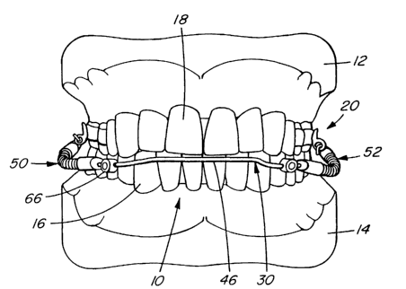
An orthodontic appliance is adapted for treating overjet in a patient having
an upper jaw, a lower jaw, lower teeth in
the lower jaw and upper teeth in the upper jaw which are abnormally forward of
the lower teeth. The teeth have lingual sides and labial
sides. The appliance includes an upper attachment device which is configured
to be secured to at least one of the upper teeth on each
side of the upper jaw. A lower attachment device has a pair of lower
connectors. Each lower connector is configured to be secured
to at least one of the lower teeth of the patient on each side of the lower
jaw. A rigid, wire-like lingual bow is extendable between the
lower connectors about the lingual sides of the lower teeth. A rigid, wire-
like labial bow is extendable between the lower connectors
about the labial sides of the lower teeth. The bows are connected to the lower
connectors. A bite jumping device interconnects each
side of the upper attachment device to a corresponding side of the lower
attachment device. Each bite jumping device includes a
first connector for connecting to the upper attachment device, a second
connector for connecting to the lower attachment device and
a biasing member which biases the lower attachment device forwardly with
respect to the upper attachment device.


French Abstract

L'invention concerne un appareil orthodontique pour le traitement du surplomb chez un patient doté d'une mâchoire supérieure, d'une mâchoire inférieure, de dents inférieures sur la mâchoire inférieure et de dents supérieures sur la mâchoire supérieure, qui se trouvent anormalement en avant par rapport aux dents inférieures. Les dents présentent des côtés linguaux et de côtés labiaux. Ledit appareil comporte un dispositif d'attache supérieur conçu pour être fixé à au moins une des dents supérieures, de chaque côté de la mâchoire supérieure. Un dispositif d'attache inférieur possède une paire de connexions inférieures. Chaque connexion inférieure est conçue pour être fixée à au moins une des dents inférieures du patient, de chaque côté de la mâchoire inférieure. Un arc lingual rigide filaire s'étend entre les connexions inférieures sur les côtés linguaux des dents inférieures. Un arc labial rigide filaire s'étend entre les connexions inférieures, autour des côtés labiaux des dents inférieures. Les arcs sont reliés aux connexions inférieures. Un élément de saut de l'articulé relie chaque côté du dispositif d'attache supérieur à un côté correspondant du dispositif d'attache inférieur. Chaque dispositif de saut d'articulé comporte une première connexion assurant la connexion au dispositif d'attache supérieur, une deuxième connexion permettant la connexion au dispositif d'attache inférieure et un élément de sollicitation qui sollicite vers l'avant le dispositif d'attache inférieur par rapport au dispositif d'attache supérieur.

Claims

Note: Claims are shown in the official language in which they were submitted.


-8-


WHAT IS CLAIMED IS:

1. An orthodontic appliance for treating overjet in a patient having a upper
jaw, a
lower jaw, lower teeth in the lower jaw and upper teeth in the upper jaw which
are abnormally forward of the lower teeth, the teeth having lingual sides and
labial sides, the appliance comprising:
an upper attachment device configured to be secured to at least one of the
upper
teeth on each side of the upper jaw;
a lower attachment device having a pair of lower connectors, each said lower
connector being configured to be secured to at least one of the lower teeth of
the
patient on each side of the lower jaw, a rigid, wire-like lingual bow
extendable
between the lower connectors about the lingual sides of the lower teeth and a
rigid, wire-like labial bow extendable between the lower connectors about the
labial sides of the lower teeth, said bows being connected to the lower
connectors;
and
a bite jumping device interconnecting each side of the upper attachment device
to a corresponding side of the lower attachment device, each said bite jumping
device including a first connector for connecting to the upper attachment
device,
a second connector for connecting to the lower attachment device and a biasing
member which biases the lower attachment device forwardly with respect to the
upper attachment device.

2. An appliance as claimed in claim 1, wherein the second connector is
connected
to the labial bow.

3. An appliance as claimed in claim 2, wherein the second connector is
adjustably
connected to the labial bow, to permit adjustment of the bite jumping device.


-9-
4. An appliance as claimed in claim 1, wherein the second connector is
slidably
connected to the labial bow.
5. An appliance as claimed in claim 4, including a stop on the labial bow to
limit
forward movement of each said bite jumping device.
6. An appliance as claimed in claim 5, wherein the stop is adjustably movable
along the
labial bow.
7. An appliance as claimed i.n claim 6,wherein the stop is an adjustable lock.
8. An appliance as claimed in claim 5, wherein the second connector has an
aperture,
the labial bow fitting slidably through the aperture in the second connector.
9. An appliance as claimed in claim 1, wherein, the bite jumping device is a
Jasper
Jumper
10. An appliance as claimed in claim 1, wherein the upper attachment device
includes
a palatal expansion appliance.
11. An appliance as claimed in claim 1, wherein each of the lower connectors
includes
a molar band.
12. An appliance as claimed, in claim 9, wherein the labial bow and the
lingual bow are
soldered to molar bands.
13. An appliance as claimed in claim 1, wherein the upper attachment device
includes
headgear tubes connected to upper molar bands.


-10-
14. An appliance as claimed in claim l,wherein the lingual bow and the labial
bow are
of stainless-steel wire.
15. An appliance as claimed in claim 12, wherein the bows are of wire
generally 1. l4mm
in diameter.

Description

Note: Descriptions are shown in the official language in which they were submitted.


CA 02392021 2002-05-17
WO 01/41669 PCT/CA00/01366
ORTHODONTIC APPLIANCE FOR TREATING OVERJET
BACKGROUND OF THE INVENTION
This invention relates to orthodontic appliances and, in particular, to
orthodontic
appliances for treating overjet in patients.
Dental over] et or overbite refers to a condition where a greater than normal
horizontal gap
exists between the upper and lower front teeth, due to proclination or flaring
of the upper
front teeth, or a deficient lower jaw. Typical treatments fall into several
categories. The
first is retracting or pushing back the upper teeth. A second is proclining or
pushing
forward the lower teeth. A further treatment is surgical lengthening of the
lower jaw.
Another treatment is orthopedic correction whereby forces on the teeth are
transmitted
to the jaws of growing children.
The term Bite Jumping is normally used to describe appliances that contact the
teeth and
hold the lower jaw forward, causing stretching of the muscles surrounding the
lower jaw.
The stretched muscles supply a force acting on the teeth and jaws to pull the
upper teeth
back, push the lower teeth forward, inhibit the upper jaw from growing forward
and
encourage the lower jaw to grow forward.
Bite Jumping appliances can be removable or nonremovable or fixed to the teeth
by
orthodontic bands or crowns and dental cement.
The Herbst appliance is an example of a fixed appliance. It uses rods and
tubes to hold
the lower jaw forward and places force on the teeth and jaws through stretched
muscles.
The Jasper jumper is a spring which connects to braces to push the upper teeth
back and
the lower teeth forward. In the past it has been used in the permanent
dentition with full
braces on the upper and lower teeth.


CA 02392021 2002-05-17
WO 01/41669 PCT/CA00/01366
-2-
Bite jumping appliances are used by some orthodontists on young patients with
mixed
dentition where baby and adult teeth are present. The appliances used are
typically of the
removable type or the Herbst style fixed type.
United States Patent Number 5,711,667 to Vogt discloses a bite jumping device
for
treating dental protrusion of the upper teeth relative to the lower teeth. It
uses braces on
the lower teeth. United States Patent Number 4,708,648 to Jasper discloses a
similar
device.
United States Patent No. 4,462,800 to Jones discloses an orthodontic bite
jumping device
having a screw at each end of telescoping members.
SUMMARY OF THE INVENTION
There is provided, according to an embodiment of the invention, an orthodontic
appliance
for treating overjet in a patient having an upper jaw, a lower jaw, lower
teeth in the lower
jaw and upper teeth in the upper jaw which are abnormally forward of the lower
teeth.
The teeth have lingual sides and labial sides. The appliance includes an upper
attachment
device configured to be secured to at least one of the upper teeth on each
side of the upper
jaw. A lower attachment device has a pair of lower connectors. Each lower
connector
is configured to be secured to at least one of the lower teeth of the patient
on each side
of the lower jaw. A rigid, wire-like lingual bow is extendable between the
lower
connectors about the lingual sides of the lower teeth. A rigid, wire-like
labial bow is
extendable between the lower connectors about the labial sides of the lower
teeth. The
bows are connected to the lower connectors. A bite jumping device
interconnects each
side of the upper attachment device to a corresponding side of the lower
attachment
device. Each bite jumping device includes a first connector for connecting to
the upper
attachment device, a second connector for connecting to the lower attachment
device and
a biasing member which biases the lower attachment device forwardly with
respect to the
upper attachment device.


CA 02392021 2002-05-17
WO 01/41669 PCT/CA00/01366
-3-
BRIEF DESCRIPTION OF THE DRAWINGS
Figure 1 is a side view of an orthodontic appliance, according to an
embodiment of the
invention, as viewed from the right side of a patient's mouth, with the
patient's jaws
closed;
Figure 2 is an elevational view of the orthodontic appliance as viewed from
the front of
the patient's mouth;
Figure 3 is a bottom plan view of the upper attachment device thereof, as
viewed on the
top set of the patient's teeth;
Figure 4 is a top plan view of the lower attachment device thereof, as viewed
on the
bottom set of the patient's teeth;
Figure 5 is a view similar to Figure 1 with the patient's jaws open;
Figure 6 is a front view thereof;
Figure 7 is a view similar to Figure 5 of an alternative embodiment of the
invention;
Figure 8 is a top plan view of the lower attachment device according to the
alternative
embodiment of the invention; and
Figure 9 is a side, isometric view thereof.
DETAILED DESCRIPTION OF THE PREFERRED EMBODIMENTS
Referring to the drawings, and first to Figures 1-6, these show an orthodontic
appliance
10 in a patient having an upper jaw 12 and a lower jaw 14. There are lower
teeth 16 in


CA 02392021 2002-05-17
WO 01/41669 PCT/CA00/01366
-4-
the lower jaw and upper teeth 18 in the upper jaw. The appliance corrects a
condition
where the upper teeth are abnormally forward of the lower teeth.
The appliance includes an upper attachment device 20 configured to be secured
to at least
one of the upper teeth on each side of the upper jaw. In this example the
upper
attachment device is a palatal expansion appliance. This embodiment is
preferred for
younger patients without a full set of permanent teeth. The attachment device
is secured
either to permanent teeth or temporary teeth which are retained relatively
late, or a
combination of both. The palatal expansion appliance is known and, therefore,
is not
described in detail. It includes bands 22 and 24 which extend about two
adjacent teeth
on each side of the jaw and an arch 25 extending therebetween.
There is a lower attachment device 30 which includes a pair of lower
connectors in the
form of bands 32 and 34 extending about molars 36 and 38 on opposite sides of
the
patient's lower jaw. There is a rigid, wire-like lingual bow 40 which extends
between the
lower connectors about the lingual sides of the lower teeth of the patient. In
this example
the lingual bow is of .045" stainless steel wire. The lingual bow is connected
to the lower
connectors, in this case by soldering. It may also be connected by tubes
similar to the
embodiment of Figures 7 and 8 described below. The lingual bow in this example
has
a pair of occlusal rests 42 and 44 which extend over the occlusal surface of
the first
bicuspid teeth. These help prevent the lingual and labial wires from moving
down and
impinging on the gum tissue.
The lower attachment device 30 also includes a rigid, wire-like labial bow 46
which
extends between the bands 32 and 34 about the labial sides of the lower teeth.
This bow
is made of stainless-steel wire in this example similar to the lingual bow.
The labial bow
is also connected to the bands 32 and 34, in this example by soldering. The
labial bow
bypasses the canine and bicuspid teeth. It contacts the incisor teeth to
prevent then from
proclining or flaring so much as to open spaces between the teeth.


CA 02392021 2002-05-17
WO 01/41669 PCT/CA00/01366
-5-
There is a bite jumping device, in this example a Jasper Jumper 50,
interconnecting the
upper attachment device and the lower attachment device on one side of the
patient's
mouth and a similar Jasper Jumper 52 interconnecting the upper attachment
device and
the lower attachment device on the opposite side of the patient's mouth.
Jasper Jumpers
are known and, accordingly, these are not described in detail. Each includes
an elongated
spring 54 which, when bent, biases the lower attachment device forwardly with
respect
to the upper attachment device. This occurs when the patient's jaws are closed
as seen
in Figures 1 and 2.
In this example each Jasper Jumper has a top eyelet 56 fitted over a wire 58
received in
a tube 60 welded to one of the bands 22 or 24. Each has a similar bottom
eyelet 62. The
labial bow extends slidably through each of the eyelets 62.
There is a stop, in the form of a Gurin lock 66 in this embodiment, on each
side of the
labial bow to limit forward movement of the Jasper Jumpers. These are known
devices
and, accordingly, are not described in detail. Each includes a cylindrical
member with an
aperture, the labial bow extending through the aperture. There is a set screw
extending
through the cylindrical member to the aperture which can be tightened to lock
the device
in a desired location on the labial bow. Accordingly, by adjusting the Gurin
locks
forwardly or rearwardly along the labial bow, the biasing force of the Jasper
Jumpers can
be reduced or increased as being desirable by the orthodontist. Each eyelet 62
slides
forwardly along the labial bow when the patient closes her or his jaws until
the eyelet
contacts the Gurin lock. Further closing of the jaws causes bending of the
springs forcing
the upper teeth backwards and the lower teeth forwardly. However opening of
the jaws
is not impeded since the eyelets can slide rearwardly along the labial bow to
a position
shown in Figure 5.
Figures 7, 8 and 9 show an alternative orthodontic appliance 70 which is
generally similar
to the previous embodiment and, accordingly, is described only with respect to
the
differences therebetween. This appliance is intended for patients who have
permanent
dentition and have been fitted with braces 72 including head gear tubes 80
welded to


CA 02392021 2002-05-17
WO 01/41669 PCT/CA00/01366
-6-
upper molar bands 81 and lip bumper tubes 110 welded to lower molar bands 112.
In this
case bite jumping device 84 is connected to the upper braces 72 in the
conventional
manner, similar to the type of connection between the previous jumping devices
and the
previous upper attachment device.
Only a portion of the device is shown in Figures 8 and 9 including lower
attachment
device 82 and Jasper Jumper 84. This variation is intended for patients who
have full
braces 90 on permanent lower dentition. In this case there is an anterior or
front curvature
91 and a canine or cuspid step out bend 92 on each side thereof on labial bow
94.
Likewise there is a molar step out bend 96 on each side located rearwardly of
each bend
92. A sliding rail portion 98 of the labial bow extends between the step out
bend 92 and
the step out bend 96. Eyelet 100 of each of the Jasper Jumpers is slidably
received on the
sliding rail portion.
A Gurin lock 102 is received on each sliding rail portion forwardly of the
Jasper Jumpers.
The rear ends of the labial bow are inserted into tube 110 which in turn is
welded to
molar band 112. A hook in the labial bow is ligated to a hook on the tube by
means of
a steel ligature wire.
The front curvature 91 contacts the front teeth in the previous embodiments of
Figures
1 - 6, but may clear the front teeth in this embodiment with braces. The bends
92 and 96
on each side of the mouth allow an orthodontist to work on the braces without
interference. This provides an auxiliary wire for attachment of the Jasper
Jumper which
bypasses the lower braces.
If braces are being used to close spaces between the teeth, for example a
tooth extraction
site, to allow retraction of the front teeth, there needs to be a space
closure take-up section
to allow the labial bow to slide back through the lip bumper tubes 110 on
either side so
that the anterior curvature is not left too far ahead of the lower front teeth
or does not
push on the inside of the lower lip. If space is being closed, a Gurin lock
with a tie- hook
is used as a stop, instead of a soldered hook, to control the size of the
space closure take-


CA 02392021 2002-05-17
WO 01/41669 PCT/CA00/01366
up section. This allows complete freedom with respect to treatment with
braces. It
allows the Jasper Jumper to be used with either a non-extraction or extraction
orthodontic
technique. In the past it has generally been used with braces in a non-
extraction
technique.
The invention has significant advantages over the prior art. First it allows
the Jasper
Jumper to be used with mixed dentition. It also allows the Jasper Jumper to be
used with
more patients wearing braces, for example extraction and space closure cases
as well as
traditional non-extraction cases.
The device is advantageous since it can be used bilaterally or unilaterally.
It can also be
used "upside-down" in Class III or underbite patients. An upper expansion
appliance can
be used at the same time. The mixed dentition version can be used with or
without braces
on the upper front teeth.
It will be understood by someone skilled in the art that many of the details
described
above are by way of example only and are not intended to limit the scope of
the invention
which is to be interpreted with reference to the following claims.

Representative Drawing
A single figure which represents the drawing illustrating the invention.
Administrative Status

For a clearer understanding of the status of the application/patent presented on this page, the site Disclaimer , as well as the definitions for Patent , Administrative Status , Maintenance Fee  and Payment History  should be consulted.

Administrative Status

Title Date
Forecasted Issue Date 2004-06-22
(86) PCT Filing Date 2000-11-15
(87) PCT Publication Date 2001-06-14
(85) National Entry 2002-05-17
Examination Requested 2002-05-17
(45) Issued 2004-06-22
Expired 2020-11-16

Abandonment History

There is no abandonment history.

Payment History

Fee Type Anniversary Year Due Date Amount Paid Paid Date
Request for Examination $200.00 2002-05-17
Application Fee $150.00 2002-05-17
Maintenance Fee - Application - New Act 2 2002-11-15 $50.00 2002-10-09
Advance an application for a patent out of its routine order $100.00 2003-02-11
Maintenance Fee - Application - New Act 3 2003-11-17 $50.00 2003-10-16
Final Fee $150.00 2004-04-06
Maintenance Fee - Patent - New Act 4 2004-11-15 $50.00 2004-10-08
Maintenance Fee - Patent - New Act 5 2005-11-15 $100.00 2005-10-17
Maintenance Fee - Patent - New Act 6 2006-11-15 $100.00 2006-10-10
Maintenance Fee - Patent - New Act 7 2007-11-15 $100.00 2007-10-02
Maintenance Fee - Patent - New Act 8 2008-11-17 $100.00 2008-09-04
Maintenance Fee - Patent - New Act 9 2009-11-16 $100.00 2009-10-20
Maintenance Fee - Patent - New Act 10 2010-11-15 $125.00 2010-10-22
Maintenance Fee - Patent - New Act 11 2011-11-15 $125.00 2011-11-03
Maintenance Fee - Patent - New Act 12 2012-11-15 $125.00 2012-10-23
Maintenance Fee - Patent - New Act 13 2013-11-15 $125.00 2013-10-21
Maintenance Fee - Patent - New Act 14 2014-11-17 $125.00 2014-11-07
Maintenance Fee - Patent - New Act 15 2015-11-16 $225.00 2015-10-27
Maintenance Fee - Patent - New Act 16 2016-11-15 $225.00 2016-11-09
Maintenance Fee - Patent - New Act 17 2017-11-15 $225.00 2017-11-01
Maintenance Fee - Patent - New Act 18 2018-11-15 $225.00 2018-09-10
Maintenance Fee - Patent - New Act 19 2019-11-15 $225.00 2019-08-21
Owners on Record

Note: Records showing the ownership history in alphabetical order.

Current Owners on Record
HIGGINS, DUNCAN
Past Owners on Record
None
Past Owners that do not appear in the "Owners on Record" listing will appear in other documentation within the application.
Documents

To view selected files, please enter reCAPTCHA code :


To view images, click a link in the Document Description column. To download the documents, select one or more checkboxes in the first column and then click the "Download Selected in PDF format (Zip Archive)" or the "Download Selected as Single PDF" button.

List of published and non-published patent-specific documents on the CPD .

If you have any difficulty accessing content, you can call the Client Service Centre at 1-866-997-1936 or send them an e-mail at CIPO Client Service Centre.


Document
Description 
Date
(yyyy-mm-dd) 
Number of pages   Size of Image (KB) 
Representative Drawing 2002-05-17 1 13
Claims 2003-09-11 3 73
Cover Page 2002-10-25 1 50
Abstract 2002-05-17 1 67
Claims 2002-05-17 3 76
Drawings 2002-05-17 5 93
Description 2002-05-17 7 288
Cover Page 2004-05-27 1 50
Correspondence 2008-09-24 2 59
Fees 2008-09-24 2 58
PCT 2002-05-17 25 1,026
Assignment 2002-05-17 4 135
Prosecution-Amendment 2003-02-11 1 38
Prosecution-Amendment 2003-03-03 1 12
Prosecution-Amendment 2003-03-25 2 41
Prosecution-Amendment 2003-09-11 4 82
Fees 2003-10-16 1 30
Correspondence 2004-04-06 1 28
Fees 2004-10-08 1 30
Fees 2005-10-17 1 28
Maintenance Fee Payment 2017-11-01 1 33
Fees 2006-10-10 1 27
Fees 2007-10-02 3 75
Maintenance Fee Payment 2018-09-10 1 33
Fees 2009-10-20 1 200
Fees 2010-10-22 1 200
Fees 2011-11-03 1 163
Fees 2012-10-23 1 163
Maintenance Fee Payment 2019-08-21 1 33
Fees 2013-10-21 1 33
Fees 2014-11-07 1 33
Fees 2015-10-27 1 33
Fees 2016-11-09 1 33