Note: Descriptions are shown in the official language in which they were submitted.
CA 02392054 2002-05-17
WO 01/40070 PCT/CA00/01406
Container Lid With Tear-Off Strip
Technical Field
This invention relates to plastic containers, and in particular, to lids
for such containers where the lids have tear-off strips to facilitate the
removal
of the lids.
Background Art
In larger plastic containers, such as paint containers capable of
holding many litres of paint, it is necessary to provide a strong attachment
and good seal between the container and the lid, especially for shipping
purposes. Usually, interlocking or inter-engaging flanges are provided on the
lid and the upper peripheral edge portion of the container to retain the lid
on
the container. The difficulty is that the stronger is the engagement between
these interlocking flanges, and thus the stronger the attachment of the lid to
the container, the more difficult it is to remove the lid when it is desired
to do
so. Ideally, one would like to have good engagement between the lid and the
container for shipping purposes, and some means for relieving or reducing
2 0 the force of engagement between the lid and the container when it is
desirable to remove the lid.
One method of accomplishing the above objectives is to provide the
lid with a tear-off strip that contains the lid locking flange that engages
the
2 5 container locking flange. When the lid is on the container, the engaged
locking flanges hold the lid securely onto the container. When it is desired
to
remove the lid, the lid tear-off strip is removed, so there is no longer any
locking engagement between the lid and the container. The lid is then easy
to remove.
CA 02392054 2002-05-17
WO 01/40070 PCT/CA00/01406
- 2 -
Sometimes, however, after the lid is removed, it is desirable to put the
lid back on the container and still have a good seal between the lid and the
container. One way of achieving this result is shown in U.S. Patent No.
4,735,337 issued to John W. Von Holdt. In this patent, the lid outer skirt
that
contains the locking flange is provided with a zigzag tear line that defines a
tear-off strip. The tear line passes repeatedly through the locking flange, so
that upon removal of the tear-off strip, portions of the locking flange as
removed and only spaced-apart portions of the lid skirt locking flange
remain. These remaining portions then provide a lid lock with reduced
holding power, so that the lid can be removed and replaced.
Another example of such a lid is shown in U.S. Patent No. 4,930,656
issued to Henry J. Blanchette. In this Blanchette patent, an intermittent
locking flange is provided on the lid peripheral skirt and an undulating
annular groove is provided to form a tear-off strip. When the tear-strip is
removed, the lid ends up with bendable flaps containing the locking flanges,
and these flaps yield to permit easier removal and replacement of the lid.
One difficulty with the prior art Von Holdt and Blanchette patents is
2 0 that the zig zag or undulating tear-off strips are difficult to remove.
The
tooling to make the lids shown in these patents is also expensive because of
the complex nature of the tear lines. The lid shown in the Blanchette patent
is
also not as strongly retained on the container as would be desired, because
only partial locking flanges are provided on the lid skirt.
Disclosure of the Invention
In the present invention, a double locking flange is provided to
securely hold the lid on the container. One of the locking flanges is totally
removed along with the tear-off strip leaving a second, intermittent yieldable
3 0 locking flange for retention and resealing of the lid on the container.
CA 02392054 2002-05-17
WO 01/40070 PCT/CA00/01406
- 3 -
According to the invention, there is provided a lid for a container
having upper and lower peripheral, annular, outwardly disposed locking
flanges, the flanges having undersides for locking engagement with the
container lid. The lid comprises a central portion and a peripheral annular
skirt adapted to overlie the container locking flanges. The annular skirt
defines an annular groove dividing the skirt into a skirt upper portion
located
adjacent to the container upper locking flange, and a lower tear-off strip
portion located adjacent to the container lower locking flange. The skirt
upper portion has inwardly disposed intermittent locking flange segments
adapted to engage the underside of the container upper locking flange. Also,
the tear-off strip portion defines an inwardly disposed locking flange adapted
to engage the underside of the container lower locking flange.
Brief Description of the Drawings
Preferred embodiments of the invention will now be described, by
way of example, with reference to the accompanying drawings, in which:
Figure 1 is a perspective view of a preferred embodiment of a lid
according to the present invention shown mounted on a container;
Figure 2 is an enlarged perspective view, partly broken away, showing
2 0 the interlocking flanges between the lid and container shown in Figure 1;
Figure 3 is a further enlarged perspective view of the portion of Figure
2 indicated by chain-dotted circle 3;
Figure 4 is an enlarged view of the portion of Figure 1 indicated in by
chain-dotted circle 4;
2 5 Figure 5 is a perspective view of the upper portion of Figure 1
showing one preferred embodiment of the locking flanges on the lid of the
present invention; and
Figure 6 is a perspective view similar to Figure 5 but showing another
preferred embodiment of the locking flanges on the lid of the present
3 0 invention.
CA 02392054 2002-05-17
WO 01/40070 PCT/CA00/01406
- 4 -
Best Mode for Carrvinø Out the Invention
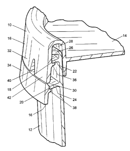
Referring firstly to Figure 1, a preferred embodiment of a container lid
according to the present invention is generally located by reference numeral
10. Lid 10 is shown mounted on a container 12, but container 12 is not
considered to be part of the present invention per se. Lid 10 includes a
planar central portion 14 and a peripheral annular skirt 16. The size of
container 12 is such that it holds typically from about 4 to 20 litres, and
container 12 and lid 14 are most commonly made from plastic, such as
polyethylene or polypropylene. However, any plastic or other material can
be used for lid 10 that has some resiliency, as will be described further
below.
Referring next to Figures 2 and 3, container 12 is shown having an
upper, peripheral, annular, outwardly disposed locking flange 18 and a lower,
annular, outwardly disposed locking flange 20 spaced from or below locking
flange 18. Locking flanges 18, 20 have respective undersides 22, 24 for
locking engagement with lid 10, as described further below. Container 12
also has a further peripheral annular flange 26 which forms the rim or brim
of container 12, and which is located in an annular sealing groove 28 in lid
2 0 10 located between the lid central portion 14 and the peripheral annular
skirt
16. When lid 10 is located on container 12, the container annular flange 26 is
wedged into lid sealing groove 28 to provide a good seal between the
container and the lid. In other words, sealing groove 28 sealingly engages
the rim 26 of the container.
As seen best in Figure 3, the lid annular skirt 16 overlies the container
locking flanges 18, 20. Annular skirt 16 defines or has an annular groove 30
which divides skirt 16 into a skirt upper portion 32 located adjacent to the
container upper locking flange 18, and a lower tear-off strip portion 34
3 0 located adjacent to the container lower locking flange 20. Annular groove
30
CA 02392054 2002-05-17
WO 01/40070 PCT/CA00/01406
_ 5 _
can be on the inside surface of annular skirt 16 or the outside surface of
this
skirt, or partially in both.
As seen best in Figures 3 and 4 to 6, the skirt upper portion 32 is
formed with inwardly disposed intermittent locking flange segments 36
which are adapted to engage the underside 22 of the container upper locking
flange 18. Similarly, the tear-off strip portion 34 defines or has an inwardly
disposed locking flange 38 which is adapted to engage the underside 24 of
the container lower locking flange 20.
As seen best in Figure 4, skirt upper portion 32 is formed with
triangularly shaped openings or windows 40 therein on either side of the
locking flange segments 36. Windows 40 border on the annular groove 30,
so that upon removal of tear-off strip portion 34, as will be described below,
windows 40 turn into downwardly disposed recesses or notches on either side
of the locking flange segments 36. The part of skirt or upper portion 32
located between windows 40 that contains locking flange segments 36 thus
becomes a flap 42 that can be pried outwardly and upwardly to release the
locking flange segments 36 from container upper locking flange 18 and thus
2 0 allow for the easy removal of lid 10 from container 12.
If desired, skirt upper portion 32 can be formed with a thin wall or
membrane (not shown) as part of windows 40. Such membranes, which
typically would be about .2 to .5 mm (0.008 to 0.020 inches) thick, would
2 5 prevent dirt or other foreign matter from entering windows 40 and
collecting
on flange 20. Such membranes would be easily broken upon flaps 42 being
pried upwardly to remove lid 10 from container 12.
As seen best in Figure 4, tear-off strip portion 34 is formed with a
3 0 window 44 located adjacent to annular groove 30. Again, window 44 could
CA 02392054 2002-05-17
WO 01/40070 PCT/CA00/01406
- 6 -
have a thin wall or membrane covering to keep dirt out, or it could be an
actual opening formed in tear-off strip portion 34. Tear-off strip portion 34
has a lower peripheral edge 46, and tear-off strip portion 34 is formed with a
reduced thickness portion 48 located between window 44 and lower
peripheral edge 46. To remove tear-off strip portion 34, one can insert a
tool,
such a screwdriver into window 44 and pry the tear-off strip portion 34
outwardly to break reduced thickness portion 48. This provides a flap or tab
50 that can be grasped and pulled outwardly to tear the tear-off strip portion
34 along groove 30 to remove tear-off strip portion 34. It will be appreciated
that removal of tear-off strip 34 also removes the locking flange or flanges
38, leaving only the intermittent locking flange segments 36 to engage the
container. This permits lid 10 to be removed easily by prying up flaps 42, yet
the intermittent locking flange segment 36 permit lid 10 to be placed again
on container 12 with good sealing engagement between the container rim or
annular flange 26 and lid sealing groove 28. It will also be appreciated that
breaking reduced thickness portion 48, and perhaps window 44. is a tamper
evidence feature for lid 10.
Refernng again to Figure 5, it will be seen that in this embodiment, lid
2 0 10 is provided with 4 equi-spaced intermittent locking flange segments 36
on
the skirt upper portion 32. Also, tear-off strip portion 34 has an inwardly
disposed locking flange 3 8 that is a continuous annular flange located around
the inside of tear-off strip portion 34. Locking flange 38 passes over the
reduced thickness portion 48, and depending on the thickness of locking
flange 38, it may be necessary to insert a knife into window 44 and cut
downwardly through locking flange 38 and reduced thickness portion 48 in
order to break out tab 50 in this embodiment.
In the embodiment shown in Figure 6, there are only two
3 0 diametrically opposed locking flange segments 36 on the inside of skirt
upper
CA 02392054 2002-05-17
WO 01/40070 PCT/CA00/01406
portion 32. Also, tear-off strip portion 34 has a pair of semi-circular and
inwardly disposed locking flanges or flange segments 3 8 rather than a
continuous locking flange 38. The Figure 6 embodiment is useful for smaller
containers where the lids need not be held so securely on containers 12. The
Figure 5 embodiment is useful for larger containers where stronger retention
between the lid and the container is desired. In fact, locking flange segments
36 could be located between all of the pairs of openings 40 to make an even
stronger connection between the lid and the container. It will be appreciated
that the size and the length and the number of locking flanges 36 and 38 can
be configured as desired to give the necessary shipping strength to the
container and lid combination of the present invention, or to provide for
easier or more difficult removal and reinstallation of lid 10 for the re-use
of
container 12.
As will be apparent to those skilled in the art in the light of the
foregoing disclosure, many alterations and modifications are possible in the
practice of this invention without departing from the spirit or scope thereof.
Accordingly, the scope of the invention is to be construed in accordance with
the substance defined by the following claims.