Note: Descriptions are shown in the official language in which they were submitted.
CA 02392179 2002-05-17
1
DESCRIPTION
ELECTRIC DEVICE AND ELECTRIC DEVICE SYSTEM
TECHNICAL FIELD
The present invention relates to an electric device being a small
electric mobile unit such as an electric scooter, an electric bicycle, an
electric
wheelchair, an electric cart, an electric walker for an aged person, or the
like,
which uses a relatively large secondary battery as a power source, and to an
electric device system in which the electric device is connected with a
portable device (a portable-type information processing device) such as a
notebook personal computer or the like and supplies electric power thereto
and the portable device is made usable as a display means or an inputting
means.
BACKGROUND TECHNOLOGY
Conventionally, there is an electric vehicle including a storage battery
pack composed of a plurality of storage batteries mounted as a power source
such as an electric bicycle or an electric wheel chair. Among electric
vehicles of this type, some run only by a driving force of a motor which is
driven by electric energy (electric power) from the mounted storage battery
pack, some run by a resultant force of a driving force of a motor and human
power, some switch and use a driving force of a gasoline engine and a driving
force of a motor, and the like.
There is a need of using portable devices such as a palmtop personal
computer, a notebook personal computer and the like in these conventional
small electric vehicles. In the. status quo, however, when these small
electric
CA 02392179 2002-05-17
2
vehicles are moving, it is impossible to use these portable devices in
operation
of the electric vehicles and thus the portable devices are only a burden.
Further, the aforementioned portable devices are operated by a battery, and
therefore there is a demand that the battery always be kept in a state of
being
fully charged or nearly fully charged to eliminate occurrence of a problem of
battery exhaustion during their use:
Furthermore, these portable devices have display ability capable of
sufficiently displaying a speedometer, a tachometer, a fuel gauge, an
odometer (an integrating traveling distance meter), a tripmeter (an
integrating
traveling distance meter with a reset function), and so on, necessary in an
instrument panel of the electric vehicle.
In a conventional four-wheeled vehicle such as a gasoline-powered
vehicle, a vehicle driven by combination of gasoline and a battery, an
electric
vehicle, or the like, the vehicle has a power supply such as a rather large
battery or power generator for the performance of the vehicle, or a large
number of electronic devices already exist in a car. Therefore, the power
supply is taken outside as a power source for the aforesaid portable devices,
which has facilitated the supply of electric power to the portable devices.
On the other hand, in the case of a small two-wheeled vehicle such as
a scooter, not many vehicles have a device called an electronic device
attended therein in the status quo, in which some vehicles have a very small
battery as a power source or some do not even have such a battery. Further,
the small battery itself has great noise from a power generator coupled to a
small engine and large variation in voltage, and thus it is a less-than-stable
power source.
Moreover, even in a small electric vehicle such as an electric bicycle,
an electric wheelchair, an electric cart, an electric walker. for an aged
person,
CA 02392179 2002-05-17
3
or the like, having thereon a relatively large battery and being capable of
supplying a relatively stable power supply, there is no vehicle that supplies
a
power supply to the outside. The portable devices carried by the small
electric vehicles during movement become only a burden as general baggage,
and the vehicles can not prepare (charge or the like) for their use.
It is an object of the present invention to improve the aforementioned
conventional disadvantage in the small electric device, more specifically to
make it possible to supply power to a portable device, particularly to a
portable information processing device including an input means and a
display means so as to effectively use display/input functions thereof, and
thereby, by the use of an ID or a password from the portable device connected
thereto, to improve the prevention of unauthorized use and theft of the
electric
device.
DISCLOSURE OF THE INVENTION
In order to attain the above objects, the present invention provides an
. electric device and an electric device system configured as follows:
An electric device according to the invention has a power supply
' including a rechargeable secondary battery, an electric motor operated by
electric power supplied from the power supply, a driver for driving the
electric motor, and a controller for monitoring, managing, and controlling the
driver and the whole device.
The electric device is characterized by comprising: a portable device
power supply to which a portable device is connectable and which supplies
electric power to the connected portable device; a second switch turned on
when a key is inserted into a key hole and turned to a first key position or .
further turned to a second key position; a first switch turned ~on only when
the
CA 02392179 2002-05-17
4
key is turned to the second key position (ON2); and a key switch interlocking
with a lock mechanism for an operating system including a steering wheel and
the like, the key of which can be pulled out in a predetermined turning range
including the first key position (ON 1 ), wherein the first switch (SW 1 ) is
interposed in a main power line for supplying electric power from the power
supply to the controller and the driver, and the second switch (SW2) is
interposed in a power line for supplying electric power from the power supply
to the portable device power supply.
Further, an electric device system according to the invention is
constituted by an electric device having a power supply including a
rechargeable secondary battery, an electric motor operated by electric power
supplied from the power supply, a driver for driving the electric motor, a
controller for monitoring, managing, and controlling the driver and the whole
device, a portable device power supply to which a portable device is
connectable and which supplies to the connected portable device electric
power supplied from the power supply, and a portable device interface means
for communicating information with the connected portable device, and
a portable device connected to the portable device power supply,
which communicates information with the electric device via the portable
device interface means and comprises a display for displaying display
information communicated from the electric device.
Further, the electric device is provided with means for sending out to
the portable device display information obtained by combining operation
authorization information and information required to be displayed on the
portable device after authorizing operation of the electric device, then
verifying a password when receiving the password from the portable device,
continuing to send out the display information if the password is correct,
CA 02392179 2002-05-17
4/1
continuing to send out the display information until number of errors reaches
a predetermined number if the password is incorrect, and prohibiting
operation of the electric device when the -number of errors reaches the
predetermined number, and
the portable device is provided with means for checking display
information when receiving the display information from the electric device,
processing the display information and displaying it after sending out a
predetermined password to the electric device if the display information is
correct, waiting for reception of next display information after sending out
the
password to the electric device until number of reception of abnormal display
data reaches a predetermined number if the display information in incorrect,
and sending out an abnormal data instead of the password to the electric
device after rewriting the abnormal data over the password and displaying an
abnormality when the number of reception of abnormal display data reaches
the predetermined number.
In such an electric device systam, it is preferable that the portable
device is provided with means for sending out ID data of a program operating
therein to the electric device, and the electric device is provided with means
for determining authorization/prohibition of operation of the electric device
based on the ID data received from the portable device.
Further, it is also preferable that the portable device is provided with
means for sending out an inputted password to the electric device, and the
electric device is provided with means for determining
authorization/prohibition of operation of the electric device based on the
CA 02392179 2002-05-17
password received from the portable device.
Furthermore, it is more preferable that the portable device is provided
with means for sending out ID data of a program operating therein to the
electric device and means for sending out an inputted password to the electric
device, and the electric device is provided with means for determining
authorization/prohibition of operation of the electric device based on the ID
data and the password received from the portable device.
It is also possible that, in the electric device system, the electric device
is provided with a switch for controlling a supply of electric power from the
power supply to the portable device power supply, and means for enabling
electric power supply from the portable device power supply by turning on
the switch when at least one of the ID data and the password received from
the portable device matches a previously registered ID data or password.
It is also possible that, in these electric device systems, the portable
device is provided with means for sending out inputted operation mode
specification information to the electric device, and the electric device is
provided with means for controlling the operation of the electric device
and/or
operation of the portable device power supply in accordance with the
operation mode specification information from the portable device.
It is desirable that the power supply in these electric devices or electric
Y
device systems is a power supply comprising a rechargeable battery unit
constituted by paring a storage battery pack being the secondary battery and a
memory for storing at least information on charge and discharge states of the
storage battery pack.
BRIEF DESCRIPTION OF DRAWINGS
FIG. 1 is a block diagram showing a configuration of a first
CA 02392179 2002-05-17
6
Y
embodiment of an electric device according to the invention;
FIG. 2 is a block diagram showing a configuration of a second
embodiment of an electric device according to the invention;
FIG. 3 is a block diagram showing an example of a portable device I/F
signal line in FIG. 2;
FIG. 4 is a block diagram showing another example of the portable
device I/F signal line in FIG. 2;
FIG. 5 is a flowchart showing operations of the electric device and a
portable device shown in FIG. 2;
FIG. 6 is a block diagram showing a configuration of a third
embodiment of an electric device according to the invention;
FIG. 7 is a flowchart showing operations of the electric device and a
portable device shown in FIG. 6;
FIG. 8 is a block diagram showing a configuration of a fourth
embodiment of an electric device according to the invention;
FIG. 9 is a flowchart showing operations of the electric device and a
portable device shown in FIG. 8;
FIG. 10 is a flowchart showing processing on specification of
authorization/prohibition of operation of the electric device and operation
mode specification of operation/non-operation of a portable device power
supply 7 by operation from the portable device after the state in which the
operation of the electric device is authorized, in the second to fourth
embodiments of the electric device according to the invention; and
FIG. 11 is a block circuit diagram showing a configuration example of
a power supply used in each embodiment of the electric device according to
the invention.
CA 02392179 2002-05-17
7
BEST MODE FOR CARRYING OUT THE INVENTION
Hereinafter, concrete embodiments of the invention will be described
with reference to the drawings.
FIG. 1 is a block diagram showing a configuration of a first
embodiment of an electric device according to the invention, in which a
secondary battery such as a storage battery pack or the like is employed as a
power supply to enable a supply of sufficient power to a portable device, and
a display section of the portable device is made usable also as a display
means
of the electric device.
An electric device 1 is constituted by a configuration mainly including
a power supply 2, a controller 3 for controlling each section of the electric
device l, a driver 4, an electric motor 5, a key switch 6, a portable device
power supply 7, a portable device power line 8, an instrument panel 9, and so
on.
The key switch 6 interlocks with a first switch SW1 and a second
switch SW2 at two stages which are switched by inserting a key into a key
hole and turning it, and a lock mechanism for an operating system including a
steering wheel and the like which operates at a position where the key can be
pulled out (a turning range with hatching in FIG. 1 ).
' 20 The power supply 2 is constituted by a rechargeable secondary battery
such as a lead storage battery, a Ni-Cd storage battery, a Ni-MH storage
' battery, a lithium ion storage battery, or the like, and supplies electric
power
necessary for operating the electric device.
The first switch SW1 interlocks with the key switch 6 provided in the
electric device 1 and turns on when the key switch 6 is operated to a second
key position (ON2) to supply electric power of the power supply 2 to each .
section via a main power line 1.2. - ,
CA 02392179 2002-05-17
8
The controller 3 starts control of each section of the electric device 1
when the first switch SW1 turns on and power is supplied thereto via the main
power line 12. When an instruction for operation is given by a user,
although not shown in the drawing, the controller 3 cooperates with the driver
4 via a driver control signal line 14 to cause the electric motor 5 to
operate,
thereby operating the electric device 1.
Further, the controller 3 monitors states necessary as the electric
.. device 1 such as a residual capacity of the secondary battery of the power
supply 2, the state of the power supply 2 such as temperature and so on if
necessary, the operating state of the electric motor 5, and so on, via a power
supply control signal line 13, the driver control signal line 14, and the
like;
and displays information on the instrument panel 9 via an instrument panel
I/F signal line 15, gives an alarm, and so on, in order to communicate
necessary information to the user. Accordingly, the controller 3 monitors,
manages, and controls the whole electric device 1.
The driver 4 receives the instruction from the controller 3 via the
driver control signal line 14 to operate the electric device 1 and
communicates
information required by the controller 3 such as the number of rotation of the
electric motor 5 or not shown wheels of the electric device 1, the temperature
of the electric motor 5, and the like, via the driver control signal line 14.
1'he electric motor 5 is a power source driven by the driver 4 to rotate
the wheels so as to cause the electric device 1 to run.
The portable device power supply 7 receives a supply of electric
power from the power supply 2 when the key switch 6 is operated to a first
key position (ON1) or the second key position (ON2) to turn on the second
switch SW2, and supplies electric power necessary for a portable device 10 ,
via the portable device power line 8. ---._.
CA 02392179 2002-05-17
9
The type of electric power supplied shall be a type required by the
portable device 10, for example, direct current electric power by a DC/DC
converter, or electric power of a commercial power supply by a DC/AC
inverter (AC100 V in Japan).
A power outlet of the portable device power supply 7 is desirably
pr ovided in a helmet case that does not require a special device for holding
the portable device 10.
Next, operations in the first embodiment are explained.
The key switch 6 can be removed in a range of a LOCK position
shown with hatching in FIG. 1. In this event, the operation of the electric
device 1 is in a stop state, where all the operating system including the
steering wheel and the like is locked. However, when the key is pulled out
at the first key position ON1 within the LOCK position, the second switch
SW2 turns on while the electric device 1 is kept locked to allow electric
power to be supplied to the portable device power supply 7, which makes it
possible to supply electric power to the portable device 10.
As described above, the provision of the first key position ON1 of the
key switch 6 within the range of the LOCK position enables the key to be
pulled out at the first key position ON 1, which makes it impossible for the
electric device 1 to operate. This makes it possible to prevent theft as well
as to maintain the supply of electric power to the portable device 10 to
enable
use of the portable device 10 such as a notebook personal computer or the like
even in that state.
By inserting the key into the key switch 6 and turning it to the second
key position ON2, the lock of the operating system including the steering
wheel and the like is released, and the first switch SW1 turns on. This
allows electric power to be supplied from the power supply:.2 to the
controller
CA 02392179 2002-05-17
3 and the driver 4 via the main power line 12 to bring the electric device 1
into a state capable of operating, and the electric power is also supplied to
the
portable device power supply 7 to maintain the supply of electric power to the
portable device 10.
The controller 3 supplied with electric power starts control of the
operation of the electric device 1 and cooperates with the driver 4 to operate
the electric motor 5 when an instruction for operation is given by the user,
although not shown in the drawing, thereby causing the electric device 1 to
run.
10 Moreover, the controller 3 monitors states necessary as the electric
device 1, that is, monitors a residual capacity of the secondary battery of
the
power supply 2, the state of the power supply 2 such as temperature and so on
if necessary, via the power supply control signal line 13, also monitors the
operating state of the electric motor 5 via the driver control signal line 14,
and
so on; and performs a display for communicating to the user information
necessary for the user on the instrument panel 9 via the instrument panel I/F
signal line 15, gives an alarm, and so on. Thus, the controller 3 has a
function of monitoring, managing, and controlling the whole electric device 1.
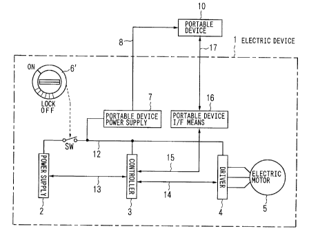
Next, a second embodiment of an electric device according to the
invention is explained with FIG. 2 to FIG. 5. FIG. 2 is a block diagram
showing a configuration of the second embodiment of the electric device, in
which the same sections as those in FIG. 1 are assigned the same numerals
and symbols.
The second embodiment differs from the first embodiment in that as
for a key switch 6', while the key switch 6 in the first embodiment is a two-
stage switch which turns on the second switch SW2 at the first key position
ON1 and turns on both of the first switch SW1 and second,~~witch SW2 at the
CA 02392179 2002-05-17
11
second key position SW2, the key switch 6' in the second embodiment only
turns on a switch SW at an ON position and turns off the switch SW at an
' OFF (LOCK) position to activate a lock mechanism of an operating system.
Therefore, there is no switch corresponding to the second switch SW2 shown
in FIG. 1.
In place of the instrument panel 9 shown in FIG. 1, a portable device
interface means (hereinafter, abbreviated to a "portable device I/F means") 16
and a portable device I/F signal line 17 are provided. The other
configuration is common with the electric device of the first embodiment
shown in FIG. 1, and thus the description thereof is omitted.
Therefore, operations of a power supply 2, a controller 3, a driver 4,
an electric motor 5, and the like are the same as those explained in the first
embodiment, and thus the description thereof is omitted here. Only
operations of sections differing from those of the first embodiment are
explained.
The switch SW turns on when the key switch 6' provided in the
electric device 1 is turned to the ON position by the key inserted into the
key
hole to allow electric power of the power supply 2 to be supplied to each
section via a main power line 12.
The fact that the key switch 6' being only in ON-OFF (LOCK) state is
used here in stead of using the key switch 6 having functions of the first
switch SW1 and the second switch SW2 as in the first embodiment does not
have a serious meaning but means that the object of the invention can be
attained even with a simple one-stage key switch. Accordingly, a two-stage
key switch may be used, when necessary, as in the first embodiment.
A portable device power supply 7 receives a supply of electric power
from the power supply 2 when the switch SW is turned~on~by the key switch
CA 02392179 2002-05-17
12
6' to supply electric power required by a portable device 10 via a portable
device power line 8. The type of electric power supplied shall be direct
current electric power or electric power of the commercial power required by
the portable device 10.
The portable device I/F means 16 receives information required by a
user from the controller 3 via the instrument panel I/F signal line 15,
converts
it into a signal appropriate for the portable device 10, and sends it out to
the
portable device 10 via the portable device I/F signal line 17. When the
portable device 10 such as a notebook personal computer or the like
connected to the portable device power line 8 receives the signal from the
portable device I/F signal line 17, the portable device 10 displays it on its
own
display section (a liquid crystal display or the like).
Further, when the portable device I/F means 16 receives via the
portable device I/F signal line 17 information from the portable device 10,
for
example, password information for authorization to operate the electric device
1, the portable device I/F means 16 communicates it to the controller 3 via
the
instrument panel I/F signal line 15.
It should be noted that, instead of independently providing the
portable device I/F means 16 as in this embodiment, its function may be given
to the controller 3.
Further, as the scheme of the portable device I/F signal line 17, a
serial I/F (interface) shown in FIG. 3 which is typically installed in a
palmtop
personal computer, a notebook personal computer, and the like, or an IrDA of
infrared data communication as shown in FIG. 4 is employed, which allows
the portable device I/F signal line 17 to provide for many types of devices.
It is necessary to add to the portable device 10 control software to
realize a display of information and an alarm sent froixa, the controller 3
CA 02392179 2002-05-17
13
through communication with the portable device I/F means 16 and to send out
necessary information such as a password and the like to the controller 3.
Next, specific operations in the case where the portable device is
connected to the electric device of the second embodiment to input a
password thereto are explained with a flowchart in FIG. 5. In FIG. 5, a flow
of the operation of the electric device 1 in this case is shown on the left-
hand
side, a flow of the operation of the portable device 10 is shown on the right-
hand side, and fold lines with arrows show mutual relationship therebetween.
' In this embodiment, the switch SW is turned on by the key switch 6 of
the electric device 1 to allow electric power of the power supply 2 to be
supplied via the main power line 12 to each necessary section of the electric
device 1, which enables operation thereof.
FIG. 5 shows a flowchart of the electric device 1 from the power
thereof being turned on by the key switch until it becomes a state capable of
operating, and communication of the electric device with the portable device
10 in operation.
In the electric device 1, the controller 3 sends out an ID request
command to the portable device via the instrument panel OF signal line 15,
the portable device I/F means 16, and the portable device I/F signal line 17
in
step A1, and waits for a response from the portable device 10 in step A2.
The ID is not an ID of the portable device 10 itself but shall be an ID
of a program operating in the portable device 10, which eliminates limitation
of portable devices.
The portable device 10 is waiting for the ID request command from
the electric device 1 in step B 1, and when the portable device 10 receives
the
ID request command from the electric device 1, it proceeds to step B2 and
sends out ID data to the electric device in response to the request.
CA 02392179 2002-05-17
14
Then, the electric device 1, in step A2, receives the ID data sent out
from the portable device 10 and verifies whether or not it is a correct ID
which is registered in advance, returns to step A1 when it is different from
the
ID, and proceeds to step A3 when it is correct.
In step A3, the electric device 1 sends out a password request
command for making a request to the user for a password for authorizing
operation of the electric device 1 via the portable device 10, and waits for
the
password in step A4.
The portable device 10 returns to step B2 and sends out the ID data
until the password request command is sent in step B3, and when the portable
device 10 receives the password request command in step B3, it proceeds to
step B4.
In step B4, the portable device 10 performs a display of requesting the
user to input a password, and waits for input of a password in step B5. Any
method may be employed for display contents and inputting a password if it is
suitable for properties of the portable device.
The portable device 10 returns to step B4 and maintains the display of
requesting input of a password until input of a password is finished in step
B5,
and proceeds to step B6 when the input of the password is finished.
In step B6, the portable device 10 stores the inputted password in a
predetermined location by a predetermined method and sends out the
password to the electric device.
The electric device 1 waits for the password being sent in step A4, and
when receiving the password from the portable device 10, the electric device
1 compares it with the previously registered password, proceeds to step A5
when they match, and returns to step A3 when they do not match.
In step A5, the controller 3 authorizes the operation of the electric
CA 02392179 2002-05-17
device 1 by a predetermined method, and the electric device 1 proceeds to
step A6.
In step A6, the electric device 1 sends out to the portable device 10
display information obtained by combining operation authorization
information and information required to be displayed on the portable device
as the electric device, and proceeds to step A7. To this display information,
parity and/or a checksum or the like are/is added to provide for
discrimination
of the information between correct and incorrect.
The portable device 10 checks the display information received from
10 the electric device 1 in step B7; proceeds to step B8 when it is correct,
and
proceeds to step B 11 when it is incorrect.
In step B8, the portable device 10 sends out a predetermined password
to the electric device 1, and proceeds to step B9.
On the other hand, the electric device 1 is waiting for the password as
15 a response to sending of the display information, in step A7. When
receiving the password from the portable device 10, the electric device 1
verifies the password and returns to step A6 when it is correct, and the state
of
the electric device 1 authorized to operate is maintained. When the
4
password is incorrect, the electric device 1 proceeds to step A8.
In step A8, the electric device 1 checks a series of errors of passwords,
and proceeds to step A9 when the number of errors reaches a predetermined
number. When the number of errors does not reach the predetermined
number, the electric device 1 returns to step A6.
In step A9, the controller 3 brings the electric device 1 into a state of
being prohibited to operate, and the electric device 1 returns to step A6. In
this event, the display information sent out in step A6 changes from operation
authorization to operation prohibition. It is conceivable that there are other
CA 02392179 2002-05-17
16
elements to prohibit operation of the electric device, but the description
thereof is not made because the elements are inherent in electric devices and
. can not be defined and they are not directly related to the invention.
The portable device 10 proceeds to step B 10 when the information
received in step B9 is correct, and returns to step B7 when it is incorrect to
maintain the preceding display.
In step B 10, the portable device 10 processes the display information
and displays it, and returns to step B7. When proceeding from step B7 to
step B11, the portable device 10 manages incorrect display information there,
proceeds to step B 12 when a predetermined number of abnormalities
continues, and returns to step B8 when the number of abnormalities does not
reach the predetermined number.
In step B 12, the portable device 10 rewrites abnormal data (data
differing from the password) over the password stored in the predetermined
location, and proceeds step B 13. The portable device 10 displays the
abnormality, and thereafter returns to step B8 and sends out the password.
Thereby, since an incorrect password is sent out to the electric device 1, the
abnormality occurnng in the display system is also detected on the electric
device 1 side, so that the electric device 1 is brought into a state of being
prohibited to operate.
The reason why the abnormality is displayed in step B 13 is to report
the abnormality to the user. Further, if the portable device 10 is provided
with a function of generating a sound, it may generate an alarm. It is also
preferable that when the portable device 10 receives operation prohibition
information from the electric device 1, it may similarly generate an alarm.
As a result, in addition to the key switch 6, connection of the portable
device 10 to the electric device 1 becomes a second key, and further the
CA 02392179 2002-05-17
17
password becomes a third key, which makes it possible to improve the
prevention of unauthorized use and theft.
While the operation of the electric device 1 is authorized by the
password in the above-described example, it is possible to conduct a control
only by the ID data without using the password.
In this case, the operation can be realized by omitting steps A3 and A4
on the electric device 1 side and steps B3, B4, BS and B6 on the portable
device 10 side and replacing "password" with "ID data" in other steps in the
flowchart shown in FIG. 5.
In this case, while there is no provision for the password being the
aforementioned third key, double protection against unauthorized use or the
like can be attained.
Conversely, it is possible to conduct a control only by the password
without using the ID. In this case, steps A1 and A2 on the electric device 1
side and steps B 1 and B2 on the portable device 10 side in the flowchart
shown in FIG. 5 should be omitted.
Further, even when the portable device 10 can not operate because of
lack of battery capacity, it is possible to hold the system as well as to
charge
the battery of the portable device 10 by supplying electric power from the
portable device power supply 7 to the portable device 10 via the portable
device power line 8.
Next, a third embodiment of an electric device according to the
invention is explained with reference to FIG. 6 and FIG. 7.
FIG. 6 is a block diagram showing a configuration of the electric
device, in which the same sections as those in FIG. 1 and FIG. 2 are assigned
the same numerals and symbols. .r
An electric device 1 of. the third embodiment differs from that of the
CA 02392179 2002-05-17
18
second embodiment shown in FIG. 2 only in that a switch SW3, which is
ON/OFF controlled by a switch control signal S3 from a controller 3, is
provided between a main power line 12 extending from a power supply 2 via
a switch SW and a portable device power supply 7.
The switch SW is first turned on by operating a key switch 6' to allow
electric power of the power supply 2 to be supplied to necessary sections of
the electric device 1 via the main power line 12, which makes the electric
device 1 capable of operating.
The switch SW3 is controlled by the switch control signal S3 from the
controller 3 and turns on to allow electric power from the power supply 2 to
be supplied to the portable device power supply 7.
When the switch SW turns on and electric power is supplied from the
power supply 2, the controller 3 starts control of operation of the electric
device 1. Further, the controller 3 has, in addition to the same function as
that of the controller 3 of the second embodiment, a function of controlling
opening/closing of the switch SW3 by the switch control signal S3 to control
the supply of electric power to the portable device power supply 7.
Next, operation of the electric device of the third embodiment when a
portable device is connected thereto is explained with FIG. 7.
FIG. 7 shows a flowchart of the electric device from the power thereof
being turned on by the key switch until it becomes a state capable of
operating,
and communication of the electric device with the portable device in
operation. It should be noted that steps B 1 to B 13 of the operation of the
portable device on the right-hand side are the same as steps B 1 to B 13 of
the
operation of the portable device in the flowchart shown in FIG. 5, and thus
the
description thereof is omitted. _
The electric device 1 starts operation when the switch SW turns on by
CA 02392179 2002-05-17
19
operating the key switch 6' and electric power is supplied to the controller
3.
Then, in step C1, the electric device 1 first turns on the switch SW3 by
the switch control signal to cause the portable device power supply 7 to
operate for the case of a battery of a portable device 10 being uncharged, and
proceeds to step C2.
In step C2, the electric device 1 sets a portable device power supply
timer, and proceeds to step C3. The portable device power supply timer is a
timer for specifying a period of operation of the portable device power supply
to prevent power supply (charge) to the portable device 10 only by application
of power caused by the key switch 6' and to reduce unnecessary power
consumption.
In step C3, the controller 3 sends out an ID request command to the
portable device 10 via an instrument panel I/F signal line 15, a portable
device
I/F means 16, and a portable device I/F signal line 17, and waits for a
response from the portable device 10 in step C4.
Thereby, the portable device 10 sends out ID data in step B2, and
when receiving the ID data, the electric device 1 verifies whether or not it
is a
previously registered ID in step C4. The electric device 1 proceeds to step
C 12 when it is different from the registered ID, and proceeds to step CS when
it is correct.
In step C5, the electric device 1 sends out a password request
command for making a request to the user for a password for authorizing
operation of the electric device 1 via the portable device, and waits for
reception of the password in step C6.
When receiving the password from the portable device 10, the electric
device 1 compares it with a previously registered password in step C6. r
When they match, the electric device 1 determines that' tho. correct password
CA 02392179 2002-05-17
has been sent from the portable device and proceeds to step C7, and when
they do not match, it proceeds to step C 14.
In step C7, the controller 3 authorizes the operation of the electric
device 1 by a predetermined method, and the electric device 1 proceeds to
step C8.
In step C8, the electric device 1 sends out to the portable device
display information obtained by combining operation authorization
information and information required to be displayed on the portable device
as the electric device, and proceeds to step C9. To this display information,
10 pity ~~or a checksum or the like are/is added to provide for discrimination
of the information between correct and incorrect.
In step C9, the electric device 1 is waiting for a password from the
portable device 10 as a response to sending of the display information.
When receiving the password from the portable device 10, the electric device
15 1 determines whether or not it is the correct password and returns to step
C8
when it is correct, and the state of the electric device 1 authorized to
operate is
maintained. When the password is incorrect, the electric device 1 proceeds
to step C 10.
In step C 10, the electric device 1 checks a series of errors of
20 passwords, and proceeds to step C 11 when the number of errors reaches a
predetermined number. When the number of errors does not reach the
predetermined number, the electric device 1 returns to step C8.
In step C 11, the controller 3 brings the electric device 1 into a state of
being prohibited to operate, and the electric device 1 returns to step C8. In
this event, the display information sent out in step C8 changes from operation
authorization to operation prohibition.
Meanwhile, when proceeding from step C4 to step.~Cl2, the electric
CA 02392179 2002-05-17
21
device 1 checks the portable device power supply timer, proceeds to step C 13
when the specified period has elapsed, and returns to step C3 when the
specified period has not elapsed'.
In step C 13, the controller 3 turns off the switch SW3 by the switch
control signal S3 to stop the operation of the portable device I/F means 16,
and returns to step C3.
Also when proceeding from step C6 to step C 14, the electric device 1
checks the portable device power supply timer, proceeds to step C 15 when the
specified period has elapsed, and returns to step C5 when the specified period
has not elapsed.
In step C15, the controller 3 turns off the switch SW3 by the switch
control signal S3 to stop the operation of the portable device I/F means 16
and
returns to step C5.
Also in the third embodiment, it is possible to use only the ID or only
the password as in the second embodiment.
When only the ID is used, steps C5, C6, C 14 and C 15 on the electric
device 1 side and steps B3, B4, B5 and B6 on the portable device 10 side in
the flowchart of FIG. 7 should be omitted, and "password" should be replaced
with "ID data".
When only the password is used, steps C3, C4, C12 and C13 on the
electric device 1 side and steps B 1 and B2 on the portable device 10 side in
the flowchart of FIG. 7 should be omitted.
Next, a fourth embodiment of an electric device according to the
invention is explained with reference to FIG. 8 and FIG. 9.
FIG. 8 is a block diagram showing a configuration of the electric
device, in which the same sections as those in FIG. 1, FIG. 2 and FIG. 6 are
assigned the same numerals and symbols, and the description thereof is
CA 02392179 2002-05-17
22
omitted.
An electric device 1 of the fourth embodiment differs from that of the
second embodiment shown in FIG. 2 only in that the key switch 6' is not
provided and a switch SWa is interposed between a power supply 2 and a
main power line 12 and a switch SWb is interposed between the power supply
2 and a portable device power supply 7, respectively, such that the switch
SWa and the switch SWb are ON/OFF controlled by a switch control signal
Sa and a switch control signal Sb from a controller 3, respectively.
It should be noted that the controller 3 is supplied with electric power
at all times from the power supply 2 via a power supply control signal line
13,
and periodically operates the portable device power supply 7 by the switch
control signal Sb as well as verifies the presence or absence of connection of
a
portable device 10 using a portable device I/F means 16 via an instrument
panel I/F signal line 15. When receiving a correct ID from the portable
device 10, the controller 3 recognizes the connection of the portable device
10,
' and proceeds with processing for operation of the electric device 1.
When the controller 3 turns on the switch SWa by the switch control
4
signal Sa, electric power from the power supply 2 is supplied to a driver 4,
and when the controller 3 turns on the switch SWb by the switch control
signal Sb, electric power from the power supply 2 is supplied to the portable
device power supply 7.
Operations in the fourth embodiment are explained with a flowchart in
FIG. 9.
FIG. 9 shows the flowchart of the electric device from periodical
checks on connection of the portable device by the electric device until it
becomes a state capable of operating, and communication of the electric
device with the portable device in operation. . ...
CA 02392179 2002-05-17
23
It should be noted that steps CS to C 14 of the operation of the electric
device 1 on the left-hand side are the same as steps CS to C14 of the
operation
of the electric device in the flowchart shown in FIG. 7, and steps B 1 to B 13
of
' the operation of the portable device on the right-hand side are the same as
steps B 1 to B 13 of the operation of the portable device in the flowchart
shown
in FIG. 7, and thus the description thereof is omitted.
In step C21, the electric device 1 turns on the switch SWb by the
switch control signal Sb to cause the portable device power supply 7 to
operate for the case of a battery of the portable device 10 being uncharged,
and proceeds to step C22.
In step C22, the controller 3 sends out an ID request command to the
portable device 10 via the instrument panel I/F signal line 15, the portable
device I/F means 16, and a portable device I/F signal line 17, and waits for a
response from the portable device 10 in step C23.
When receiving ID data from the portable device 10, the electric
device 1 checks whether or not it is a correct ID matching a previously
registered ID in step C23. The electric device 1 proceeds to step C24 when
it is correct, and proceeds to step C25 when it is incorrect.
Then, the electric device 1 turns off the switch SWb in step C25,
thereafter waits only for a predetermined period in step C26, and returns to
step C21.
In step C24, the electric device 1 sets a portable device power supply
timer for specifying a period of operation of the portable device power supply
to prevent power supply (charge) to the portable device, and proceeds to step
C5.
While the operation thereafter is the same as that of the electric device
shown in FIG. 7, the switch SWb is turned off in step C15~.-~~
CA 02392179 2002-05-17
24
Also in the fourth embodiment, it is possible to use only the ID or
only the password as in the second embodiment.
When only the ID is used, steps C5, C6, C 14 and C 15 on the electric
device side and steps B3 to B6 on the portable device 10 side in the flowchart
of FIG. 9 should be omitted, and "password" should be replaced with "ID
data".
Alternatively, when only the password is used, steps C22, C23, C25
and C26 on the electric device side and steps B 1 and B2 on the portable
device 10 side in the flowchart of FIG. 9 should be omitted.
It should be noted that, in step C21 in FIG. 9, the switch SWb is
unconditionally turned on by the switch control signal Sb to cause the
portable device power supply 7 to operate for the case of the battery of the
portable device 10 being uncharged. However, it is also adoptable that only
when at least one or both of the ID data and the password received from the
portable device matches/match the previously registered ID data or/and
password, the switch SWb is turned on to cause the portable device power
supply 7 to operate so as to enable the supply of electric power to the
portable
device 10.
FIG. 10 shows a flow of specification of authorization/prohibition of
the operation of the electric device 1 and operation mode specification of
operation/non-operation of the portable device power supply 7 by operation
from the portable device 10 after the state in which the operation of the
electric device 1 is authorized.
This makes it possible to specify an operation in accordance with
user's will and to effectively utilize the electric power of the power supply
2.
Further, by using a password for authorization of the operation, it becomes
possible to prevent the operation mode from being changed-.:by persons except
CA 02392179 2002-05-17
an authorized user so as to prevent mischief, unauthorized use, theft, and the
like.
This can be realized by any of the above-described second to fourth
embodiments.
As a method for proceeding to the above operation, any method is
adoptable if it is suitable for properties of the portable device, such as
operation of a specific key, input of commands, or the like.
Processing in each step in FIG. 10 is explained here. First of all, a
display of specifying an operation mode is performed in accordance with
10 operation mode specification by a user in step M1, and the processing
proceeds to step M2.
In step M2, specified contents by the user are judged, and when it is
authorization of the electric device 1, the processing proceeds to step M3 and
otherwise the processing proceeds to step M6.
15 In step M3, whether or not the portable device power supply 7 is ON
is determined, and when it is OFF (non-operation), the processing proceeds to
step M5, and when it is ON (operation), the processing proceeds to step M4.
In step M4, authorization of operation of the electric device 1 and
operation of the portable device power supply 7 are specified, and the
20 processing proceeds to step M9. In step M5, authorization of operation of
the electric device 1 and non-operation of the portable device power supply 7
are specified, and the processing proceeds to step M9.
In step M6, whether or not the portable device power supply 7 is ON
is determined, and when it is ON (operation), the processing proceeds to step
25 M7, and when it is OFF (non-operation), the processing proceeds to step M8.
In step M7, prohibition of operation of the electric device 1 and operation of
the portable device power supply 7 are specified, and the. processing proceeds
CA 02392179 2002-05-17
26
to step M9. In step M8, prohibition of operation of the electric device 1 and
non-operation of the portable device power supply 7 are specified, and the
processing proceeds to step M9.
In step M9, whether or not the operation mode is ended is determined,
and when it is not ended, the processing returns to step M1 and when it is
ended, the processing is ended.
Some of the above-described embodiments are explained in examples
each using a secondary battery composed of a typical storage battery pack as
the power supply of the electric device in a small mobile unit. However, it is
preferable to use a rechargeable secondary battery constituted by paring a
secondary battery composed of a storage battery pack and a memory for
storing at least information about charge and discharge states of the storage
battery pack.
This makes it possible to supply power sufficiently to the portable
device connected to the portable device power supply and to manage the
power supply of the electric device, so as to utilize the power supply further
effectively.
FIG. 11 is a block circuit diagram showing a configuration example of
the power supply. The power supply 2 is constituted by battery units 21, 22
and 23, a controlling power supply 29, a controller 28, a charger unit 30
including a charger 27, and so on.
Storage battery packs 21B, 22B and 23B may include various types of
secondary batteries such as a nickel-cadmium battery and a nickel-metal
hydride battery. Further, each of memories 24, 25 and 26 is a nonvolatile
memory such as an EEPROM, a flash ROM, a RAM backed up by a battery
or the like, into which various kinds of information can be written which
includes at least the information about charge and discla~rge states of the
CA 02392179 2002-05-17
27
associated storage battery pack by the charger or the controller 28 provided
in
the power supply 2.
As for the battery units 21, 22 and 23, the charge and discharge states
of the storage battery packs 21B, 22B and 23B included therein can be
recognized precisely by referring to the information stored in the memories
24,
25 and 26 even when they are mounted on the electric device 1 or they are
detached therefrom to be in a single state, and thus appropriate charge and
discharge controls can be conducted all the time.
The power supply 2 of this embodiment has the plurality of battery
units 21, 22 and 23 and the common charger unit 30 for charging the
respective storage battery packs 21B, 22B and 23B, which are detachably
mounted on the electric device main body, respectively.
The battery units 21, 22 and 23, having the same structure, are units in
which the storage battery packs 21B, 22B and 23B are paired for integration
with the memories 24, 25 and 26 such as EEPROMs or the like. The battery
units 21, 22 and 23 and battery unit installation sections (not shown) of the
above-described power supply 2 provided in the electric device 1 are provided
respectively with connectors Bal, Ba2 and Ba3, connectors Bbl, Bb2 and
Bb3, and connectors Bcl, Bc2 and Bc3, each of which is composed of paired
terminals, as means for electrically connecting and disconnecting the battery
units 21, 22 and 23 to/from the main body side of the power supply 2 incident
to attachment and detachment of the battery units 21, 22 and 23, respectively.
The charger unit 30 is a unit containing therein the charger 27 having
a microcomputer and switches SW21, SW22 and SW23 corresponding to the
battery units 21, 22 and 23, and is provided with connectors Cpl, Cp2, Cp3,
Cgl, Cg2, Cg3, Csl, Cs2 and Cs3, each of which is composed of paired
terminals, between the charger unit 30 and the charger unit installation
CA 02392179 2002-05-17
28
r
sections (not shown) of the power supply 2, as connecting means for
electrically connecting and disconnecting the charger unit 30 to/from the main
body side of the power supply 2 incident to attachment and detachment of the
charger unit 30.
Further, the connectors Csl, Cs2 and Cs3 of the charger unit 30 and
the connectors Ba3, Bb3 and Bc3 of the battery units 21, 22 and 23 are
connected to each other respectively, that is, the connectors Csl and Ba3, the
connectors Cs2 and Bb3, and the connectors Cs3 and Bc3, by bus lines for
writing and reading to/from the memories 24, 25 and 26, and further
connected to the controller 28.
Furthermore, the power supply 2 is provided with, on the main body
side, the controller 28 for controlling the operation of the whole power
supply
2, the main power line 12 for supplying electric power to each section of the
electric device 1 via the controlling power supply 29 connected to the
controller 28 and the above=described switch SW and so on, and three
switches SW11, SW12 and SW13 interposed in discharge (feed) lines from
the battery units 21, 22 and 23 to the controller 28 and the main power line
12.
The charger 27 in the charger unit 30 has a function of charge
controlling the storage battery packs 21B, 22B and 23B of the battery units
21,
22 and 23, and a function of reading and writing information from/into the
memories 24, 25 and 26.
Further, the controller 28 similarly has therein a function of reading
and writing information from/into the memories 24, 25 and 26 of the battery
units 21, 22 and 23 in addition to a function of controlling the whole power
supply 2.
The charger 27 receives a supply of alternating-'current power from a
CA 02392179 2002-05-17
29
commercial power supply 100, rectifies and smoothes it to thereby make it
direct current, converting it to an output voltage suitable for charge.
Further,
the charger 27 reads and temporarily stores the information about the charge
and discharge states of the storage battery packs 21B, 22B and 23B from the
memories 24, 25 and 26 of the plurality of the mounted battery units 21, 22
and 23, and selectively turns on one of the switches SW21, SW22 and SW23
by a SW2n control signal to charge the storage battery pack of the battery
unit
selected based on the information. Thereby, the storage battery pack of the
battery unit connected via the switch turned on is charged.
FIG. 11 shows an example in which three battery units are mounted,
but the object of the invention can be achieved by mounting at least one
battery unit. In addition, the charger unit 30 is also detachably mounted on
the main body of the power supply 2, so that it can easily be detached from
the electric device 1 and used outside the electric device 1, but it may be
provided fixedly to the main body of the power supply 2 provided in the
electric device 1.
Each of the storage battery packs 21B, 22B and 23B of the battery
units 21, 22 and 23 is constituted by connecting in series a plurality of
rechargeable storage batteries or secondary batteries.
In each of the memories 24; 25 and 26 of the battery units 21, 22 and
23, information specific to a battery such as a rated capacity, temperature
characteristics, preservation characteristics and the like, and information
about the charge and discharge states of the battery such as an amount of
charge, an amount of discharge, the numbers of charges and discharges and
the like of each of the storage battery packs 21B, 22B and 23B, are stored.
As described above, the battery units 21, 22 and 23 have individual
information respectively, which allows the plurality of the battery units 21,
22
CA 02392179 2002-05-17
and 23 to be attached and detached in any order. The switches S W 11, S W 12
and SW13, which are provided along respective feed lines between the battery
units 21, 22 and 23, and, the controller 28 and the main power line 12, are
selectively turned on by an SWIn control signal outputted based on the
5 controlling function of the controller 28, thereby selecting which battery
unit
is used to feed power to the controller 28 and the main power line 12.
The controller 28, having a microcomputer therein, detects installation
states of the plurality of the battery units 21, 22 and 23 by the controlling
function in conjunction with the reading/writing function, reads and
10 temporarily stores the information stored in the memories 24, 25 and 26
therein, selects based on the information a battery unit to be discharged, and
controls its discharging current and discharging voltage, to thereby conduct
management appropriate for the battery characteristics of the battery unit
used
and the characteristics of the power supply 2 when necessary.
15 Further, it is also possible to display information on the mounted
battery units, for example, the battery residual capacity of the individual or
the total of the plurality of the mounted battery units, charge request when
there is a battery unit required to be charged and the like, or to give an
alarm
and the like, when necessary. In other words, this controller 28 has
20 functions of controlling ON/OFF states of the switches SW11, SW12 and
SW13 and managing and controlling the whole power supply, based on the
information stored in the memories 24,25 and 26 of the battery units 21, 22
and 23.
Further, the controller 28 is also coupled to the controller 3 for
25 controlling the whole electric device 1 shown in FIG. 1, FIG. 2, FIG. 6 and
FIG. 8 via the power supply control signal line 13, so as to exchange
information and a command.
CA 02392179 2002-05-17
31
The controlling power supply 29 has a function of supplying required
electric power to the controller 28 when at least one of the battery units 21,
22
and 23 is mounted on the power supply 2. The controlling power supply 29
is supplied with electric power also when at least one storage battery pack
among the battery units is charged by the charger 27, and in this event the
controlling power supply 29 operates when necessary to supply electric power
to the controller 28.
Further, when each of the battery units 21, 22 and 23 is detached or
when a command to stop the power supply 2 is given or the like, the
controlling power supply 29 supplies electric power to the controller 28 until
the controller 28 stops the supply of electric power to the main power line
12,
writes information about charge and discharge states and the like of the
storage battery packs of operating battery units among the battery units 21,
22
and 23 into the memories in the battery units, and stops the power supply 2 in
safety and the like to thereby complete necessary processing.
Thus, the electric power supplied from the power supply 2 via the
main power line 12 based on the controlling function of the controller 28 is
supplied to the controller 3 and the driver 4 via the switch SW1 by operation
of the key switch in the first embodiment shown in FIG. 1.
Further, as explained in the above-described first to fourth
embodiments, electric power is supplied to each section of the electric device
1 via the main power line 12 and also to the portable device power supply 7,
which makes it possible to supply electric power to the portable device 10
connected thereto.
The power supply 2 may comprise: a plurality of battery units
detachably mounted thereon, each battery unit constituted by integrating a
storage battery pack, a memory for storing at least information about charge
CA 02392179 2002-05-17
32
and discharge states of the storage battery pack, and a charger for charging
the
storage battery pack; connectors; provided on each battery unit and a battery
unit installation section on the device main body side, for performing
electrical connection/disconnection to/from the device main body side
incident to attachmentJdetachment of the battery unit; and a driver for
driving
a load and a controller for controlling a supply of electric power from each
battery unit to the driver by refernng to the information stored in the memory
of each mounted battery unit, which are provided on the device main body
side.
Alternatively, it is, of course, adoptable to fixedly provide each
battery unit and the charger unit constituting the power supply 2 to the main
body of the electric device 1.
INDUSTRIAL APPLICABILITY
As has been described, according to the invention, the provision of a
portable device power supply in an electric device enables supply (charge) of
electric power to a portable device even in a small electric device.
Further, the portable device connected via a portable device I/F signal
line can also be used as a display device of the electric device.
Furthermore, in addition to a key switch, an ID of the portable device
or its operation program is sent/received to/from the electric device, so as
to
Y
prevent unauthorized use and/or theft.
Additionally, by using an inputting function of the portable device, it
is also possible to improve safety through the use of a password.