Note: Descriptions are shown in the official language in which they were submitted.
CA 02392319 2002,05-22
` r .
DESCRIPTION
WATER ELECTROLYZING DEVICE
FIELD OF THE INVENTION
This invention relates to a water electrolysis device of a solid electrolyte
type.
BACKGROUND ART
Recently, a highly efficient water electrolysis by means of a solid polymer
electrolyte membrane has gained notice. FIG. 5 illustrates one example of the
water electrolysis device of the solid polymer electrolyte type among those
known
heretofore. In FIG. 5, electrochemical cell 41 includes a number of solid
polymer
electrolyte membrane units 42 connected in tandem, and electrode end plates
43,
43 disposed at opposite ends for current-carrying. The solid polymer
electrolyte
membrane units 42 include as main parts solid polymer electrolyte membrane 44,
porous electric current suppliers 45, 45 disposed on the opposite faces of the
solid
polymer electrolyte membrane 44, and bipolar electrode plates 46, 46 disposed
on
the outer sides of the porous electric current suppliers 45, 45. The solid
polymer
electrolyte membrane 44 is generally a polymer membrane made of a proton
conductive material. Where voltage is applied across the electrode end plates
43,
43, the one face of the bipolar electrode plates 46, 46 acts as cathode and
the
opposite one acts as anode. Taking into account one bipolar electrode plate
46,
that is a common component for adjacent solid polymer electrolyte membrane
units
42, 42.
FIG. 6 is a disassembled cross sectional view of one solid polymer
electrolyte membrane unit 42, in which the solid polymer electrolyte membrane
44
CA 02392319 2008-10-28
2
has opposite faces on which porous catalytic layers 47 are made of the
platinum
group metals. On the opposite sides of the solid polymer electrolyte membrane
44
are respectively formed spaces sealingly enclosed by the solid polymer
electrolyte
membrane 44, the bipolar electrode plates 46, 46 and annular gaskets 48, 48.
These spaces respectively act as cathode chamber A and anode chamber B
discussed later (those represented in chain double-dashed lines in FIG. 6).
The
cathode chamber A and the anode chamber B respectively accommodate the porous
electric current suppliers 45, 45. As the solid polymer electrolyte membrane,
it is
preferable to use a cation exchange membrane (e.g., fluorocarbon-type sulfonic
acid,
cation ion-exchange membrane, such as Nafion 117 and Nafion 115 from DuPont).
Now, the description wiIl be made for the operation of a conventional water
electrolysis device. As illustrated in FIG. 5, where an electric current is
sent
across the electrode end plates 43, 43 so as to enable the electrode plate of
the left
hand side in FIG. 5 to act as anode and the electrode plate 43 of the right
hand side
to act as cathode, each of the bipolar electrode plates 46, 46 has a left side
portion
acting as cathode of one unit 42 and right side portion acting as anode of
another
unit 42. That is, one bipolar electrode plate 46 acts as a component of
cathode-side
49 in the solid polymer electrolyte membrane unit 42 on the left hand. side of
the
bipolar electrode plate 46, while acting as a component of anode-side 50 in
the solid
polymer electrolyte membrane unit 42 on the right hand side of the bipolar
electrode plate 46. Thus, in each solid polymer electrolyte membrane unit 42,
the
cathode chamber A and the anode chamber B are respectively formed on the right
and left hand sides of the solid polymer electrolyte membrane 44.
Where demineralized water is fed into the anode chamber B via
demineralized-water feeding passage 51 (see FIG. 5) under the above state, the
reaction 2H2O-->O2+4H+4e- takes place in the anode chamber B, generating
oxygen gas. Protons generated in the anode chamber B move along with a small
* Trade-mark
I f
CA 02392319 2002-05-22
3
volume of water within the solid polymer electrolyte membrane 44, which has a
proton conductivity, and reach the cathode chamber A. The protons which have
reached the cathode chamber A cause the reaction 4H+ +4e----2H2i generating
hydrogen gas.
According to the hydrogen gas and oxygen gas generating process in the
water electrolysis device of solid polymer electrolyte type as summarized
above,
hydrogen and oxygen generated by the process are fed to use points, following,
for
example, a flow as illustrated in FIG. 7. That is, in FIG. 7, hydrogen gas
formed in
electrochemical cell 52 flows through line 53 to hydrogen separation tank 54,
where
water is separated therefrom, and is fed to the respective use points via
dehumidifier 55. On the other hand, oxygen gas formed in the electrochemical
cell
52 flows through the line 56 to oxygen separation tank 57, where water is
separated therefrom, and is released to the atmosphere.
Meanwhile, water electrolysis is carried out by sending a predetermined
electric current in a predetermined voltage, and therefore it is preferable to
increase energy efficiency (voltage efficiency x current efficiency) to reduce
electric
power consumption during the water electrolysis.
The current efficiency herein varies within the range of about 90-98%
independently of temperature. On the other hand, the voltage efficiency is
represented in theoretical working voltage/actual electrolysis voltage so that
it has
temperature dependency. That is, unless the electrolytic temperature is
maintained at relatively high levels, the actual electrolysis voltage is
increased,
resulting in lowered voltage efficiency. Along with the development of an
electrochemical cell with high performance, a maximum voltage efficiency,
which
was hitherto about 80%, can be improved to about 96%, provided that the
electrolysis temperature is maintained between 80- 120 C.
However, in the conventional water electrolysis device, it is necessary to
CA 02392319 2002-05-22
4
carry out the water electrolysis at a relatively low electrolytic temperature
of 45`O
for the reasons stated below. As a result, the energy efficiency was about
55%.
That is, demineralized water used for the water electrolysis is recycled in
light of costs or the like. In order to properly carry out the water
electrolysis while
preventing contamination of a solid polymer electrolyte membrane by keeping
the
purity of the demineralized water for the water electrolysis constant, ions
contained in the demineralized water must be removed. Generally, these ions
are
removed by using an ion exchange resin as an ion removing means. Since this
ion
exchange resin has a low heat resistance temperature (about 55 C), the
electrolysis
temperature was conventionally set at a relatively low temperature of about 45
c.
More specifically, in the conventional water electrolysis device, as shown in
Fig. 7, demineralized water with oxygen gas separated therefrom at the oxygen
separation tank 57 is fed into line 59 via line 65 and demineralized-water
circulation pump 69. With heat exchanger 60 interposed in the line 59,
demineralized water flowing in the line 59 is cooled to about 45`O by cooling
water
fed through line 61. Then, nonreproductive polisher 62 with an ion exchange
resin
interposed in the line 59 removes ions from the demineralized water to form a
highly demineralized water, which is fed into the electrochemical ce1152
through
filter 63 and line 64. In FIG. 7, the reference numerals 58 and 70
respectively
represent demineralized-water tank and demineralized-water make-up pump for
feeding demineralized make-up water to the oxygen separation tank 57 from the
demineralized-water tank 58.
On the other hand, the demineralized water with hydrogen gas separated
therefrom in the hydrogen separation tank 54 is introduced via line 66 into
gas
scrubber 67, in which hydrogen gas dissolved in the demineralized water is
released, and returned to the demineralized-water tank 58. The hydrogen gas
separated from the demineralized water in the hydrogen separation tank 54 is
, ,
CA 02392319 2002-05-22
dehumidified by the dehumidifier 55 and then fed to a use point. In order to
improve the efficiency in dehumidifying hydrogen gas at the dehumidifier 55,
cooling water fed through the line 61 is drawn into the dehumidifier 55 via
the line
68 in the water electrolysis device as illustrated in FIG. 7, thereby allowing
the
5 dehumidifier 55 to be kept at a lower temperature.
As described above, the conventional electrolysis device is designed only to
lower the temperature of demineralized circulating water (generally about 85-
120'C) or lower the temperature of moisture-containing hydrogen gas (generally
85-1209C), with no consideration of utilizing demineralized water discharged
from
the oxygen separation tank 57 or the hydrogen separation tank 54, as well as
the
thermal energy of moisture-containing hydrogen gas discharged from the
hydrogen
separation tank 54.
As described above, there is a demand in these years for improvement in
energy efficiency so as to reduce electric power consumption during the water
electrolysis. In order to meet this demand, it is necessary to maintain a high
temperature during the water electrolysis, thereby preventing lowering of the
voltage efficiency, which has a high temperature dependency. For example,
where
a maximum energy efficiency of 94% is to be secured by maintaining a voltage
efficiency of 96%, it is necessary to keep the electrolysis temperature in the
range
between about 80 and 120`O, as described above. On the contrary, the
conventional water electrolysis device could not carry out the water
electrolysis
under such a high temperature due to the heat resistant temperature of the ion
exchange resin (about 55t).
The present invention was conceived in light of the problems inherent in
the prior arts. It is an object of the present invention to provide a water
electrolysis cell that is capable of reducing ion concentration of
demineralized
water to be fed into an electrochemical cell without using an ion exchange
resin,
CA 02392319 2002-05-22
6
and maintaining a high electrolysis temperature.
SUMMARY OF THE INVENTION
In order to achieve the above object, there is provided a water electrolysis
device that is capable of reducing ion concentration of demineralized water
circulating in a demineralized water circulation line (hereinafter referred to
"demineralized circulating water") by discharging a part of demineralized
water
with its purity deteriorated (ion concentration increased) from the
circulation line
to the outside, as well as feeding a predetermined volume of highly
demineralized
make-up water to the demineralized water circulation line via a demineralized
water make-up line, and at the same time increasing the temperature of the
demineralized make-up water added to the demineralized circulating water and
hence holding the electrolysis temperature at high levels by heat exchanging
demineralized water of high temperature discharged to the outside with the
demineralized make-up water fed into the demineralized water circulation line.
According to one aspect of the present invention, there is provided a water
electrolysis device for generating hydrogen gas and oxygen gas by
electrolyzing
demineralized water in an electrochemical cell that includes: an oxygen
separation
tank for storing demineralized water to be fed to the electrochemical cell; a
demineralized water circulation line for feeding demineralized water from the
oxygen separation tank to the electrochemical cell and returning demineralized
water, which has been electrolyzed and remains in the electrochemical cell, to
the
oxygen separation tank; a demineralized water make-up line for feeding
demineralized make-up water to at least any one of the oxygen separation tank
and
the demineralized water circulation line; a first heat exchanger interposed in
the
CA 02392319 2002-05-22
7
demineralized water make-up line; and a first demineralized water discharge
line
having a proximal end communicated with at least any one of the oxygen
separation tank and the demineralized water circulation line, and a distal end
extending through the first heat exchanger to the outside, in which heat
transfer
between the demineralized make-up water fed through the demineralized water
make-up line and the demineralized water discharged to the outside through the
first demineralized water discharge line is carried out at the first heat
exchanger.
With the water electrolysis device having the above arrangement, a part of
demineralized water flowing in the demineralized water circulation line is
discharged through the first demineralized water discharge line, while highly
demineralized make-up water is fed into the demineralized water circulation
line
through the demineralized water make-up line, so that the ion concentration of
the
demineralized circulating water flowing in the demineralized water circulation
line
can be reduced without using an ion exchange resin. Also, heat transfer
between
the demineralized water of high temperature (about 85- 120 C) discharged
through
the first demineralized water discharge line and the demineralized make-up
water
fed through the demineralized water make-up line is carried out, so that the
temperature of the demineralized make-up water fed to the electrochemical cell
through the demineralized water circulation line can be increased, thereby
securing a high energy efficiency in the electrochemical cell.
Preferably, the water electrolysis device further includes: a hydrogen
separation tank for receiving hydrogen gas generated in the electrochemical
cell; a
hydrogen discharge line having a proximal end connected with the hydrogen
separation tank; and a preheat exchanger interposed in the hydrogen discharge
line, in which heat transfer between the demineralized make-up water fed
through
the demineralized water make-up line and moisture-containing hydrogen gas
discharged to the outside through the hydrogen discharge line is carried out
at the
CA 02392319 2002-05-22
8
preheat exchanger.
With the above arrangement, it is possible to more effectively utilize
thermal energy disposed of, and hence further improve the energy efficiency
during
the water electrolysis. In addition, the moisture-containing hydrogen gas of
high
temperature (about 85-120'C) discharged from the hydrogen separation tank is
cooled at the preheat exchanger by the demineralized make-up water which flows
in the demineralized water make-up line. Whereby, water is condensed from the
moisture-containing hydrogen gas. As a result, it is possible to reduce
moisture
carried to a dehumidifier disposed on the downstream side, and hence provide
ease
of dehumidifying at the dehumidifier and achieve downsizing of the
dehumidifier
itself.
More preferably, the water electrolysis device further includes: a hydrogen
separation tank for receiving hydrogen gas generated in the electrochemical
cell;
and a second demineralized water discharge line having a proximal end
communicated with the hydrogen separation tank and a distal end extending to
the
outside through the first heat exchanger, in which heat transfer between the
demineralized make-up water fed through the demineralized water make-up line
and demineralized water discharged to the outside through the first and second
demineralized water discharge lines are carried out at the first heat
exchanger.
With the above arrangement, the temperature of the demineralized make-
up water fed to the electrochemical cell through the demineralized water make-
up
line can be further increased. As a result, it is possible to more easily
secure a
high energy efficiency during the water electrolysis.
Heat transfer between demineralized water of high temperature
discharged to the outside through the first and second demineralized water
discharge lines and demineralized make-up water fed through the demineralized
water make-up line can be made by separate heat exchangers rather than the
same
CA 02392319 2002-05-22
9
heat exchanger.
With the above arrangement, flow controls for the flows of demineralized
water discharged from the first and second demineralized water discharge lines
to
the respective heat exchangers can be made independently of each other, so
that
the flow controlling can be made in a stabilized manner.
Specifically, the water electrolysis device may further include: a hydrogen
separation tank for receiving hydrogen gas generated in the electrochemical
cell; a
second demineralized water discharge line having a proximal end communicated
with the hydrogen separation tank and a distal end extending to the outside;
and a
second heat exchanger interposed in the second demineralized water discharge
line; in which heat transfer between the demineralized make-up water fed
through
the demineralized water make-up line and demineralized water discharged to the
outside through the second demineralized water discharge line is carried out
at the
second heat exchanger.
More preferably, the demineralized water make-up line is divided into a
first demineralized water make-up line and a second demineralized water make-
up
line on the upstream side of the first heat exchanger and the second heat
exchanger,
in which heat transfer between the demineralized water flowing in the first
demineralized water make-up line and demineralized water flowing in the first
demineralized water discharge line is carried out at the first heat exchanger,
while
heat transfer between demineralized water flowing in the second demineralized
water make-up line and demineralized water flowing in the second demineralized
water discharge line is carried out at the second heat exchanger.
With the above arrangement, heat transfer from demineralized water
flowing in the first and second discharge lines to demineralized water flowing
the
demineralized water circulation line can be more efficiently made.
More preferably, at least 3.5% of the volume of demineralized water
CA 02392319 2008-10-28
circulating in the demineralized water circulation line is discharged to the
outside,
and demineralized make-up water of a volume at least equivalent to the volume
of
demineralized water discharged to the outside is fed through the demineralized
water make-up line.
5 With the above arrangement, the demineralized circulating water can have
a specific resistance held at 5M S2 cm or more. As a result, increase of the
electrolysis voltage during the water electrolysis can effectively be limited,
thereby
securing high energy efficiency.
10 BRIEF DESCRIPTION OF THE DRAWINGS
FIG. 1 is an entire flow chart of the water electrolysis device according to
an embodiment of the present invention.
FIG. 2 is a partial flow chart illustrating a modified example of a heat
exchange method between demineralized water discharged to the outside and
demineralized make-up water.
FIG. 3 is a partial flow chart illustrating another modified example of the
heat exchange method between demineralized water discharged to the outside and
demineralized make-up water.
FIG. 4 is a graph illustrating the relationship between the ratio of
demineralized water passing the ion exchange resin to the entire volume of
demineralized circulating water and the resistance of the demineralized
circulating
water.
FIG. 5 is a model view illustrating a conventional example of an
electrochemical
cell used in the water electrolysis device of the solid polymer electrolyte
type.
FIG. 6 is a disassembled cross section of a conventional solid polymer
electrolyte
membrane unit in the electrochemical cell of FIG. 5.
CA 02392319 2008-10-28
11
FIG. 7 is an entire flow chart of a conventional water electrolysis device.
DETAILED DESCRIPTION OF THE PREFERRED EMBODIMENTS
Embodiments of the present invention will be hereinafter described with
reference to the drawings. FIG. 1 is an entire flow chart of the water
electrolysis
device according to one embodiment of the present invention.
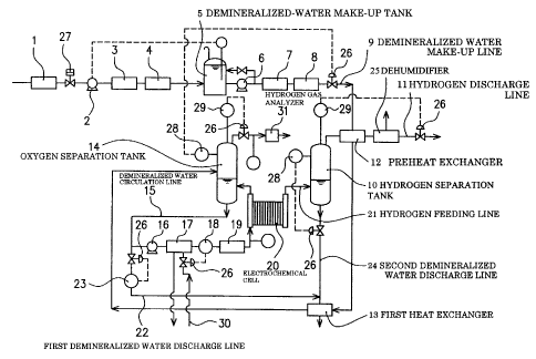
As illustrated in FIG. 1, the water electrolysis device of this embodiment is
designed so that demineralized water fed into electrochemical cell 20 via
demineralized water make-up line 9 is electrolyzed in the electrochemical cell
20 to
generate hydrogen gas and oxygen gas, which are then discharged to the outside
respectively through hydrogen separation tank 10 and oxygen separation tank
14.
The water electrolysis device also includes demineralized water make-up
line 9 for feeding demineralized make-up water to the oxygen separation tank
14,
first heat exchanger 13 interposed in the demineralized water make-up line 9,
demineralized water circulation line 15 extending from the oxygen separation
tank
14 through the electrochemical cell 20 and returned to the oxygen separation
tank
14, hydrogen feeding line 21 extending from the electrochemical cell 20 to the
hydrogen separation tank 10, and first demineralized water discharge line 22
branched off from the demineralized water circulation line 15 and extending
through the first heat exchanger 13 to the outside. The thus arranged first
heat
exchanger 13 is designed to exchange heat between demineralized make-up water
fed through the demineralized water make-up line 9 and demineralized water
discharged to the outside through the first demineralized water discharge line
22.
The water electrolysis device also includes hydrogen supply line 21 for
supplying hydrogen generated in the electrochemical cell 20 to the hydrogen
separation tank 10, and hydrogen discharge line 11 for taking off hydrogen
CA 02392319 2002-05-22
12
separated from demineralized water in the hydrogen separation tank 10.
As illustrated in FIG. 1, interposed in the demineralized water make-up
line 9 are prefilter 1, booster pump 2, first reverse osmosis membrane 3,
second
reverse osmosis membrane 4, demineralized-water make-up tank 5, pump 6, ion
exchange device 7 (made of an ion exchange resin) and final filter 8.
Preferably, preheat exchanger 12 is interposed in the hydrogen discharge
line 11 so that the demineralized water make-up line 9 can extend to the
oxygen
separation tank 14 through the preheat exchanger 12 and the first heat
exchanger
13.
The demineralized water circulation line 15 runs in an endless loop so that
demineralized water is fed from the oxygen separation tank 14 to the
electrochemical cell 20, while oxygen generated and demineralized water
remaining in the electrochemical cell 20 are returned to the oxygen separation
tank
14. Reference numerals 16 and 19 in FIG. 1 respectively represent pump and
final
filter. The final filter 19 is optionally provided, depending on the purity of
the
demineralized water circulation line 15. If extraneous substances are not
mixed
into demineralized water in the demineralized water circulation line 15, the
final
filter 19 may be omitted.
Connected to the hydrogen separation tank 10 is second demineralized
water discharge line 24 for discharging demineralized water with hydrogen gas
removed therefrom. The first demineralized water discharge line 22 joined to
the
second demineralized water discharge line 24 through flow rate
indicating/adjusting device 23 extends to the outside through the first heat
exchanger 13.
Preferably, dehumidifier 25 is disposed on the downstream side of the
preheat exchanger 12 in the hydrogen discharge line 11.
In FIG. 1, reference numerals 26 and 27 respectively represent flow control
CA 02392319 2002-05-22
13
valves and on-off valve respectively installed in the corresponding lines.
Now, the description will be made for operation of the water electrolysis
device. Tap water, which has been fed into the demineralized water make-up
line
9 through its front end, is preliminarily filtered by the prefilter 1,
increased in
pressure by the booster pump 2 through the on-off valve 27, processed to have
a
high purity by the first reverse osmosis membrane 3 and the second reverse
osmosis membrane 4, and then stored in the demineralized-water make-up tank 5.
The demineralized water stored in the demineralized-water make-up tank 5 is
fed
into the oxygen separation tank 14 through the demineralized water make-up
line
9 according to the water level of the oxygen separation tank 14.
In this embodiment, level monitor 28 for monitoring the water level of the
oxygen separation tank 14 is provided, so that the opening of the flow control
valve
26 installed in the demineralized water make-up line 9 is properly adjusted
based
upon a detected value of the level monitor 28. The demineralized water fed
into
the demineralized-water make-up tank 5 under pressure from the pump 6 is fed
into the preheat exchanger 12 through the ion exchange device 7 and the final
filter
8.
In the preheat exchanger 12, the heat is indirectly transferred between
demineralized make-up water fed from the demineralized-water make-up tank 5
and moisture-containing hydrogen gas having a high temperature (about 85 to
120r-) discharged from the hydrogen separation tank 10 after the
electrolyzing.
That is, the demineralized make-up water is increased in temperature by a
predetermined value upon receiving thermal energy from the moisture-containing
hydrogen gas of high temperature. For example, demineralized make-up water
fed, which initially had a temperature of 15-25C, is varied to about 16-26t by
the
preheat exchanger 12.
On the other hand, moisture-containing hydrogen gas in the hydrogen
CA 02392319 2002-05-22
14
discharge line 11 is cooled by demineralized make-up water at the preheat
exchanger 12, thereby generating condensed water from the moisture-containing
hydrogen gas and hence reducing moisture carried to the dehumidifier 25
disposed
on the downstream side of the hydrogen discharge line 11. Accordingly, the
moisture to be removed by the dehumidifier 25 can be reduced, thereby
achieving
downsizing of the dehumidifier 25.
Preferably, the hydrogen discharge line 11 is designed so that the
moisture-containing hydrogen gas flows from the lower side to the upper side
within the preheat exchanger 12, and that the condensed water generated at the
preheat exchanger 12 flows from the preheat exchanger 12 towards the hydrogen
separation tank 10. This arrangement can achieve efficient use of
demineralized
water.
Hydrogen gas with moisture removed therefrom at the dehumidifier 25 is
fed to the use point by the proper adjustment of the opening of the flow
control
valve 26 disposed in the hydrogen discharge line 11 according to a detected
value of
pressure indicating/adjusting device 29, which monitors the pressure within
the
hydrogen separation tank 10. Thus, hydrogen feeding pressure can be kept
constant by controlling the flow rate of the hydrogen discharge line 11
according to
the inner pressure of the hydrogen separation tank 10, and differential
pressure
between an H2-side and an 02-side in the electrochemical cell can be kept
constant,
thereby effectively preventing breakage of a solid polymer electrolyte
membrane.
Demineralized make-up water with its temperature increased by a
predetermined value at the preheat exchanger 12 is subjected at the first heat
exchanger 13 to indirect heat exchange with demineralized water of high
temperature (e.g., about 85- 120 C) discharged through the first demineralized
water discharge line 22 and the second demineralized water discharge line 24.
Whereby, demineralized water with its temperature varied to, for example,
about
CA 02392319 2008-10-28
16-26 C by the preheat exchanger 12 is heated to about 82-119 C and fed into
the
oxygen separation tank 14.
In the water electrolysis device of this embodiment, demineralized water of
high temperature is stored in the oxygen separation tank 14 acting as a
5 demineralized water feeding source to the electrochemical cell 20.
Accordingly, in
this embodiment, an ion exchange resin cannot be used. Therefore, in this
embodiment, the following arrangement is employed to prevent the purity
(specific
resistance) of demineralized water fed to the electrochemical cell 20 from
falling
below a predetermined value (e.g., 5M Q cm) without using the ion exchange
resin.
10 That is, where the volume of demineralized water discharged through the
first demineralized water discharge line 22, which has been branched off from
the
demineralized water circulation line 15, is designated as Q1, and the volume
of
demineralized make-up water fed to the oxygen separation tank 14 through the
demineralized water make-up line 9 is designated as Q2, the openings of the
flow
15 control valves 26 disposed in the demineralized water make-up line 9 and
the first
demineralized water discharge line 22 are properly adjusted so as to have:
Q2?Q,.
In this embodiment, in order to keep the water level of the oxygen
separation tank 14 constant, the flow rates of the respective lines are
controlled.
CA 02392319 2002-05-22
16
Now, the description will be made in detail for the relation between the
volume of demineralized water discharged and the volume of demineralized make-
up water.
In the case of using the ion exchange resin, the specific resistance of
demineralized water is generally increased to 18M S2 cm. Accordingly, if it is
so
designed to enable the total volume of demineralized water with its specific
resistance lowered by using water electrolysis to flow through the ion
exchange
resin, the specific resistance of the demineralized water fed to the
electrochemical
cell is constantly kept at 18M Q cm.
On the other hand, the ion exchange resin has a heat resistant
temperature of about 55t. Accordingly, when the specific resistance of
demineralized water is to be maintained by the ion exchange resin, it is
necessary
to limit the temperature of demineralized water fed to the electrochemical
cell to
about 55 C or lower. However, it is unlikely to achieve a sufficient energy
efficiency if demineralized water to be fed to the electrochemical cell has a
temperature of about 55 O or lower.
As a result of studies with intensive efforts by the present inventors, it has
been found that unusual increase in electrolysis voltage during the water
electrolysis can be prevented if demineralized water to be electrolyzed at the
electrochemical cell has a specific resistance of 5M Q cm or more.
Based upon the above knowledge, the inventors set up a hypothesis that
passing only a part of demineralized water through the ion exchange resin
sufficiently allows the demineralized circulating water to have a specific
resistance
of 5M Sa cm even if the total volume of the demineralized water used for
electrolysis
is not passed therethrough.
The inventors conducted a test described below to establish the hypothesis.
That is, with demineralized circulating water to be used for the water
electrolysis,
CA 02392319 2002-05-22
17
the volume of the demineralized water circulating through the ion exchange
resin
was varied, and the relationship between the proportion of the demineralized
water
circulating through the ion exchange resin and the specific resistance of the
whole
demineralized circulating water was investigated. The test result is
illustrated in
FIG.4.
As illustrated in FIG. 4, the higher the proportion of the demineralized
water flowing through the ion exchange resin with respect to the demineralized
circulating water is, the higher the specific resistance of the demineralized
circulating water is. It can be seen that at least 3.5% of the proportion of
the
demineralized water flowing through the ion exchange resin is enough to assure
at
least 5M S2 cm of the specific resistance of the demineralized circulating
water.
Meanwhile, the demineralized make-up water also has a specific
resistance of 18M Sa cm, which is the same as that of the demineralized water
which
has flown through the ion exchange resin. Accordingly, instead of making a
part of
the demineralized circulating water flow through the ion exchange resin, a
part of
the demineralized circulating water is discharged to the outside while highly
demineralized water of a volume at least equivalent to the discharged volume
is
added to the demineralized circulating water, so that the specific resistance
of the
demineralized circulating water can be maintained. That is, at least 3.5% of
the
whole volume of the demineralized circulating water is discharged to the
outside,
and alternatively, highly demineralized make-up water having a volume at least
equivalent to the discharged volume is fed to the demineralized water
circulation
line, so that the demineralized circulating water can retain a specific
resistance of
at least 5M Q cm without using the ion exchange resin.
Thus, in the water electrolysis device of this embodiment, there are
provided the demineralized water circulation line 15 that is capable of
feeding
demineralized water from the oxygen separation tank 14 to the electrochemical
cell
CA 02392319 2002-05-22
18
20 and returning the demineralized water remaining in the electrochemical cell
20
to the oxygen separation tank 14, the first demineralized water discharge line
22
that discharges a part of the demineralized water in the oxygen separation
tank 14
to the outside, and the demineralized water make-up line 9 that feeds highly
demineralized water to the oxygen separation tank 14. With the thus arranged
water electrolysis device, the ion concentration of demineralized water to be
fed to
the electrochemical cell 20 can be lowered (or the specific resistance thereof
is
increased) despite of non-use of the ion exchange resin.
It is so designed that when a part of demineralized water in the oxygen
separation tank 14, which contains demineralized water subjected to the water
electrolysis and returned from the electrochemical cell 20, is discharged to
the
outside through the first demineralized water discharge line 22, thermal
energy
possessed by the demineralized water discharged to the outside is transmitted
by
the first heat exchanger 13 to highly demineralized water fed to the oxygen
separation tank 14 through the demineralized water make-up line 9. Therefore,
according to this embodiment, the temperature of the demineralized water fed
to
the electrochemical cell 20 can be kept higher than a predetermined level,
enabling
highly demineralized water having a high temperature to be fed to the
electrochemical cell 20. Hence, the water electrolysis can be carried out with
high
energy efficiency.
Where the temperature of demineralized water circulating in the
demineralized water circulation line 15 is heated to 80t or higher, it is
likely to
disadvantageously cause deterioration of seal members such as 0-rings, gaskets
or
the like, which are module components. Therefore, the temperature of
demineralized water fed to the electrochemical cell 20 is preferably set lower
than
80C.
In this embodiment, heat exchanger 17 and thermometer 18 are interposed
CA 02392319 2002-05-22
19
in the demineralized water circulation line 15 between the oxygen separation
tank
14 and the electrochemical ce1120, in which the flow rate of cold water
feeding line
30 connected with the heat exchanger 17 is adjusted by the flow control valve
26 so
as to adjust the temperature of demineralized water detected by the
thermometer
18 to 809C or lower.
As an preferable arrangement, by making the pressure
indicating/adjusting device 29 or the like detect the inner pressure of the
oxygen
separation tank 14, oxygen in the oxygen separation tank 14 is released to the
atmosphere through the flow control valve 26 if the inner pressure exceeds a
predetermined value. Whereby, the pressure in the oxygen separation tank 14
can
be kept to a predetermined level or lower, thereby keeping constant the
differential
pressure between the H2-side and the 02-side in the electrochemical cell and
hence
effectively preventing breakage of the solid polymer electrolyte membrane. As
a
more preferable arrangement, as illustrated in FIG. 1, hydrogen gas analyzer
31 is
provided in an oxygen releasing line to raise an alarm if the hydrogen
concentration in the oxygen releasing line exceeds a predetermined value. This
can effectively prevent dangerous events such as explosion caused by mixing of
hydrogen and oxygen.
In this embodiment, as illustrated in FIG. 1, demineralized water in the
first demineralized water discharge line 22 flows into demineralized water in
the
second demineralized water discharge line 24, and heat is exchanged with
demineralized make-up water in the demineralized water make-up line 9 through
the single heat exchanger 13. Alternatively to this, two heat exchangers may
be
provided to achieve heat exchanges independently of each other.
A method of independent heat exchange, which is achieved by an
arrangement with second preheat exchanger 32 disposed on the front side of the
first heat exchanger 13 in the demineralized water make-up line 9 as
illustrated in
CA 02392319 2002-05-22
FIG. 2, includes indirectly exchanging heat at the second preheat exchanger 32
between demineralized water discharged through the second demineralized water
discharge line 24 and demineralized water flowing through the demineralized
water make-up line 9, and indirectly exchanging heat at the first heat
exchanger 13
5 between demineralized make-up water with its heat transferred at the second
preheat exchanger 32 and demineralized water discharged through the first
demineralized water discharge line 22. Alternatively, the method, which is
achieved by an arrangement with the demineralized water make-up line 9 divided
into two lines 9a, 9b, and heat exchangers 33, 34 respectively disposed in
these
10 lines, as illustrated in FIG. 3, includes indirectly exchanging heat at the
heat
exchanger 33 between demineralized water discharged through the second
demineralized water discharge line 24 and demineralized make-up water flowing
through the divided line 9a, and indirectly exchanging heat at the heat
exchanger
34 between demineralized water discharged through the first demineralized
water
15 discharge line 22 and demineralized make-up water flowing through the
divided
line 9b. However, according to the former method, an efficient heat exchange
may
not be achieved since the temperature of the demineralized make-up water has
greatly been increased at the second preheat exchanger 32. Therefore, the
latter
method is preferable in respect of the heat exchange efficiency.
20 Thus, the arrangement, where the demineralized water discharged
through the first demineralized water discharge line 22 and the demineralized
water discharged through the second demineralized water discharge line 24 do
not
flow into each other, but are discharged to the outside independently of each
other,
can effectively prevent variation of the discharge rate due to difference in
back
pressure between the flow control valves 26 respectively installed in the
first
demineralized water discharge line 22 and the second demineralized water
discharge line 24. As a result, the flow control can be stably performed.
CA 02392319 2002-05-22
21
Whether or not the first demineralized water discharge line 22 and the
second demineralized water discharge line 24 are joined to each other, the
discharged demineralized water with its heat tra.nsfe.r.recl at the heat
exchanger
can be returned to the demineralized water make-up tank 5, thereby achieving
reduced consumption of demineralized water.
In this embodiment, the first demineralized water discharge line 22 has a
proximal end communicated with the demineralized water circulation line 15.
However, the present invention is not necessarily limited to this embodiment.
As
far as a part of the residual demineralized water returned from the
electrochemical
cell 20 after electrolysis is discharged to the outside through the first
demineralized
water discharge line 22, various embodiments are applicable. For example, the
proximal end of the first demineralized water discharge line 22 may be
arranged in
communication with the oxygen separation tank 14.