Some of the information on this Web page has been provided by external sources. The Government of Canada is not responsible for the accuracy, reliability or currency of the information supplied by external sources. Users wishing to rely upon this information should consult directly with the source of the information. Content provided by external sources is not subject to official languages, privacy and accessibility requirements.
Any discrepancies in the text and image of the Claims and Abstract are due to differing posting times. Text of the Claims and Abstract are posted:
| (12) Patent: | (11) CA 2392437 |
|---|---|
| (54) English Title: | CABLE DRUM |
| (54) French Title: | TAMBOUR D'ENROULEMENT DE CABLE |
| Status: | Expired and beyond the Period of Reversal |
| (51) International Patent Classification (IPC): |
|
|---|---|
| (72) Inventors : |
|
| (73) Owners : |
|
| (71) Applicants : |
|
| (74) Agent: | SMART & BIGGAR LP |
| (74) Associate agent: | |
| (45) Issued: | 2006-09-19 |
| (22) Filed Date: | 2002-07-04 |
| (41) Open to Public Inspection: | 2003-01-05 |
| Examination requested: | 2002-09-23 |
| Availability of licence: | N/A |
| Dedicated to the Public: | N/A |
| (25) Language of filing: | English |
| Patent Cooperation Treaty (PCT): | No |
|---|
| (30) Application Priority Data: | ||||||
|---|---|---|---|---|---|---|
|
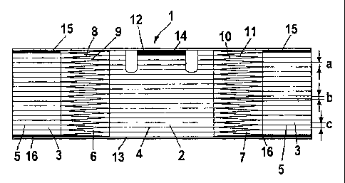
A cable drum, comprising a substantially cylindrical drum body (21), having drum walls (12, 13) arranged at its axial ends, and comprising a groove arrangement arranged on the drum body (21), enables winding of a cable in a rotational direction in the clockwise direction as well as counter thereto. The groove arrangement has at least one parallel area (2, 3) in which the grooves (4, 5) extends parallel to the circumferential direction and at least one incline area (6, 7) in which the grooves (8, 9, 10, 11) are slanted at an angle relative to the circumferential direction. All grooves (4, 5) in the parallel areas (2, 3) have the same groove width (a). The grooves (8, 9, 10, 11) in the incline area (6, 7) cross one another.
L'invention concerne un tambour d'enroulement de câble, comprenant un corps de tambour (21) sensiblement cylindrique et présentant des parois de tambour (12, 13) agencées en ses extrémités axiales, et comprenant un agencement de rainures agencées sur le corps de tambour (21), qui permet d'enrouler un câble dans une direction de rotation dans le sens des aiguilles d'une montre ainsi que dans le sens inverse des aiguilles d'une montre. L'agencement de rainures présente au moins une zone parallèle (2, 3) dans laquelle les rainures (4, 5) se prolongent parallèlement à la direction circonférentielle et au moins une zone en pente (6, 7) dans laquelle les rainures (8, 9, 10, 11) sont inclinées selon un angle par rapport à la direction circonférentielle. Toutes les rainures (4, 5) situées dans les zones parallèles (2, 3) sont de même largeur (a). Les rainures (8, 9, 10, 11) situées dans la zone en pente (6, 7) se croisent.
Note: Claims are shown in the official language in which they were submitted.
Note: Descriptions are shown in the official language in which they were submitted.
2024-08-01:As part of the Next Generation Patents (NGP) transition, the Canadian Patents Database (CPD) now contains a more detailed Event History, which replicates the Event Log of our new back-office solution.
Please note that "Inactive:" events refers to events no longer in use in our new back-office solution.
For a clearer understanding of the status of the application/patent presented on this page, the site Disclaimer , as well as the definitions for Patent , Event History , Maintenance Fee and Payment History should be consulted.
| Description | Date |
|---|---|
| Time Limit for Reversal Expired | 2018-07-04 |
| Change of Address or Method of Correspondence Request Received | 2018-03-28 |
| Letter Sent | 2017-07-04 |
| Grant by Issuance | 2006-09-19 |
| Inactive: Cover page published | 2006-09-18 |
| Inactive: Final fee received | 2006-07-06 |
| Pre-grant | 2006-07-06 |
| Notice of Allowance is Issued | 2006-04-19 |
| Letter Sent | 2006-04-19 |
| Notice of Allowance is Issued | 2006-04-19 |
| Inactive: IPC from MCD | 2006-03-12 |
| Inactive: IPC from MCD | 2006-03-12 |
| Inactive: Approved for allowance (AFA) | 2006-02-28 |
| Amendment Received - Voluntary Amendment | 2006-01-10 |
| Inactive: S.30(2) Rules - Examiner requisition | 2005-10-05 |
| Inactive: Cover page published | 2003-01-05 |
| Application Published (Open to Public Inspection) | 2003-01-05 |
| Letter Sent | 2002-11-05 |
| Letter Sent | 2002-11-04 |
| Request for Examination Received | 2002-09-23 |
| Request for Examination Requirements Determined Compliant | 2002-09-23 |
| All Requirements for Examination Determined Compliant | 2002-09-23 |
| Inactive: Single transfer | 2002-09-23 |
| Inactive: First IPC assigned | 2002-09-09 |
| Inactive: Courtesy letter - Evidence | 2002-08-27 |
| Inactive: Filing certificate - No RFE (English) | 2002-08-21 |
| Application Received - Regular National | 2002-08-21 |
There is no abandonment history.
The last payment was received on 2006-06-29
Note : If the full payment has not been received on or before the date indicated, a further fee may be required which may be one of the following
Patent fees are adjusted on the 1st of January every year. The amounts above are the current amounts if received by December 31 of the current year.
Please refer to the CIPO
Patent Fees
web page to see all current fee amounts.
| Fee Type | Anniversary Year | Due Date | Paid Date |
|---|---|---|---|
| Application fee - standard | 2002-07-04 | ||
| Registration of a document | 2002-09-23 | ||
| Request for examination - standard | 2002-09-23 | ||
| MF (application, 2nd anniv.) - standard | 02 | 2004-07-05 | 2004-06-15 |
| MF (application, 3rd anniv.) - standard | 03 | 2005-07-04 | 2005-06-22 |
| MF (application, 4th anniv.) - standard | 04 | 2006-07-04 | 2006-06-29 |
| Final fee - standard | 2006-07-06 | ||
| MF (patent, 5th anniv.) - standard | 2007-07-04 | 2007-06-26 | |
| MF (patent, 6th anniv.) - standard | 2008-07-04 | 2008-06-30 | |
| MF (patent, 7th anniv.) - standard | 2009-07-06 | 2009-06-22 | |
| MF (patent, 8th anniv.) - standard | 2010-07-05 | 2010-06-17 | |
| MF (patent, 9th anniv.) - standard | 2011-07-04 | 2011-06-28 | |
| MF (patent, 10th anniv.) - standard | 2012-07-04 | 2012-06-22 | |
| MF (patent, 11th anniv.) - standard | 2013-07-04 | 2013-06-25 | |
| MF (patent, 12th anniv.) - standard | 2014-07-04 | 2014-06-24 | |
| MF (patent, 13th anniv.) - standard | 2015-07-06 | 2015-06-19 | |
| MF (patent, 14th anniv.) - standard | 2016-07-04 | 2016-06-21 |
Note: Records showing the ownership history in alphabetical order.
| Current Owners on Record |
|---|
| ROTZLER GMBH + CO.KG |
| Past Owners on Record |
|---|
| RALF BRUTSCHIN |

