Note: Descriptions are shown in the official language in which they were submitted.
CA 02392457 2002-05-23
WO 01/48843 PCT/CA00/01490
FUEL CELL SEPARATOR PLATE WITH
DISCRETE FLUID DISTRIBUTION FEATURES
Field of the Invention
The present invention relates to a separator
plate for a fuel cell. The separator plate comprises
at least one discrete fluid distribution feature
such as, for example, an open channel formed in a
major surface of the separator plate. More
particularly, within the thickness of the separator
plate, the fluid distribution feature is fluidly
isolated from fluid inlets or outlets.
Background of the Invention
Electrochemical fuel cells convert reactants,
namely fuel and oxidants, to generate electric power
and reaction products. Electrochemical fuel cells
generally employ an electrolyte disposed between two
electrodes, namely a cathode and an anode. The
electrodes each comprise electrocatalyst disposed at
the interface between the electrolyte and the
electrodes to induce the desired electrochemical
reactions. The location of the electrocatalyst
typically defines the electrochemically active area
of the electrode. The electrode layers are
electrically conductive and fluid permeable, so that
the reactant fluids may flow to the electrocatalyst
sites from the fuel cell reactant inlet.
The fuel fluid stream which is supplied to the
anode may be a gas such as substantially pure
hydrogen or a reformate stream comprising hydrogen.
Alternatively, a liquid fuel stream such as, for
example, aqueous methanol may be used. The oxidant
fluid stream, which is supplied to the cathode,
CA 02392457 2002-05-23
WO 01/48843 PCT/CA00/01490
- 2 -
typically comprises oxygen, such as substantially
pure oxygen, or a dilute oxygen stream such as air.
Solid polymer fuel cells employ a solid polymer
electrolyte, or ion exchange membrane. The membrane
is typically interposed between two electrode
layers, forming a membrane electrode assembly
("MEA"). While the membrane is typically proton
conductive, it also acts as a barrier, isolating the
fuel and oxidant streams from each other on opposite
sides of the MEA. The MEA is typically disposed
between two plates to form a fuel cell assembly.
The plates act as current collectors and provide
support for the adjacent electrodes. The assembly
is typically compressed to ensure good electrical
contact between the plates and the electrodes, in
addition to adequate sealing between fuel cell
components.
A plurality of fuel cell assemblies may be
combined and electrically connected in series or in
parallel, to form a fuel cell stack. In a fuel cell
stack, a plate may be shared between two adjacent
fuel cell assemblies, in which case the plate also
serves as a separator to fluidly isolate the fluid
streams of the two adjacent fuel cell assemblies.
Fuel cell plates, known as separator plates,
may have open channels formed in one or both
opposing major surfaces for directing reactants
and/or coolant fluids to specific portions of such
major surfaces. The open channels also provide
passages for the removal of reaction products,
depleted reactant streams, and/or heated coolant
streams. U.S. Patent No. 4,988,583 sets forth
figures that illustrate an example of a fuel cell
separator plate which has an open serpentine channel
formed on a major surface of the plate. In this
CA 02392457 2002-05-23
WO 01/48843 PCT/CA00/01490
- 3 -
example, the channel is continuous, that is, fluidly
connected to a fluid inlet and to a fluid outlet.
U.S. Patent No. 5,300,370 ("the '370 patent")
discloses several fluid channel configurations
formed in a major surface of fuel cell separator or
flow field plates. For example, FIG. 8 of the '370
patent illustrates a plurality of parallel
continuous channels which are each fluidly connected
to an inlet and an outlet. FIG. 9 of the '370
patent illustrates a flow field plate that employs
discontinuous flow field channels, but each of these
channels is fluidly connected by an open-faced
channel to one of the fluid inlet or the fluid
outlet.
One approach to improving fuel cell performance
is to increase the open channel area to increase
contact between the reactant streams flowing in the
channels and the adjacent electrochemically active
area of the adjacent electrode. Performance is
improved by increasing the accessibility of the
reactant fluids to the electrocatalyst at the
interface between the electrolyte and the electrode.
A purpose of the open-faced flow field channels
formed in the separator plates is to direct the
reactant fluids across substantially the whole of
the electrochemically active area. These open-faced
channels are defined by adjoining "land areas" that
contact and support the electrode layer, thereby
substantially preventing the electrode from
deflecting into the open channel. However, reactant
fluids will generally travel through the fuel cell
from an inlet to an outlet along the path that
offers the lowest pressure 1055. The pressure loss
sustained when the reactant fluid travels along the
channel is typically less than the pressure loss
CA 02392457 2002-05-23
WO 01/48843 PCT/CA00/01490
- 4 -
that would be sustained if the reactant fluid were
to flow through the fluid permeable electrode.
Therefore, when a continuous channel is provided
between a fuel cell inlet and a fuel cell outlet,
the majority of the reactant fluid stream will
travel within the channel and diffuse into the
electrode areas mostly in the regions next to the
open-faced channels. A problem with conventional
flow field arrangements is that reactant fluids
typically only have limited access to the electrode
areas adjacent the land areas by diffusion, and some
degree of "flow" if there is a consistent pressure
differential between channels on opposite sides of a
land area. For this reason, conventional flow field
plates tend to be designed to increase the open
channel area and reduce the land areas.
However, because the land areas are needed to
support the electrode and provide an electrically
conductive path from the electrodes to the separator
plates for current collection, a compromise must be
made between reducing the size of the land areas to
increase direct exposure of the electrodes to the
reactant fluid flowing in the channel, and providing
sufficiently sized land areas for adequately
supporting the electrode layer and providing
adequate electrical conductance for current
collection.
Since there may be little or no fluid flow to
the electrode layer where it contacts the separator
plate land areas, water may accumulate within the
electrode layer in these areas. The accumulation of
water may compound the problem by flooding the
electrode in the portions adjacent the land areas,
thus making the flooded areas even less accessible
to the reactant fluids.
CA 02392457 2002-05-23
WO 01/48843 PCT/CA00/01490
Stunxnary of the Invention
An electrically conductive, substantially fluid
impermeable separator plate for an electrochemical
cell comprises:
(a) a substantially planar major surface for
facing a fluid permeable electrode of the
electrochemical cell;
(b) a fluid inlet through which a fluid may be
directed to the planar major surface;
(c) a fluid outlet through which fluid may be
removed from the planar major surface;
(d) at least one discrete fluid distribution
feature formed in the planar major surface
wherein, within the thickness of the
plate, the fluid distribution feature is
fluidly isolated from the fluid inlet and
the fluid outlet.
In a preferred embodiment, the electrochemical
cell is a solid polymer fuel cell.
The discrete fluid distribution feature is
preferably a channel that is oriented substantially
perpendicular to the direction of fluid flow to and
from the discrete distribution channel. That is,
unlike conventional flow field channels, where the
majority of the fluid travels in the same direction
as the channel orientation (along the length of the
channel), in preferred. embodiments, fluid flowing
to/from the discrete fluid distribution channel
enters or exits the discrete fluid distribution
channel along a flow path that is substantially
perpendicular to the longitudinal orientation of the
discrete fluid distribution channel. In the present
flow field fluid distribution areas where there are
CA 02392457 2002-05-23
WO 01/48843 PCT/CA00/01490
- 6 -
discrete fluids di~~tribution channels, in addition to
fluid flow alon-the discrete fluid distribution
channel, the fluid is directed across the land areas
between adjacent discrete fluid distribution
channels and/or adjacent inlet or outlet channels.
For a separator plate that comprises a
plurality of discrete fluid distribution channels
that are oriented substantially parallel to one
another, the fluid preferably flows between adjacent
discrete fluid distribution channels in a direction
that is perpendicular to the discrete fluid
distribution channels.
In embodiments that further comprise inlet or
outlet channels extending from, and in fluid
communication, with respective inlet or outlet
openings or manifolds, the respective inlet or
outlet channels are preferably substantially
parallel with the at least one discrete fluid
distribution channel, and fluid flows between the
discrete fluid distribution channel and the inlet or
outlet channel in a direction that is substantially
perpendicular to the discrete fluid distribution
channel and the inlet and/or outlet channels.
In preferred embodiments the discrete fluid
distribution channel is oriented substantially
perpendicular to a straight line drawn between the
fluid inlet and the fluid outlet. In other
preferred embodiments the discrete fluid
distribution channel is oriented substantially
parallel to a straight line drawn between the fluid
inlet and the fluid outlet.
The substantially planar major surface of the
separator plate preferably comprises a fluid
distribution area that corresponds to and is co-
extensive with the electrochemically active area of
CA 02392457 2002-05-23
WO 01/48843 PCT/CA00/01490
the adjacent electrode when the separator plate is
part of a fuel cell assembly. The discrete fluid
distribution channel is preferably a substantially
straight channel that extends substantially between
opposing edges of the fluid distribution area. In
one preferred embodiment the fluid distribution area
is substantially in the shape of a rectangle and the
discrete fluid distribution channel is substantially
aligned with the longitudinal axis of the fluid
distribution area.
A preferred embodiment of the separator plate
comprises a hybrid fluid distribution area that
comprises one or more serpentine channels and at
least one discrete straight fluid distribution
IS channel. For example, the major planar surface
comprises at least one serpentine fluid channel that
extends from at least one of the fluid inlet and the
fluid outlet. The serpentine fluid channel extends
over a portion of the planar major surface, while at
least one discrete fluid distribution channel
extends over another portion of the fluid
distribution area.
The separator plate preferably further
comprises openings penetrating the plate for forming
fluid manifolds when the plate is one of a plurality
of plates placed one on top of the other to form a
fuel cell stack. The openings are aligned in
adjacent plates, and are typically fluidly connected
to fluid passages formed in the fuel cell stack end
plate assemblies.
The features formed in the major planar surface
of the separator plate may be formed by embossing a
material comprising expanded graphite. More
particularly, when the plate material is a formable
material like expanded graphite, any of the plate
CA 02392457 2002-05-23
WO 01/48843 PCT/CA00/01490
- g -
features, which may include, for example, one or
more discrete fluid distribution channels, inlet
channel(s), outlet channel(s), grooves for receiving
seals, and fluid manifold openings, may be formed by
embossing methods.
In another embodiment, the separator plate may
be made from a molded composite material comprisirzg
carbon. The carbon component provides electrical
conductivity and is compatible with the operating
environment and the fluids that flow through
conventional solid polymer electrolyte fuel cells.
As an alternative to using a molding process to form
the discrete fluid distribution channel, a die
cutter or mill may be employed to cut the discrete
channel into the major planar surface of the plate.
The separator plate may be impregnated with
resin to improve the desired mechanical properties
such as durability, impermeability, and
hydrophobicity. The plate is preferably hydrophobic
to facilitate the flow of water within the fluid
distribution area. It is important to facilitate
water flow within the fluid distribution area
because water is needed to keep the electrolytic
membrane moist to increase its ion conductivity. It
is equally important for excess water to be removed
from the fluid distribution area to prevent flooding
which might prevent reactants from accessing the
electrochemically active areas of the electrode.
In a preferred embodiment, the discrete fluid
distribution channel has a substantially uniform
cross-sectional area along its length. In essence,
each of the discrete fluid distribution channels
acts as a fluid header for distributing reactant
fluid along the length of the discrete channel. A
uniform channel cross-section promotes a more even
CA 02392457 2002-05-23
WO 01/48843 PCT/CA00/01490
- 9 -
distribution of the reactant along the length of the
discrete channel.
The present separator plate is preferably
employed in an electrochemical fuel cell stack that
comprises:
(a) a plurality of membrane electrode
assemblies comprising a pair of fluid
permeable electrodes, wherein each one of
the membrane electrode assemblies is
interposed between planar major surfaces
of two substantially fluid impermeable
separator plates; and
(b) at least one discrete fluid distribution
feature (preferably a discrete channel)
formed in one of the planar major surface
of at least one of the two plates, wherein
within the thickness of the respective one
of the separator plates, the fluid
distribution channel is fluidly isolated
such that it is not connected to a fluid
inlet or a fluid outlet by any fluid
conduits within the thickness of the
respective one of the separator plates.
The at least one discrete fluid distribution
channel is preferably one of a plurality of discrete
fluid distribution channels which are each fluidly
isolated within the thickness of the respective one
of the flow field plates. The plurality of discrete
fluid distribution channels are preferably
substantially parallel to one another, so that the
reactant fluid flowing across the fluid distribution
area is distributed across substantially the entire
area.
CA 02392457 2002-05-23
WO 01/48843 PCT/CA00/01490
- 10 -
Brief Description of the Drawings
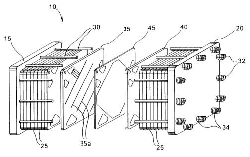
FIG. 1 i:~:~n exploded perspective view of a
fuel cell stack that comprises a separator plate
that has discrete fluid distribution channels.
FIG. 2 is an exploded schematic section view of
a solid polymer fuel cell comprising a membrane
electrode assembly interposed between two separator
plates which each comprise a plurality of discrete
fluid distribution channels.
FIG. 3 is a plan view of a major surface of a
fuel cell separator plate that comprises a plurality
of discrete fluid distribution channels.
FIG. 4 is a plan view of a major surface of a
fuel cell separator plate, similar in shape to the
plate of FIG. 3, except that the discrete fluid
distribution channels are more closely spaced.
FIG. 5 is a plan view of a major surface of an
elongated fuel cell separator plate that comprises a
plurality of discrete fluid distribution channels,
parallel to the longitudinal axis.
FIG. 6 is a plan view of a major surface of a
fuel cell separator plate that comprises a plurality
of discrete fluid distribution channels on a portion
of the major surface and a serpentine channel that
extends from a reactant fluid inlet.
Detailed Description of Preferred Embodiments
FIG. 1 illustrates, in exploded view, a solid
polymer electrochemical fuel cell stack 10,
including a pair of end plate assemblies 15, 20 and
a plurality of fuel cell assemblies 25. Tie rods 30
extend between end plate assemblies 15 and 20 to
retain and secure stack assembly 10 in its assembled
state with fastening nuts 32. Springs 34 disposed
on tie rods 30, are interposed between the fastening
CA 02392457 2002-05-23
WO 01/48843 PCT/CA00/01490
- 11 -
nuts 32 and the end plate 20 to apply resilient
compressive force to the stack in the longitudinal
direction. Reactant and optionally coolant fluid
streams are supplied to and exhausted from internal
manifolds and passages in stack 10 via stack inlet
and outlet ports (not shown) in end plate 15.
As shown by the exploded portion of FIG. 1,
each fuel cell assembly 25 comprises a MEA 45 which
is interposed between two fuel cell separator
plates, namely an anode flow field plate 35, and a
cathode flow field plate 40. MEA 45 itself
comprises an ion exchange membrane interposed
between a fluid permeable anode and a fluid
permeable cathode.
Anode flow field plate 35 has a plurality of
discrete fluid distribution channels 35a formed in
its major surface facing MEA 45 to assist with the
distribution of a fuel fluid stream across the
electrochemically active areas of the fluid
permeable anode. Cathode flow field plate 40 may
also comprise features (not shown), similar to anode
flow field plate 35, to assist with the e~
distribution of an oxidant fluid stream across the
electrochemically active areas of the fluid
permeable cathode. For example, cathode flow field
plate 40 may comprise features such as discrete
and/or continuous channels for distributing oxidant
to the cathode from an oxidant inlet and exhausting
a cathode exhaust stream from the cathode to an
oxidant outlet.
FIG. 2 is an exploded schematic section view of
a fuel cell 100 (not to scale) that comprises anode
flow field plate 135, a cathode flow field plate
140, and MEA 145 interposed therebetween. Anode
flow field plate 135 comprises discrete fuel
CA 02392457 2002-05-23
WO 01/48843 PCT/CA00/01490
- 12 -
distribution channels 135a separated by land areas
137. Cathode flow field plate 140 comprises
discrete oxidant distribution channels 140a
separated by land areas 142.
MEA 145 comprises an electrolyte layer 150,
interposed between fluid permeable anode 155 and
fluid permeable cathode 160. Seals prevent the
reactant fluids from leaking from the fuel cell
assembly and from passing from one electrode to the
other. For example, in the illustrated embodiment,
a sealant material 165 encapsulates the edge regions
of MEA 145 and impregnates an edge portion of anode
155 and cathode 160, thus providing a seal that is
an integral part of MEA 145. Electrocatalyst (not
shown) is disposed at the interfaces between
electrolyte layer 150 and anode 155 and cathode 160.
With reference, for example, to anode flow
field plate 135, discrete fuel distribution channels
135a, improve the utilization of catalyst in the
electrochemically active area of anode 155 because
there are no fluid passages between discrete fuel
distribution channels 135a within the thickness of
plate 135. Therefore, the pressure differential
between the fuel inlet (not shown in FIG. 2) and the
fuel outlet (not shown in FIG. 2) directs the fuel
fluid through the fluid permeable anode from one
discrete fluid distribution channel 135a to the next
(see arrow 170). In this manner, discrete fluid
distribution channels 135a assist in distributing
the fuel fluid to areas of anode 155 adjacent land
areas 137 all along the length of discrete channels
135a, in addition to areas of anode 155 directly
adjacent discrete fuel distribution channels 135a.
Accordingly, a benefit of employing discrete fluid
distribution channels 135a is improved catalyst
CA 02392457 2002-05-23
WO 01/48843 PCT/CA00/01490
- 13 -
utilization at the anode, because contact between
the fuel fluid and the anode electrochemically
active area is promoted both in the portions of the
anode that are adjacent fluid distribution channels
135a and the portions of the anode that are adjacent
land areas 137. At cathode 160 discrete oxidant
distribution channels 140a operate in a similar way
to fuel distribution channels 135a, to also yield
the improved fluid distribution and increased
cathode catalyst utilization in the
electrochemically active area of cathode 160.
The section view of FIG. 2 shows how, within
the thickness of anode flow field plate 135 and
cathode flow field plate 140, the respective
discrete fluid distribution channels 135a and 140a
are fluidly isolated from one other and from the
inlet and outlet (not shown). In fact, as indicated
above, it is this feature that provides improved
fluid distribution.
FIG. 3 shows an example of a fuel cell
separator plate 300 that comprises a plurality of
discrete fluid distribution channels 310. Groove
315 is provided for receiving a sealant material
that may be, for example, a gasket or another
sealant material that is deposited on the plate or
the MEA. Openings 320 and 325, penetrate through
plate 300 and align with openings in adjacent plates
and MEAs to form fluid manifolds when plate 300 is
part of a fuel cell stack (see, for example, FIG.
1). For example, openings 320 may supply oxidant to
the fluid distribution area circumscribed by seal
groove 315, and opening 325 may act as an oxidant
outlet manifold for exhausting oxidant from the
fluid distribution area. In this example, openings
330 and 335 may serve as a portion of respective
CA 02392457 2002-05-23
WO 01/48843 PCT/CA00/01490
- 14 -
fuel inlet anti outlet manifolds, and openings 340
and 345 may ser-~,re as a portion of respective coolant
inlet and outlet manifolds. As shown in FIG. 3,
seal groove 315 also circumscribes openings 330,
335, 340 and 345 to prevent the oxidant stream from
mixing with the fuel and coolant fluid streams.
FIG. 3 shows in plan view how land areas 350
fluidly isolate discrete fluid distribution channels
310 from one another within the thickness of the
plate. Fluid distribution channels 310 extend
substantially between opposing edges of the fluid
distribution area, and are oriented substantially
perpendicular to the direction of a straight line
drawn between inlet manifold opening 320 and outlet
manifold opening 325. Continuing the example where
the reactant fluid supplied through opening 320 is
an oxidant supply stream, oxidant inlet channel 320a
receives oxidant from the oxidant stream inlet
manifold (opening 320). The pressure loss sustained
by the oxidant traveling from opening 320 to the
outlet manifold (opening 325) by any direct path is
theoretically the same. For example, the pressure
loss sustained by a portion of the oxidant stream
that travels to the furthest end of channel 320a and
travels across the lower portion of plate 300 to
opening 325 theoretically is the same pressure loss
as a portion of the oxidant stream that travels
across the top of plate 300 and down the length of
outlet channel 325a which leads to outlet manifold
opening 325. Similarly, the same pressure loss is
theoretically sustained by the portion of the
oxidant stream that travels across the middle of
plate 300. Since the oxidant stream will tend to
take the path which yields the lowest pressure loss,
the path traveled between adjacent discrete fluid
CA 02392457 2002-05-23
WO 01/48843 PCT/CA00/01490
- 15 -
distribution channels 310 will generally be direct
and substantially perpendicular to channels 310
(that is, the shortest path). The natural tendency
for the fluid to travel along paths that will
minimize the pressure loss prevents all of the
oxidant from taking the same path and encourages a
generally even fluid distribution since every path
results in substantially the same theoretical
pressure loss.
In the illustrated example, plate 300 is a
plate that is about 8.125 square inches (52.42 cm2).
In preferred embodiments, plate 300 may be made
from a carbon composite material. Discrete fluid
distribution channels 310 have centerlines that are
spaced apart by 0.6 inch (1.52 cm) and channels 310
are 0.050 inch (0.127 cm) deep and 0.053 inch (0.135
cm) wide (that is, the land area between adjacent
channels is about 0.547 inch (1.389 cm) wide).
Those skilled in the art will understand that these
preferred dimensions will vary from fuel cell to
fuel cell. In addition, the examples of FIGS. 4 and
6 show that other spacing between discrete fluid
distribution channels may be used, or that other
shapes may be employed for the separator plate.
In particular, FIG. 4 is a plan view of another
embodiment of a fuel cell flow field plate 400 that
comprises a plurality of discrete fluid distribution
channels 410. In this embodiment, only two fluid
carrying openings 420 and 425 are provided. Sealing
area 430 provides a sealing surface for receiving a
sealant material to provide a seal for containing
the reactant fluid within the fluid distribution
area.
In a single cell arrangement only two openings
are required since each flow field plate 400 is
CA 02392457 2002-05-23
WO 01/48843 PCT/CA00/01490
- 16 -
interposed between the MEA and an end plate.
Because flow field plate 400 has only two fluid
openings (420 and 425), more of the plate area can
be used for fluid distribution and the corresponding
active area of the adjacent MEA may be made larger.
In the example illustrated by FIG. 4, plate 400 is
an 8.125 square inches (52.42 cm2) plate made from a
carbon composite material. In this example, discrete
fluid distribution channels 410 are engraved in the
major surface of plate 300. Discrete fluid
distribution channels 410 are 0.05 inch (0.13 cm)
deep and 0.053 inch (0.135 cm) wide. The spacing
between the centerlines of adjacent discrete fluid
distribution channels is 0.09 inch (0.23 cm) (that
is, in this example, the width of the land areas
between adjacent fluid distribution channels is
0.037 inch (0.094 cm). Compared to plate 300 shown
in FIG. 3, which has similarly dimensioned discrete
fluid distribution channels, the pressure loss for
the fluid traveling across plate 400, would be lower
across the same distance because there are more
fluid distribution channels 410, and the pressure
loss for the fluid to cross the open channel area is
less than the pressure loss for the fluid to cross
the land areas (through the thickness of the
adjacent fluid permeable electrode). In general,
the effect of the number of discrete fluid
distribution channels depends upon the overall
channel open area versus the overall land area since
the pressure loss sustained by crossing the land
areas is much greater than the pressure loss
sustained in crossing the open channels. However,
an important effect of increasing the number of
discrete fluid distribution channels is that this
generally improves fluid mobility in the transverse
CA 02392457 2002-05-23
WO 01/48843 PCT/CA00/01490
- 17 -
direction along the length of the channel.
Still with reference to FIG. 4, plate 400 may
also be used in a fuel cell stack, For example,
openings 420 and 425 may respectively serve as
portions of the oxidant inlet and outlet manifolds.
External manifolds may be employed to direct fuel
to and from the fuel cell anodes, or plate 400 may
be modified to add two more openings and appropriate
sealing areas for providing internal fuel inlet and
outlet manifolds. Plate 400 need not require
cooling fluid manifolds, if, for example, the stack
is air cooled or if one of the reactant streams acts
as the coolant or if the coolant is comprised within
one of the reactant fluid streams.
IS FIG. 5 illustrates an example of an elongated
fuel cell fluid flow field plate 500 that comprises
a plurality of discrete fluid distribution channels
510. Like in the other illustrated embodiments,
discrete fluid distribution channels 510 extend
substantially between opposite edges of plate 500 so
that reactant fluid is directed to substantially the
whole of the electrochemically active area of the
adjacent electrode (not shown). Thus, in this case,
channels 510 are oriented substantially parallel to
the direction of a straight line drawn between inlet
opening 520 and outlet opening 525. To prevent
excessive pressure loss, discrete fluid distribution
channels 510 are preferably oriented with their axes
parallel to the longitudinal axis of elongated plate
500.
A reactant fluid may be supplied through inlet
opening 520 and removed through outlet opening 525.
Plate 500 demonstrates how the shape of the fluid
flow field plate (and the shape of the corresponding
fuel cell stack) may be manipulated to provide the
CA 02392457 2002-05-23
WO 01/48843 PCT/CA00/01490
- 18 -
desired electr~~chemically active area, and the
desired pressure loss for the reactant fluid flowing
across the flow field. Some degree of pressure loss
is generally desirable to assist with transport of
reactants and reactant products, such as water,
through the cell. That is, the fluid stream will
naturally flow from the areas where the fluid
pressure is higher, near the inlet, to the areas
near the outlet where fluid pressure is lower. For
example, if the pressure loss from the inlet to the
outlet is not high enough, the pressure differential
may be too low to encourage water to travel towards
the outlet. This may result in areas where water
may accumulate and impede reactant access to the
electrocatalyst sites, decreasing the effective
electrocatalyst utilization within the adjacent
electrode. In the example of FIG. 5, the pressure
loss for the fluid traveling across flow field plate
500 is primarily determined by distance d, which is
perpendicular to discrete fluid distribution
channels 510. The pressure loss sustained by the
fluid traveling over the land areas between discrete
channels 510 causes the majority of the pressure
loss since the pressure loss for the fluid to travel
along open-faced discrete fluid distribution
channels 510 is negligible compared to the pressure
loss sustained when the fluid crosses over the land
areas and passes through the adjacent fluid
permeable electrode. Accordingly, the dimensions
for fluid flow field plate 500 may be chosen to
yield the desired pressure loss.
FIG. 6 illustrates another arrangement for a
fuel cell separator plate 600 that comprises a
hybrid fluid distribution area. Multiple,
serpentine channels 615 are fluidly connected within
CA 02392457 2002-05-23
WO 01/48843 PCT/CA00/01490
- 19 -
the thickness of plate 600 to at least one of the
fluid manifold openings 620 and/or 625. In this
example, channels 615 extend over more than half of
the fluid distribution area. Since the pressure
loss sustained by the reactant fluid traveling
through serpentine channels 615 is less than the
pressure loss that would be sustained if the
channels were discrete, a hybrid fluid distribution
area may be employed to yield the desired pressure
loss for a given flow field area.
For example, when a flow field plate is
designed, the number of channels connected to the
inlet or outlet openings and area covered by the
channels may be selected to provide a particular
pressure loss for a given reactant flow rate. That
is, the proportion of open channel areas for
channels directly connected to an inlet or outlet
opening versus the discrete open channels area may
be selected to provide the desired degree of
pressure loss for the fluid distribution area.
With reference to FIG. 6, opening 620 may be,
for example, the oxidant inlet manifold opening, for
supplying a dilute oxidant stream, such as air.
Multiple serpentine channels 615 are fluidly
connected to inlet manifold opening 620. In the
illustrated example, channels 615 extend eover
approximately two thirds of the fluid distribution
area. When air is first introduced into channels
615, the air stream at this point has the highest
pressure and the highest concentration of reactant,
(namely oxygen). Accordingly, by employing multiple
serpentine channels 615 near the inlet, pressure
loss is reduced in the region where the air stream
is most easily diffused into the adjacent fluid
permeable cathode, where the oxygen will contact the
CA 02392457 2002-05-23
WO 01/48843 PCT/CA00/01490
- 20 -
electrocatalyst that defines the electrochemically
active area. When the air stream is more oxygen
depleted (that is, nearer oxidant outlet manifold
opening 625), the air stream is forced to pass
through the adjacent fluid permeable cathode when
the air stream crosses over the land areas between
adjacent discrete fluid distribution channels 610,
improving the contact between the depleted oxidant
stream and the electrode.
Another advantage of locating discrete fluid
distribution channels 610 nearer outlet manifold
opening 625 is that this increases the pressure
differential in this region. At the cathode, water
produced by the desired electrochemical reactions
generally accumulates within the oxidant stream as
it approaches the outlet manifold. By employing
discrete fluid distribution channels 610 near
oxidant outlet manifold opening 625, a higher
pressure differential is induced which helps to
direct the water to outlet manifold opening 625.
Like the other separator plates shown in FIGS.
3 and 4, plate 600 also comprises an area 630 for
receiving a sealant material for containing the
reactant fluid within the desired fluid distribution
area .
Fuel cell separator plates incorporating the
disclosed features may be made from any materials
that are suitable for fuel cell separator plates.
Preferred properties for cell separator plate
materials include-impermeability to reactant fluids,
electrical conductivity, chemical compatibility with
fuel cell reactant fluids and coolants, and physical
compatibility with the anticipated operating
environment, including temperature and the humidity
of the reactant streams. For example, carbon
CA 02392457 2002-05-23
WO 01/48843 PCT/CA00/01490
- 21 -
composites have been disclosed herein as suitable
materials. Expanded graphite composites may also be
suitable materials. The disclosed discrete fluid
distribution channels may be formed, for example, by
embossing a sheet of expanded graphite material.
Composite plate materials may further comprise a
coating to improve one or more of the plate's
desired properties. Persons skilled in the art will
understand that the present separator plates may be
made from other materials that are used to make
conventional separator plates, such as, for example,
metal.
In this disclosure, the terms "flow field
plate" and "separator plate" have been used
interchangeably. That is, a separator plate may be a
flow field plate, and vice versa. However, the term
separator plate has been used more in the context of
fuel cell stacks, and the term flow field plate has
been used more in the context of a single fuel cell,
where the flow field plates do not actually serve as
"separators" between adjacent fuel cells.
While particular elements, embodiments and
applications of the present invention have been
shown and described, it will be understood, of
course, that the invention is not limited thereto
since modifications may be made by those skilled in
the art without departing from the spirit and scope
of the present disclosure, particularly in light of
the foregoing teachings.