Note: Descriptions are shown in the official language in which they were submitted.
CA 02392481 2007-10-30
- 1 -
A METHOD AND SYSTEM FOR MAKING A SCREEN
FOR USE IN SHALE SHAKERS
This invention relates to a to a method and system
for making a screen for use in shale shakers. The screens
are more particularly, but not exclusively, for use in
separating solids from circulating oil (mud) used in the
drilling of oil and gas wells.
The need for solids control in drilling mud used in
hydrocarbon well drilling is well known in the prior art.
Drilling mud, typically a mixture of clay, water and
various additives, is pumped down through a hollow drill
string (pipe, drill collar, bit, etc.) into a well being
drilled and exits through holes in a drill bit. The mud
picks up cuttings (rock) and other solids from the well
and carries them upwardly away from the bit and out of
the well in a space between the well walls and the drill
string. At the top of the well, the solids-laden mud is
discharged over a shale shaker, a device which typically
has a series of screens arranged in tiered or flat
disposition with respect to each other. The screens catch
and remove solids from the mud as the mud passes through
them. The mud is then reused. If drilled solids are not
removed from the mud used during the drilling operation,
recirculation of the drilled solids can create weight,
viscosity, and gel problems in the mud, as well as
increasing wear on mud pumps and other mechanical
equipment used for drilling.
In some shale shakers a fine screen cloth is used
with the vibrating screen. The screen may have two or
more overlying layers of screen cloth. The layers may be
bonded together. A support such as a perforated or
apertured plate may be used beneath the screen or
screens. The frame of the vibrating screen is
resiliently suspended or mounted upon a support and is
caused to vibrate by a vibrating mechanism, for example,
CA 02392481 2007-10-30
- 2 -
the vibrating mechanism may comprise an unbalanced weight
on a rotating shaft connected to the frame. Each screen
may be vibrated by vibratory equipment to create a flow
of trapped solids on the top surfaces of the screen for
removal and disposal of solids. The fineness or
coarseness of the mesh of a screen may vary depending
upon mud flow rate and the size of the solids to be
removed.
Many screens used with shale shakers are flat or
nearly flat (i.e. substantially two-dimensional). Other
screens, due to corrugated, depressed, or raised surfaces
are three-dimensional. U.S. Patents 5,417,793;
5,417,858; and 5,417,859 disclose non-flat screens for
use with shale shakers. These screens have a lower
planar apertured plate with a multiplicity of spaced-
apart apertures or openings therethrough. The undersides
of troughs of undulating screening material are bonded to
the apertured plate. Such screens present a variety of
problems, deficiencies, and disadvantages, including:
decreased flow area due to area occluded by solid parts
of the apertured plate; necessity to either purchase
relatively expensive apertured plate or provide for in-
house perforating of a solid plate; plate weight
increases wear on parts such as rubber screen supports or
cushions and can inhibit required vibration; large plate
surface area requires relatively large amount of bonding
means for bonding screens to the plate; and a finished
screen which is relatively heavy increases handling
problems, hazards, and cost of shipping.
A vibrating screen may be formed from one or more
layers of wire mesh. Wire mesh is generally described
with reference to the diameter of the wires from which it
is woven, the number wires per unit length (called the
mesh count) and the shape or size of the openings between
wires. Wire mesh comes in various grades. "Market"
CA 02392481 2007-10-30
- 3 -
grade mesh generally has wires of relative large
diameter. "Mill" grade has comparatively smaller
diameter wires and "bolting cloth" has the smallest
diameter wire. The type of mesh chosen depends on the
application. Smaller diameter wires have less surface
and thus less drag, resulting in greater flow rates.
Smaller diameter wires also result, for a given opening
size, in a larger percentage of open area over the total
area of the screen, thus allowing greater flow rates and
increased capacity. However, screens of bolting cloth
tears more easily than market or mill grade screens,
especially when used in harsh conditions such as drilling
and mining operations. The smaller diameter wires tend
to have less tensile strength and break more easily, and
the finer mesh also tends not to retain its shape well.
Most meshes suffer from what is termed "near sized
particle blinding. During vibration, wires separate
enough to allow particles of substantially the same size
or slightly larger than the openings to fall between the
wires and become lodged, thus "blinding" the openings of
the screen and reducing capacity of the screen. If a
particle becomes lodged when the wires are at the maximum
distance apart, it is almost impossible to dislodge the
particle. Sometimes, however, wires will subsequently
separate further to release the lodged particle.
Unfortunately, some wire mesh, especially bolting cloth,
is tensioned. Tensioning restricts movement of the
wires. Restricting movement assists in holding the shape
of the wire mesh, keeping the size of the openings
consistent to create a more consistent or finer "cutting
point" and reducing abrasion from wires rubbing against
each other. However, restricted movement of the wires
reduces the probability that, once a near sized particle
becomes stuck, the wires will subsequently separate to
allow the particle to pass. Use of smaller diameter
CA 02392481 2007-10-30
- 4 -
wires, with smaller profiles, helps to reduce blinding.
With a smaller diameter wire, a particle is less likely
to become lodged midway through the opening.
Multiple layers of mesh may be used to alleviate
blinding. U.S. Patent No. 4,033,865, describes layering
two meshes in a manner that results in at least one wire
of the lower of the two meshes bisecting each opening in
the upper mesh. The openings in each mesh are at least
twice as wide as the diameters of the wires and the lower
mesh has openings the same size as or slightly larger
than the openings in the upper mesh. The lower mesh,
when held tightly against the upper mesh, prevents
particles from migrating far enough into an opening in
the upper mesh to be trapped. Some relative movement of
the layers also helps to dislodge particles caught in the
upper layer. The two-layer arrangement has the further
benefit of a finer "cutting point," allowing smaller
particles to be separated out. A third "backing" layer
of relatively coarse, mill grade mesh is often used to
carry most of the load on the screen and to increase the
tensile strength of the screen.
Another problem faced in most applications is the
tearing of the screen. The problem can be especially
acute in heavy duty applications such as drilling and
mining. A torn screen must be replaced or repaired. To
facilitate repair, the screen layers are bonded to a
rigid or semi-rigid support panel that has a pattern of
large openings, forming on the screen a plurality of
small cells of wire mesh. When a tear occurs in the
screen, the mesh remaining within the cell in which the
tear occurred is cut out and the cell is plugged. The
capacity of the screen is diminished but its life is
extended. Typically, several cells of a screen can be
repaired before its capacity drops far enough to require
replacement. Unfortunately, bonding the screen to the
CA 02392481 2007-10-30
- 5 -
support panel further restricts relative movement of the
layers and the wires in each mesh layer, thus compounding
the problem of blinding.
Blinding and tearing of the screens reduce the
capacity of the screen continually through its useful
life. Although capacity can be increased by increasing
the total area the screens, the size of the screen is
limited in most applications, such as on drilling rigs,
especially those on offshore platforms. There has thus
been generally a trade-off between capacity, longevity,
repairability and resistance to blinding of the screens.
There is a need for a supported (either non-flat or flat)
screen which is consumable, efficient and cost-effective,
yet readily and inexpensively made, easy to handle, and
relatively inexpensive to transport.
According to the present invention there is provided
a method for making a screen for a shale shaker, the
method comprising the steps of placing a first layer of
screening material below a glue application apparatus,
applying with the glue application apparatus an amount of
hot flowable glue in a pattern to a portion of said first
layer of screening material and subsequently pressing at
least a second layer of screening material thereon, and
cooling said hot flowable glue to form said screen.
Other features and steps in the method of the
invention are set out in claims 2 to 26.
The present invention also provides a screen
comprising at least two layers of mesh glued together by
the method according to the present invention The present
invention also provides a roll of screen made by the
method.
The present invention also provides an apparatus for
manufacturing a screen for a shale shaker, the apparatus
comprising at least one glue dispensing nozzle for
applying hot flowable glue, at least one further roll of
CA 02392481 2007-10-30
- 6 -
mesh and a pressing station for carrying out the method
of the invention.
Other features and aspects of the present invention
are set out in claims 30 to 36.
CA 02392481 2007-10-30
- 7 -
For a better understanding of the present invention,
reference will now be made, by way of example, to the
accompanying drawings, in which:
Figure 1 is a side schematic view of a system
according to the present invention;
Figure 2A is a top schematic view of part of a
system as in Figure 1;
Figure 2B is a top schematic view of a part of a
system according to the present invention, indicating a
path of operation of part of the system;
Figure 3 is a top schematic view of a part of a
system according to the present invention, indicating an
alternative path of operation of part of the system;
Figure 4 is a top schematic view of a part of a
system according to the present invention, indicating an
alternative path of operation of part of the system;
Figure 5 is a top schematic view of a part of a
system according to the present invention, indicating an
alternative path of operation of part of the system; and
Figures 6A to 6D are top views of glue patterns
applied by a system according to the present invention.
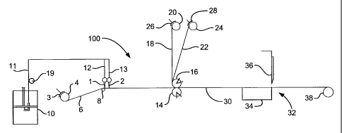
Referring to Figure 1, there is shown schematically,
a system 100 according to the present invention for
applying glue in a desired pattern to a screen or screens
(or mesh or meshes) and can be used to produce any screen
disclosed herein or in any other of our PCT Publications,
that employs glue or adhesive between two or more layers
of screen(s) and/or mesh (es) .
Hot glue for application to screen(s) or mesh(es) or
combination thereof is supplied to nozzles 1, 2 from a
glue apparatus 10 through lines 11, 12, and 13. Either
of the nozzles may be omitted; or, more than two nozzles
may be used. The line 11 may be a heated line or a
heated hose heated by optional heater apparatus 19. Any
suitable known glue system may be used, including but not
CA 02392481 2007-10-30
- 8 -
limited to, hot glue systems which heat glue and then
pump it to a flow line. In one particular aspect
BulkMeter Applicators Model 5530, 5540, or 5506
commercially available from the Nordson Corporation of
Amherst, Ohio may be used in systems according to the
present invention (for example, for the apparatus 10 in
the system of Figure 1).
From a rotating roll 4 a sheet of screen or mesh 6
is unwound from the roll 4 and moved over an idler roller
8 to a position beneath the nozzles 1, 2 (or only one of
them when one of them is omitted). A brake 3 provides
tension on the screen or mesh 6 as it is pulled from the
roll 4. In certain aspects a roll of woven wire (screen
or mesh) between for example, 30m to 90m (100 to 300
feet) in length is rolled from the roll 4.
The screen or mesh 6 with a glue pattern deposited
thereon (any glue disclosed herein) moves between a
rotating stationary (with respect to vertical position)
roller 14 and rotating adjustable (with respect to
vertical position) roller 16. In certain aspects it is
preferred that the rollers 8, 14 are as close together as
possible. Any roller in the system or roll can be a
"driven" roller or roll, for example, powered by a motor
with appropriate gearing, shafts, interconnections, etc.,
to pull the woven wire (screen or mesh) from the roll 4.
In one particular aspect the roll 38 is a driven roll
that pulls the woven wire from the roll 4. The driven
roll 4 (or other driven roll or roller) can be rotated
continuously as glue is deposited on the screen or mesh;
or it can be drivingly rotated at intervals so that a
desired portion of a layer of wire mesh is positioned
beneath the nozzle(s) for glue pattern deposition.
Following application of the desired glue pattern to the
portion of the layer, the roll is again activated to
remove the portion with the glue pattern and to position
CA 02392481 2007-10-30
- 9 -
a new un-treated portion beneath the nozzle(s).
A second screen or mesh sheet 18 unwound from a
rotating roll 20 and, optionally, a third screen or mesh
sheet 22 unwound from a rotating roll 24, are also fed
between the rollers 14, 16 between which all the sheets
are pressed together. Brakes 26, 28 provide tension as
desired on the rolls 20, 24, respectively. Pressure on
the combination of sheets may be adjusted by adjusting
the vertical position of the adjustable roller 16. It is
within the scope of this invention to make a screen with
any desired number of layers, or sheets of screening
material (screen and/or mesh), including, but not limited
to a final screen product with two, three, four, five or
more layers.
In certain aspects the adjustable roller 16 is
positioned so that the sheets moving between the rollers
14 and 16 are bound together and part of the sheets are
encapsulated in glue of the glue pattern. Either or both
of the rollers 14, 16 can be a driven roller, for
example, driven with a motor, to pull the various sheets
between the rollers from their respective rolls. The
rollers may act as heat sinks removing heat from the glue
and/or cooling fluid may be circulated through one or
both rollers to cool the glue.
Optionally a screen and/or mesh combination 30
exiting from between the rollers 14, 16 may be cut to
length as desired with a shear apparatus 32 including a
support 34 and a shear device 36; or the combination 30
may be wound onto a roll 38.
In one particular aspect the sheet 6 is a layer of
relatively coarse wire mesh (and, in certain embodiments,
may be any coarse wire mesh disclosed herein) ; the sheet
18 is a layer of medium wire mesh (and may be any medium
wire mesh, for example,, but not limited, between 20 mesh
and 250 mesh disclosed herein); and the sheet 22 is a
CA 02392481 2007-10-30
- 10 -
layer of fine wire mesh (and may be any fine wire mesh
disclosed herein).
Any suitable known movement mechanism may be used to
move the nozzle or nozzles above a layer of screen or
mesh. One movement mechanism 40 is shown schematically
in Figure 2A and includes a first bar 41 at right angles
to a second bar 42 on which is movably mounted a glue
nozzle 44. The second bar 42 has a finger 45 that
projects down into a guide channel 43 of the first bar
41. As the second bar 42 moves with respect to the first
bar 41 the finger 45 moves in the guide channel 43 to
guide the movement of the second bar 42. The glue nozzle
44 moves along the second bar 42, for example, a shaft 46
projecting down from a knob 47 moves in an elongated
opening 48 to guide movement of the glue nozzle 44 with
respect to the second bar 42. Appropriate movement of
the second bar 42 with respect to the first bar 41 and
simultaneously of the glue nozzle 44 with respect to the
second bar 42 makes possible the application of a glue
bead in a desired pattern on a screen or mesh below the
nozzle 44. One, two, three, four or more glue nozzles
may be movably mounted on the second bar; or a plurality
of glue nozzles each with its own movement mechanism may
be used. Alternatively, and for any embodiment disclosed
herein, the layer or layers of screening material may be
moved below fixed nozzle(s) to produce a desired glue
pattern thereon. For example a portion of a roll of mesh
to have a glue pattern deposited thereon is placed on a
movable and inextendable table or other suitable support
with a nozzle or nozzles mounted thereabove.
Figure 2B shows a system 80 according to the present
invention with two nozzle movement mechanisms 81, 82
(like the mechanism of Figure 2A) each with a nozzle AA
and a nozzle BB respectively. In one method according to
the present invention, nozzle AA is moved from the
CA 02392481 2007-10-30
- 11 -
indicated position la to a new position 2a, depositing a
first glue bead on the screen or mesh 6 (like that in
Figure 1) along a path from position la to position 2a.
The nozzle BB is moved (and may be moved before the
nozzle AA is moved) from its initial position 4a to a new
position 5a, depositing as it moves a glue bead on the
screen or mesh 6 along the path from position 4 to
position 5. The screen or mesh 6 is then moved a
predetermined increment (to the right or to the left as
viewed in Figure 2B) and nozzle AA is moved back to
position la (depositing a new glue bead on the screen or
mesh as it moves, the new glue bead spaced-apart from the
first glue bead) and, similarly, the nozzle BB moves back
to position 4a depositing a corresponding glue bead.
Alternatively, both nozzles may move on to a subsequent
position (instead of moving back to positions la and 4a,
respectively) ; position 3a for nozzle AA and position 6a
for nozzle BB. It is within the scope of this invention
for the nozzles to then move back to their initial
positions following a movement or indexing of the screen
or mesh, depositing a new glue bead when traversing the
screen or mesh in the reverse direction (or not
depositing a glue bead). The position la to 2a to 3a
(nozzle AA) and position 4a to 5a to 6a (nozzle BB)
movements can then be repeated. Alternatively only one
of the nozzles may be used, moving to a second position
and, optionally, on to a third position, and, optionally,
then back to the second and then the first position.
Although the nozzle paths shown in Figure 2B are
substantially straight it is within the scope of this
invention for either or both paths to be curved, zig zag,
or wavy as viewed from above.
Typically a deposited glue bead has a width as
viewed from above of between 0.12cm and 0.24cm (3/64ths
and 3/32nds of an inch), and, in one particular aspect
CA 02392481 2007-10-30
- 12 -
this width is about 0.16cm (1/16 inch) In certain
aspects the distance of a glue nozzle above a layer of
screen or mesh is between 0.95cm to 1.6cm (3/8 inch to
5/8 inch) and the nozzle (or nozzles) are moved at a rate
of 1.3 to 2 metres per min (4 to 6 feet per minute) (or
the layer of screen or mesh is moved below a stationary
nozzle or nozzles at this rate).
Figure 3 shows a system 50 according to the present
invention like the system of Figure 1 in which the
nozzles 1, 2 are initially positioned on opposite sides
of a stationary portion of a layer of screen or mesh 6.
Nozzle 1 moves from a position A to a position B laying
down a glue bead X and then reverses direction and moves
from position B to position C laying down a glue bead Y.
Simultaneously the nozzle 2 moves from a position D to a
position E laying down a glue bead P and then reverses
direction and moves to a position F laying down a glue
bead Q. As these movements of the nozzles are repeated a
pattern R of glue is deposited on the screen or mesh 6.
When the nozzles have covered the desired portion of the
layer of screen or mesh with the desired pattern, the
layer is moved beneath the nozzles so that they are then
positioned above a new layer portion to which the pattern
is to be applied. Once the new portion is correctly
positioned, the nozzles begin applying the glue pattern
as before. Alternatively, the screen or mesh also moves
below the nozzles as the glue is being dispensed.
Figure 4 shows a system 60 according to the present
invention like the system of Figure 1 with a single glue
nozzle 61 that dispenses a glue bead onto the screen or
mesh 6 and moves from a position G, to a position H, then
to a position I, to a position J, and then to a position
K. By repeating this cycle of movement a pattern S of
glue is applied to the screen or mesh 6. When the
desired pattern has been applied to a portion of the
CA 02392481 2007-10-30
- 13 -
screen or mesh 6, the glue flow is (optionally) shut-off,
the screen or mesh 6 is moved beneath the nozzle 61 so
that glue may be applied to another portion of the screen
or mesh 6. Alternatively, the layer of screen or mesh 6
also is moved beneath the nozzle 61 as glue is being
applied thereto; or, in another aspect, following nozzle
movement (for example, from points G to H to I) the
screen or mesh is moved (for example, indexed a desired
distance) below the nozzle and then the nozzle is moved
in a reverse path (for example, from points I to J to K).
Figure 5 shows a system 70 according to the present
invention like the system of Figure 1 with a bank of glue
nozzles 72 and a glue nozzle 71. The bank of nozzles 72
applies a plurality of glue beads 73 to the screen or
mesh 6. The nozzle 71 moves above the screen or mesh 6
to apply a plurality of glue beads 74, producing a
pattern T of glue on the screen or mesh 6. Either the
bank of nozzles is moved with respect to the layer of
screen or mesh 6, or the layer is moved below the bank of
nozzles, or both. It is also possible to move the entire
bank of nozzles at an angle to the direction of movement
of the layer of screen or mesh 6. Also, a bank of
nozzles may be used on the side of the layer 6 instead of
a single nozzle like the nozzle 71.
Figures 6A to 6D show possible glue patterns that
may be applied by systems according to the present
invention (including, but not limited to, systems as in
Figure 2, Figure 2B and Figs. 3 - 5). These patterns can
be achieved by appropriate control of rate of movement of
the screen or mesh and/or by the rate and/or direction of
travel of the nozzle(s). In Figures 6A to 6D, angle
measurements are in degrees (either " " or "deg"), length
measurements are in inches ("inches" or "in" or a number,
for example, Figure 6A "1.38" is 1.38 inches) and area
measurements ("sq. in.") are in square inches. It is
CA 02392481 2007-10-30
- 14 -
also within the scope of this invention: to substitute
any patterning roller described herein for any bank of
nozzles (for example, but not limited to the bank of
nozzles in the system 70); to substitute any patterning
roller described herein for any nozzle in any system in
Figures 1 to 5; and to use a roller to deposit any glue
bead deposited by any nozzle in any system in Figures 1
to 5.
As with other systems described herein, the cooling
of hot glue deposited by a nozzle or nozzles can be
effected by the use of one or more fans or coolers and/or
by circulating cooling fluid through one or more rollers
and/or rolls that contact and/or are adjacent hot glue.