Note: Descriptions are shown in the official language in which they were submitted.
i
CA 02392522 2002-05-22
HINGE ASSEMBLY
Technical Field
This invention relates to a hinge assembly which is suited to be used
for a foldable cellular telephone or the like.
Background Art
In general, a foldable cellular telephone includes, as shown in FIGS. 18
and 19, a transmission section A and a reception section B. The transmission
section A and the reception section B are turnably connected through a hinge
assembly (not shown) for turning between a non-talk position where the
transmission section A and the reception section B are abutted with each
other as indicated by a solid line of FIG. 18 and a talk position as indicated
by a solid line of FIG. 19. Moreover, when the angle formed between the
transmission section A and the reception section B is smaller than a , the
transmission section A and the reception section B are turned into a non-talk
position by bias means built in the hinge assembly and held in that position.
When the angle formed between the transmission section A and the reception
section B is brought to be larger than a predetermined angle /3 , the
transmission section A and the reception section B are turned into the talk
position by bias means and held in that position.
As shown in FIG. 20, the hinge assembly includes a pair of abutment
plates (abutment members) C,D arranged in mutually opposing relation and
bias means (not shown) for biasing the paired abutment plates C,D towards
each other. The pair abutment plates C,D are non-turnably connected to the
transmission section A and the reception section B, respectively.
i
CA 02392522 2002-05-22
2
Therefore, the abutment plates C,D are relatively turned as the transmission
section A and the reception section B are turned.
The abutment plate C has a pair of projections C1, C1 which are
formed on its opposing surface with respect to the abutment plate D and
which are arranged 180 degrees away from each other in the circumferential
direction. The remaining abutment plate D also has a pair of recesses D1, D1,
which are formed on its opposing surface with respect to the abutment plate
C and which are arranged 180 degrees away from each other in the
circumferential direction. The projection C1 and the recess D1 retain the
transmission section A and the reception section B in a non-talk position or
in
a talk position with the help of the biasing force of the bias means.
Specifically, as shown in FIG. 21, the projection C1 and the recess D1
are arcuate in section. When the transmission section A and the reception
section B are in the non-talk position, the projection C1 and the recess D1
are,
as shown in FIG. 21(A), abutted with each other at areas which are slightly
circumferentially away from their centers. Owing to this arrangement, the
biasing force of the bias means is converted into a rotational biasing force
(rotation biasing force for turning the abutment plate D in a direction
opposite to the arrowed direction) for turning the abutment plate C in the
arrowed direction. By this rotational biasing force, the transmission section
A and the reception section B are held in the non-talk position. As shown in
FIG. 21(B), when the angle formed between the transmission section A and
the reception section B is a or less, an area which is slightly away from the
central part of the projection C1 contact one end portion of the recess D1. By
this, the abutment plate C is biased in the arrowed direction of FIG. 21(B)
and the transmission section A an the reception section B are turned in the
non-talk position. When the angle formed between the transmission section
A and the reception section B is /3 or more, the projection C1 and the recess
D1 are brought into a symmetrical state with respect to the state shown in
fl
CA 02392522 2002-05-22
3
FIG. 2I(B). Accordingly, the abutment plate C is biased in a direction
opposite to the arrowed direction and the transmission section A and the
reception section B are turned as far as to the talk position. When the
transmission section A and the reception section B are located in the talk
position, the projection C1 and the recess D1 are press-contacted at their
central areas with each other as shown in FIG. 21(C). In that connection, the
biasing force of the bias means merely urges the projection C1 against the
bottom surface of the recess D1 and is never converted into a rotational
biasing force. However, when the abutment members C,D are turned into
either one direction from the position (hereinafter referred to as the
"neutral
position") shown in FIG. 21(C), the biasing force of the bias means is
converted into a rotational biasing force and causes the abutment members
C,D to return into the neutral position. Accordingly, the transmission section
A and the reception section B are held in the talk position.
In the above hinge assembly, when the abutment members C,D are
turned, even if slightly, from the neutral position, the biasing force of the
bias
means should, theoretically, be converted into a rotational biasing force for
returning the abutment members C,D to the neutral position. Actually,
however, since the nearby areas (central areas of the projection C1 and the
recess D1 in the circumferential direction of the abutment members C,D) of
the contact points between the projection C1 and the recess D1 in the neutral
position are generally orthogonal to the biasing direction of the bias means,
the biasing force of the bias means is hardly converted into the rotational
biasing force in the position where the abutment members C,D are slightly
turned from the neutral position, and the abutment members C,D are not
returned to the neutral position. For this reason, the transmission section A
and the reception section B are not positioned in the talk position with a
decent degree of modesty. This results in a problem that play is liable to
occur.
si
CA 02392522 2002-05-22
4
Disclosure of the Invention
In order to solve the above problem, the features of the present
invention reside in a hinge assembly comprising a pair of abutment members
arranged in mutually opposing relation and capable of making relative
rotation, and bias means for biasing the pair of abutment members, so as to
be press contacted with each other, one of the pair of abutment members
having a projection formed on an opposing surface thereof and extending
radially of the abutment member, the other abutment member having a
recess formed on an opposing surface thereof and allowing the projection to
be brought therein and thereout in accordance with the relative rotation of
the their abutment members, when the projection is brought into the recess,
the pair of abutment members being forcibly turned to a neutral position,
side view where central areas of the projection and recess in a
circumferential direction of the abutment members are generally coincident
with each other,
the hinge assembly being characterized in that when the pair of abutment
members are turned into the neutral position, the projection being brought
into contact with the recess at opposite side portions in a circumferential
direction of the member.
It is preferred that an outer surface of the projection is defined by an
arcuate surface extending in a radial direction of the abutment member.
It is also preferred that opposite side surfaces of the recess in the
circumferential direction of the abutment member is defined by an outwardly
projecting arcuate surface.
Brief Description of Drawings
FIG. 1 is a front view showing one mode for carrying out the present
invention.
CA 02392522 2002-05-22
FIG. 2 is an illustration as viewed in a direction as indicated by an
arrow X of FIG. 1.
FIG. 3 is an illustration as viewed in a direction as indicated by an
arrow Y of FIG. 1.
FIG. 4 is an illustration as viewed in a direction as indicated by an
arrow Z of FIG. 1.
FIG. 5 is a front sectional view of the above mode.
FIG. 6 is an ezploded perspective view of the above mode.
FIG. 7 is an illustration showing a first fixing member used in the
above mode, FIG. 7(A) is a front view, FIG. 7(B) is a right side view, FIG.
7(C)
is a plan view, FIG. 7(D) is a lower surface view, and FIG. 7(E) is a front
sectional view thereof.
FIG. 8 is an illustration showing a second fixing member used in the
above mode, FIG. 8(A) is a front view, FIG. 8(B) is a right side view, FIG.
8(C)
is a plan view, FIG. 8(D) is a lower surface view, and FIG. 8(E) is a side
sectional view thereof.
FIG. 9 is an illustration showing a movable disc used in the above
mode, FIG. 9(A) is a front view, FIG. 9(B) is a right side view, FIG. 9(C) is
a
plan view, FIG. 9(D) is a lower surface view, and FIG. 9(E) is a front
sectional
view thereof.
FIG. 10 is an illustration showing a fined disc used in the above mode.
FIG. 10(A) is a front view, FIG. 10(B) is a right side view, FIG. 10(C) is a
front sectional view, FIG. 10(D) is a lower surface view thereof.
FIG. 11 is a plan view showing a relation between a recess and a
projection when the movable disc and the fixed disc are returned into the
neutral position.
FIG. 12 is a sectional view taken on line X-X of FIG. 11.
FIG. 13 is a sectional view taken on line Y-Y of FIG. 11.
si
CA 02392522 2002-05-22
6
FIG. 14 is a plan view showing a relation between a recess and a
projection when the movable disc and the fixed disc are slightly turned from
the neutral position.
FIG. 15 is a view showing a contact range of a projection with respect
to a recess according to the present invention.
FIG. 16 is a view showing a contact range of a projection with respect
to a recess according to the prior art.
FIG. 1? is a sectional view, like FIG. 12, showing another mode for
carrying out the present invention.
FIG. 18 is a view showing one example of a cellular telephone having a
hinge assembly according to the present invention, in which the transmission
section and the reception section are turned into the non-talk position.
FIG. 19 is a view showing one example of the above cellular telephone,
in which the transmission section and the reception section are turned into
the talk position.
FIG. 20 is a perspective view showing a pair of abutment plates of the
conventional hinge assembly.
FIG. 21 is an enlarged sectional view showing a relation between the
projection and recess formed on the pair of abutment plates shown in FIG. 20,
FIG. 21(A) shows a state in which the transmission section and the reception
section are turned in the non-talk position, FIG. 21(B) shows a state in which
the transmission section and the reception section are turned by an angle a
from the non-talk position, and FIG. 21(C) shows a state in which the
transmission section and the reception section are turned into the talk
position.
Best Mode for Carrying Out the Invention
One mode for carrying out the invention, in which the invention is
incorporated with a hinge assembly used for a foldable cellular telephone,
a
CA 02392522 2002-05-22
7
will be described herein after with reference to FIGS. 1 through 16. It should
be noted, however, the present invention can be applied to other hinge
assemblies than a hinge assembly used for a foldable cellular telephone,
inasmuch as those hinge assemblies are used for turnably connecting two
turning members.
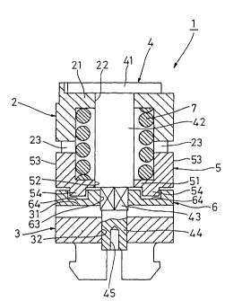
As shown in FIGS. 1 through 6, a hinge assembly 1 includes first and
second fixed members 2,3, a hinge pine 4, a movable disc (abutment member)
5, a fixed disc (abutment member) 6 and a coiled spring (bias means) 7.
Those components 2 through 7 are arranged with their ages aligned.
As shown in FIGS. 1 through 6 and FIG. ?, the first fined member 2
has a bottom portion 21 at one end portion thereof and is open at the other
end portion, thus exhibiting a cylindrical configuration with a bottom. The
first fixed member 2 is non-turnably connected to one of the transmission
section A and the reception section B with its axis aligned with the rotation
aces of the transmission section A and the reception section B. A through
hole 22 is formed in a central area of the bottom portion 21. A pair of guide
grooves 23, 23 axially extending from the open end face is formed in the open
end portion aide of a peripheral wall portion of the first fixed member 2, The
pair of guide grooves 23, 23 are 180 degrees away from each other in the
circumferential direction.
The second fazed member 3 is non-turnably connected to the other of
the transmission section A and the reception section B in such a manner as to
be in opposing relation to the first fined member. As shown in FIGS. 1
through 6 and FIG. 8, a receiving recess 31 is formed in an opposing surface
of the second fined member 3 with respect to the first fined member 2. A
through hole 32 is formed in a central area of the first fined member 2.
As shown in FIG. fi, the hinge pin 4 includes a head portion 41, an
enlarged diameter portion 42, a sectionally hexagonal fined portion 43, and a
reduced diameter portion 44, which are all arranged in order from one end
i
CA 02392522 2002-05-22
g
portion thereof towards the other end portion. Those components 41 through
44 are formed such that their azes are aligned with one another. The
enlarged diameter portion 42 is inserted into the through hole 22 until the
head portion 41 hits the bottom portion 21 of the first fined member 2. The
enlarged diameter portion 42 is turnably fitted to the through hole 22. The
reduced diameter portion 44 is inserted into the through hole 32 of the second
fined member 3. After insertion, the second fined member 3 is positionally
fined to the reduced diameter portion 44 by caulking the reduced diameter
portion 44 utilizing a caulking hole 45 formed in a distal end face of the
reduced diameter portion 45 so that the reduced diameter portion 44 is
enlarged in diameter. The outside diameter of the reduced diameter portion
44 has a generally same diameter as a circle inscribing the hezagon which
constitutes the fined portion 43.
As shown in FIGS. 1 through 6 and FIG. 9, the movable disc 5 includes
a disc-like substrate portion 51. This substrate portion 51 is axially movably
inserted into the end portion on the open end portion side of the first fined
member 2. A through hole 52, into which the enlarged diameter portion 42 of
the hinge pin 4 is relatively turnably and relatively movably inserted, is
formed in a central area of the substrate portion 51. A pair of guide portions
53, 53 are formed on the one and the other side portions of the substrate
portion 51. The movable disc 5 is axially movably but non-turnably
connected to the first fined member 2 by slidingly movably fitting the pair of
guide portion 53, 53 to the guide grooves 23, 23 of the first fi$ed member 2.
Between the substrate portion 51 of the movable disc 5 and the bottom
portion 21 of the first fi$ed member 2, the coiled spring 7 is disposed in its
compressed state. The movable disc 5 is biased towards the second fixed
member 3 side by the coiled spring 7.
As shown in FIGS. 1 through 6 and FIG. 10, the fixed disc 6 includes a
disc-like substrate portion 61 and a ridge 62 formed on a lower surface
i
CA 02392522 2002-05-22
9
(surface on the reverse side of the movable disc 5 side) of the substrate
portion 61. The fined disc. 6 is, as a whole, formed in a generally same
configuration as the receiving recess 31. The fixed disc 6 is fitted to the
receiving recess 31, thereby the fined disc 6 is non-turnably connected to the
second fined member 3. A through-hole 63 is formed in a central area of the
fined disc 6. This through hole 63 has an inside diameter generally equal to
the outside diameter of the reduced diameter portion 44 of the hinge pin 4. A
sectionally hexagonal fined portion 43 is fixedly press fitted to the through
hole 63. By this, the fined disc 6 and the second fixed member 3 are
connected to the hinge pin 4 such that they are rotated in unison. This hinge
pin 4 is not absolutely necessarily connected to the second fined member 3
and the fined disc 6 such that they are rotated in unison. The hinge pin 4
may be connected to the first fined member 2 and the movable disc 5 such
that they are rotated in unison. Alternatively, the hinge pin 4 may be
connected to the first and second fined members 2,3, the movable disc 5 and
the fixed disc 6 so that they can all rotate.
The fined disc 6 is received by the second fixed member 3 in the
direction towards the second fined member 3 side from the first fined member
2 side. Accordingly, the opposing surface 5a of the movable disc 5 is pressed
against the opposing surface 6a of the fined disc 6 by the coiled spring 7. As
shown in FIGS. 5, 6 and 9, a pair of projections 54, 54 are formed on the
opposing surface 5a of the movable disc 5 such that the projections 54, 54 are
arranged 180 degrees away from each other on a circumference about the
axis of the movable disc 5. On the other hand, a pair of recesses 64, 64 are
formed on the opening surface 6a of the fixed dish such that the recesses 64,
64 are 180 degrees away from each other in the circumferential direction, as
shown in FIGS. 5, 6 and 10. The recess 64 is arranged on the same
circumference as the projection 54. Moreover, the length of the recess 64 in
CA 02392522 2002-05-22
1
the radial direction of the discs 5, 6 is longer than that of the projection
54 in
that direction.
As shown in FIGS. 11 and 12, the projection 54 is extended in the
radial direction of the movable disc 5 with a predetermined width. The
center line Ll in the width direction is orthogonal to the axis of the movable
disc 5. The outer surface of the projection 54 is defined by an outwardly
projecting arcuate surface, and the center line of this arcuate surface is,
when
viewed in the axial direction of the movable disc 5, aligned with the center
line L1. Accordingly, the projection 54 is symmetrical with respect to the
center line Ll. Its sectional configuration orthogonal to the center line Ll
is
same , in any section. As a result, the projection 54 exhibits a square
configuration, in which crossing ridge lines 54a, 54a between the projection
54 and the opposing surface 5a of the movable disc 5 is, when viewed in the
axial direction of the movable disc 5, parallel to the center line L1.
The recess 64 comprises an inner recess fi5 formed on the inner side in
the radial direction of the fixed disc 6 and an outer recess 66 formed on the
outer side in the radial direction.
The inner recess 65 is extended in the radial direction of the fixed disc
6 with a predetermined width. The center line L2 in its width direction is
orthogonal to the axis of the fixed disc 6. The sectional configuration
orthogonal to the center line L2 of the inner recess 65 is same in any
section.
Moreover, the inner recess 65 is symmetric with respect to the center line L2.
Opposite side surfaces 65a, 65a (opposite side surfaces located in the
circumferential direction of the fixed disc 6) of the inner recess 65 are
defined
by an outwardly projecting convexly curved surface. Especially, in this mode
for carrying out the present invention, they are defined by an arcuate surface
and the center of the arcuate surface is parallel to the center line L2.
Moreover, one end portion of this arcuate surface is in contact with the
opposing surface 6a.
CA 02392522 2002-05-22
11
On the other hand, the outer recess 66 is formed in a sector-like
configuration which is gradually increased in width towards the outer
periphery side from the inner periphery side of the fixed disc 6 when viewed
in the axial direction of the fixed disc 6. The width of. the inner periphery
side end portion of the outer recess 66 is equal to the width of the inner
recess 65. The outer recess 66 is also symmetric with respect to the center
line L2. Its side surface 66a is defined by an arcuate surface having a
generally same radius of curvature as the arcuate surface which defines the
side surface 65a. One end portion of the arcuate surface which defines the
side surface 66a is also in contact with the opposing surface 6a. The arcuate
surface which defines the side surface 66a and the arcuate surface which
defines the side surface 65a are crossed with each other without leaving any
step therebetween. The crossing ridge lines are denoted by reference
numeric characters L3, L4 of FIG. 11. The line L5 connecting contact areas
between the side surface 66a and the opposing surface 6a is orthogonal to the
axis of the fixed disc 6. Accordingly, the center line of the arcuate surface
which defines the side surface 66a, is parallel to the line L5 but never
crossed
with the axis of the fined disc 6. The center line of the arcuate surface
which
defines the side surface 66a may be orthogonal to the axis of the fixed disc
6.
In that case, the line L5 is not orthogonal to the axis of the fixed disc 6.
The relation between the projection 54 and the inner and outer
recesses 65, 66 will now be described. As shown in FIG. 11, when the
transmission section A and the reception section B of the cellular telephone
are located in the talk position, the center lines Ll, L2 are aligned with
each
other when viewed in the direction of the axes of the discs 5, 6. The position
of the movable disc 5 and the fixed disc 6 at that time is the neutral
position.
In the state in which the movable disc 5 and the fixed disc 6 are
located in the neutral position, the central area of the projection 54 is, as
shown in FIG. 12, away from the bottom surface 65b of the inner recess 65
CA 02392522 2002-05-22
12
and only the opposite side portions of the projection 54 are in contact with
the
opposite side surfaces 65a, 65a of the inner recess 65. Moreover, since the
center line L1 of the projection 54 and the center line of the arcuate surface
which defines the side surface 65a of the inner recess fi are parallel to each
other, the projection 54 and the side surface 65a are in line contact
(substantially in surface contact) as indicated by hatching of FIG. 11. On the
other hand, since the outer recess fifi is increased in width as it goes
outward
away from the inner recess 65, the projection 54 is, as shown in FIG. 13, is
away from not only the side surface 66a of the outer recess 66 but also any
surface which defines the outer recess 66.
When the two discs 5, 6 are turned from the neutral position of FIGS.
11 and 12 within a range of a smaller angle than an angle a 1, the projection
54 is brought into contact, as indicated by hatching of FIG. 14, with an end
portion of the outer periphery side of the side surface 65a of the inner
recess
65 and an end portion of the inner side of the side surface fi6a of the outer
recess fifi. It should be noted, however, that when the transmission section A
and the reception section B are turned from the neutral position by an angle
a , the center line L2 and the line L5 are aligned with each other when
viewed in plan view. As a result, the central area of the projection 54 is
brought into line contact with the side surface 65a (opposing surface 6a) on
the line L5.
When the angle formed between the transmission section A and the
reception section B is brought to be larger than /3 , a state symmetric with
the state of FIG. 14 is realized.
In the hinge assembly 1 thus constructed, since the projection 54 and
the inner recess 65 of the recess fi4 are contacted with each other at two
areas away in the circumferential direction of the discs 5, 6 when the
transmission section A and the reception section B are turned into the talk
position and the movable disc 5 and the fined disc 6 are brought into the
fl
CA 02392522 2002-05-22
13
neutral position, the movable disc 5 and the fined disc 6 can be positionally
fined with a decent degree of modesty. Accordingly, the transmission section
A and the reception section B can surely be prevented from getting clattering
in the talk position.
Moreover, in the hinge assembly 1 according to this mode for carrying
out the present invention, since the recess 64 comprises a square inner recess
65 and a sector-like outer recess 66, the projection 54 and the recess 64 can
be prevented from getting worn off soon. That is, if the inner recess 65
should be eztended towards the outer periphery side and the entire recess 64
should comprise of the inner recess 65, the projection 54 and the side surface
of the recess 64 would contact only at the end portion on the outer periphery
side when the movable disc 5 should be moved, even slightly, from the
neutral position with respect to the fined disc 6. For this reason, the
projection 54 and the recess 64 are readily worn off soon.
On the other hand, in the hinge assembly 1 in which the recess 64
comprises the square inner recess 65 and the sector-like outer recess 66,
when the movable disc 5 is turned from the neutral position, an intermediate
portion of the projection 54 in the radial direction of the movable disc 5 is
brought into contact at an end portion Q on the outer periphery side with the
side surface 65a of the inner recess 65 as indicated by hatching of FIG. 14.
The same is true with respect to the case where the entire recess 64
comprises only the inner recess 65. However, in this hinge assemblyl, the
recess 64 includes the outer recess 66, and the intermediate area of the
projection 54 is contacted with the side surface 66a of the outer recess 66
also
at its inner end portion R. Accordingly, the contact area between the
projection 54 and the recess 64 is increased twice. Hence, the projection 54
and the recess 64 can be prevented from getting worn off soon.
As apparent from FIGS. 15 and 16, in the case where the side surfaces
65a, 66a of the recess 64 comprises the outwardly projected arcuate surface
i
CA 02392522 2002-05-22
14
as in this hinge assembly 1, the length of the contact area (area indicated by
double hatching of FIG. 15) of the projection 54 with respect to the side
surfaces 65a, 66a of the projection 54 when the movable disc 5 and the fined
disc 6 are turned, is larger than the length of the contact area (area
indicated
by double hatching of FIG. 16) in the case where the bottom surface 64ay
which defines the recess 64, comprises a concavely curved surface. By this,
the projection 54 can more effectively be prevented from getting off soon.
It should be noted that the present invention should never be limited
to the above-mentioned mode for carrying out the present invention. Instead,
many changes and modifications can be made in accordance with necessity.
For ezample, in the above-mentioned mode for carrying out the present
invention, although the recess 64 comprises the inner recess 65 and the outer
recess 66, it is also accepted that the inner recess 65 is eztended outward at
the outer recess and the entire recess 64 comprises the inner recess 65.
As shown in FIG.17, it is also accepted that the surface, which defines
the recess 64, comprises the concavely curved surface 64a at the width-wise
central area and concavely curved surface 64b on the opposite sides. In this
case, the concavely curved surface 64a comprises an arcuate surface having a
smaller radius of curvature than the arcuate surface which defines the
projection 54, so that the projection 54 can contact the recess 64 at two
areas
which are away from each other in the circumferential direction when the
movable disc 5 and the fixed disc 6 are turned into the neutral position. The
concavely curved surface 64b comprises an arcuate surface having a larger
radius of curvature than the arcuate surface which defines the projection 54.
With respect to the construction in which the recess 64 comprises only one
concavely curved surface 64a on the center side and two concavely curved
surface 64b on the width-wise opposite sides, the same is applicable to the
recesses 65, 66 in which the recess 64 is divided into the inner recess 65 and
the outer recess 66.
!I
CA 02392522 2002-05-22
Moreover, in the above-mentioned mode for carrying out the present
invention, one pair of projections 54 and one pair of recesses 64 are arranged
in such a manner as to be 180 degrees away from each other in the
circumferential direction. It is also accepted, as in Japanese Patent
Application Unexamined Publication No. H10-317779 (especially FIG. 12),
that a pair of projections 54 are arranged at an angle less than 180 degrees,
for example, about 160 degrees, and three recesses 64 are formed and
arranged in a pattern of "Y".
Industrial Applicability
A hinge assembly according to the present invention can be used as a
hinge assembly for turnably connecting two goods, such as, a main body and
a cover of a cellular telephone or the like.