Note: Descriptions are shown in the official language in which they were submitted.
CA 02392601 2002-05-23
WO 01/41504 PCT/US00/32383
-1-
DESCRIPTION
Method for Deriving at Least Three Audio Signals
from Two Input Audio Signals
Technical Field
The invention relates to audio signal processing. In particular, the invention
relates to "multidirectional" (or "multichannel") audio decoding using an
"adaptive" (or
"active") audio matrix method that derives three or more audio signal streams
(or
"signals" or "channels") from a pair of audio input signal streams (or
"signals" or
"channels"). The invention is useful for recovering audio signals in which
each signal
is associated with a direction and was combined into a fewer number of signals
by an
encoding matrix. Although the invention is described in terms of such a
deliberate
matrix encoding, it should be understood that the invention need not be used
with any
particular matrix encoding and is also useful for generating pleasing
directional effects
from material originally recorded for two-channel reproduction.
Background Art
Audio matrix encoding and decoding is well known in the prior art. For
example, in so-called "4-2-4" audio matrix encoding and decoding, four source
signals,
typically associated with four cardinal directions (such as, for example,
left, center,
right and surround or left front, right front, left back and right back) are
amplitude-
phase matrix encoded into two signals. The two signals are transmitted or
stored and
then decoded by an amplitude-phase matrix decoder in order to recover
approximations
of the original four source signals. The decoded signals are approximations
because
matrix decoders suffer the well-known disadvantage of crosstalk among the
decoded
audio signals. Ideally, the decoded signals should be identical to the source
signals,
with infinite separation among the signals. However, the inherent crosstalk in
matrix
decoders results in only 3 dB separation between signals associated with
adjacent
CA 02392601 2010-09-24
73221-59
2
directions. An audio matrix in which the matrix characteristics do not vary is
known in
the art as a "passive" matrix.
In order to overcome the problem of crosstalk in matrix decoders, it is known
in
the prior art to adaptively vary the decoding matrix characteristics in order
to improve
separation among the decoded signals and more closely approximate the source
signals.
One well known example of such an active matrix decoder is the Dolby Pro Logic
decoder, described in U.S. Patent 4,799,260. The '260 patent cites a number of
patents that
are prior art to it, many of them describing various other types of adaptive
matrix
decoders. Other prior art patents include patents by the present inventor,
including
U.S. Patents 5,625,696; 5,644,640; 5,504,819; 5,428,687; and 5,172,415.
Although prior art adaptive matrix decoders are intended to reduce crosstalk
in
the reproduced signals and more closely replicate the source signals, the
prior art has
done so in ways, many of which being complex and cumbersome, that fail to
recognize
desirable relationships among intermediate signals in the decoder that may be
used to
simplify the decoder and to improve the decoder's accuracy.
Accordingly, the present invention is directed to methods and apparatus that
recognize and employ heretofore unappreciated relationships among intermediate
signals
in adaptive matrix decoders. Exploitation of these relationships allows
undesired
crosstalk components to be cancelled easily, particularly by using automatic
self-
cancelling arrangements using negative feedback.
Disclosure of Invention
In accordance with a first aspect of the invention, the invention constitutes
a
method for deriving at least three audio output signals from two input audio
signals, in
which four audio signals are derived from the two input audio signals by a
passive
matrix that produces two pairs of audio signals in response to two audio
signals: a first
CA 02392601 2002-05-23
WO 01/41504 PCT/US00/32383
-3-
pair of derived audio signals representing directions lying on a first axis
(such as "left"
and "right" signals) and a second pair of derived audio signals representing
directions
lying on a second axis (such as "center" and "surround" signals), said first
and second
axes being substantially mutually orthogonal to each other. Each of the pairs
of derived
audio signals are processed to produce respective first and second pairs (the
left/right
and center/surround pairs, respectively) of intermediate audio signals such
that the
magnitudes of the relative amplitudes of the audio signals in each pair of
intermediate
audio signals are urged toward equality. A first output signal (such as the
left output
signal Laõ representing a first direction lying on the axis of the pair of
derived audio
signals (the left/right pair) from which the first pair (the left/right pair)
of intermediate
signals are produced, is produced at least by combining, with the same
polarity, at least
a component of each of the second pair (the center/surround pair) of
intermediate audio
signals. A second output signal (such as the right output signal Romõ)
representing a
second direction lying on the axis of the pair of derived audio signals (the
left/right
pair) from which the first pair (the left/right pair) of intermediate signals
are produced,
is produced at least by combining, with the opposite polarity, at least a
component of
each of the second pair (the center/surround pair) of intermediate audio
signals. A third
output signal (such as the center output signal Co", or the surround output
signal S.,)
representing a first direction lying on the axis of the pair (the
center/surround pair) of
derived audio signals from which the second pair (the center/surround pair) of
intermediate signals are produced, is produced at least by combining, with the
same
polarity or the opposite polarity, at least a component of each of the first
pair (the
left/right pair) of intermediate audio signals. Optionally, a fourth output
signal (such as
the surround output signal Ste, if the third output signal is the enter output
signal C.,,,, or
C0,,, if the third output signal is Ste,) representing a second direction
lying on the axis of
the pair (center/surround) of derived audio signals from which the second pair
(center/surround) of intermediate signals are produced, is produced at least
by
combining, with the opposite polarity, if the third output signal is produced
by
CA 02392601 2002-05-23
WO 01/41504 PCT/US00/32383
-4-
combining with the same polarity, or by combining with the same polarity, if
the third
output signal is produced by combining with the opposite polarity, at least a
component
of each of said first pair (the left/right pair) of intermediate audio
signals.
The heretofore unappreciated relationships among the decoded signals is that
by
urging toward equality the magnitudes of the intermediate audio signals in
each pair of
intermediate audio signals, undesired crosstalk components in the decoded
output
signals are substantially suppressed. The principle does not require complete
equality in
order to achieve substantial crosstalk cancellation. Such processing is
readily and
preferably implemented by the use of negative feedback arrangements that act
to cause
automatic cancellation of undesired crosstalk components.
The invention includes embodiments having equivalent topologies. In every
embodiment, as described above, intermediate signals are derived from a
passive matrix
operating on a pair of input signals and those intermediate signals are urged
toward
equality. In embodiments embodying a first topology, a cancellation component
of the
intermediate signals are combined with passive matrix signals (from the
passive matrix
operating on the input signals or otherwise) to produce output signals. In an
embodiment employing a second topology, pairs of the intermediate signals are
combined to output signals.
Other aspects of the present invention include the derivation of additional
control
signals for producing additional output signals.
It is a primary object of the invention to achieve a measurably and
perceptibly
high degree of crosstalk cancellation under a wide variety of input signal
conditions,
using circuitry with no special requirements for precision, and requiring no
unusual
complexity in the control path, both of which are found in the prior art.
It is another object of the invention to achieve such high performance with
simpler or lower cost circuitry than prior art circuits.
CA 02392601 2010-09-24
73221-59
4a
According to another aspect of the present invention, there is
provided a method for deriving at least three audio signals, each associated
with a
direction, from two input audio signals, comprising generating with a passive
matrix in response to said two input audio signals a plurality of passive
matrix
signals including two pairs of passive matrix audio signals, a first pair of
passive
matrix audio signals representing directions lying on a first axis and a
second pair
of passive matrix audio signals representing directions lying on a second
axis,
said first and second axes being substantially mutually orthogonal to each
other,
processing each of said pairs of passive matrix audio signals to produce
respective first and second pairs of intermediate audio signals such that the
magnitudes of the relative amplitudes of the audio signals in each pair of
intermediate audio signals are urged toward equality, deriving a plurality of
cancellation signals from said pairs of intermediate audio signals, producing
at
least three output signals by combining each of at least three passive matrix
audio
signals with two or more of said plurality of cancellation signals, the
cancellation
signals opposing each passive matrix audio signal such that the passive matrix
audio signal is substantially cancelled by the cancellation signals when said
input
audio signals represent signals associated with directions other than the
direction
represented by the passive matrix audio signal.
CA 02392601 2002-05-23
WO 01/41504 PCT/US00/32383
-5-
Brief Description of the Drawings
Figure 1 is a functional and schematic diagram of a prior art passive decoding
matrix useful in understanding the present invention.
Figure 2 is a functional and schematic diagram of a prior art active matrix
decoder useful in understanding the present invention in which variably scaled
versions
of a passive matrix' outputs are summed with the unaltered passive matrix'
outputs in
linear combiners.
Figure 3 is a functional and schematic diagram of a feedback-derived control
system according to the present invention for the left and right VCAs and the
sum and
difference VCAs of Figure 2 and for VCAs in other embodiments of the present
invention.
Figure 4 is a functional and schematic diagram showing an arrangement
according to the present invention equivalent to the combination of Figures 2
and 3 in
which the output combiners generate the passive matrix output signal
components in
response to the L, and RL input signals instead of receiving them from the
passive matrix
from which the cancellation components are derived.
Figure 5 is a functional and schematic diagram according to the present
invention showing an arrangement equivalent to the combination of Figures 2
and 3 and
Figure 4. In the Figure 5 configuration, the signals that are to be maintained
equal are
the signals applied to the output deriving combiners and to the feedback
circuits for
control of the VCAs; the outputs of the feedback circuits include the passive
matrix
components.
Figure 6 is a functional and schematic diagram according to the present
invention showing an arrangement equivalent to the arrangements of the
combination of
Figures 2 and 3, Figure 4 and Figure 5, in which the variable-gain-circuit
gain (1-g)
provided by a VCA and subtractor is replaced by a VCA whose gain varies in the
opposite direction of the VCAs in the VCA and subtractor configurations. In
this
embodiment, the passive matrix components are implicit. In the other
embodiments,
CA 02392601 2002-05-23
WO 01/41504 PCT/US00/32383
-6-
the passive matrix components are explicit.
Figure 7 is an idealized graph, plotting the left and right VCA gains g, and
g, of
the L,/R, feedback-derived control system (vertical axis) against the panning
angle a
(horizontal axis).
Figure 8 is an idealized graph, plotting the sum and difference VCA gains g',
and
ge of the sum/difference feedback-derived control system (vertical axis)
against the
panning angle a (horizontal axis).
Figure 9 is an idealized graph, plotting the left/right and the inverted
sum/difference control voltages for a scaling in which the maximum and minimum
values of control signals are + /-15 volts (vertical axis) against the panning
angle a
(horizontal axis).
Figure 10 is an idealized graph, plotting the lesser of the curves in Figure 9
(vertical axis) against the panning angle a (horizontal axis).
Figure 11 is an idealized graph, plotting the lesser of the curves in Figure 9
(vertical axis) against the panning angle a (horizontal axis) for the case in
which the
sum/difference voltage has been scaled by 0.8 prior to taking the lesser of
the curves.
Figure 12 is an idealized graph, plotting the left back and right back VCA
gains
g,b and g,b of the left-back/right-back feedback-derived control system
(vertical axis)
against the panning angle a (horizontal axis).
Figure 13 is a functional and schematic diagram of a portion of an active
matrix
decoder according to the present invention in which six outputs are obtained.
Figure 14 is a functional and schematic diagram showing the derivation of six
cancellation signals for use in a six output active matrix decoder such as
that of Figure
13.
Figure 15 is a schematic circuit diagram showing a practical circuit embodying
aspects of the present invention.
CA 02392601 2002-05-23
WO 01/41504 PCT/US00/32383
-7-
Best Mode for Carrying out the Invention
A passive decoding matrix is shown functionally and schematically in Figure 1.
The following equations relate the outputs to the inputs, L, and R, ("left
total" and "right
total"):
Laut=L, (Eqn. 1)
Rout=R, (Eqn. 2)
Coõt='/2 *(L,+R) (Eqn. 3)
Saõt='h*(Lt R) (Eqn. 4)
(The "*" symbol in these and other equations throughout this document
indicates
multiplication.)
The center output is the sum of the inputs, and the surround output is the
difference between the inputs. Both have, in addition, a scaling; this scaling
is
arbitrary, and is chosen to be 'h for the purpose of ease in explanation.
Other scaling
values are possible. The Cou, output is obtained by applying L, and R, with a
scale
factor of +'/2 to a linear combiner 2. The Soõt output is obtained by applying
Lt and RL
with scale factors of +'/2 and -'/2, respectively, to a linear combiner 4.
The passive matrix of Figure 1 thus produces two pairs of audio signals; the
first
pair is Lout and Rout; the second pair is Cout and Sou,. In this example, the
cardinal
directions of the passive matrix are designated "left," "center," "right," and
"surround."
Adjacent cardinal directions lie on mutually orthogonal axes, such that, for
these
direction labels, left is adjacent to center and surround; surround is
adjacent to left and
right, etc. It should be understood that the invention is applicable to any
orthogonal 2:4
decoding matrix.
A passive matrix decoder derives n audio signals from m audio signals, where n
is greater than m, in accordance with an invariable relationship (for example,
in Figure
1, Cau, is always /*(Rou, + Lou,)). In contrast, an active matrix decoder
derives n audio
signals in accordance with a variable relationship. One way to configure an
active
matrix decoder is to combine signal-dependent signal components with the
output
CA 02392601 2002-05-23
WO 01/41504 PCT/US00/32383
-8-
signals of a passive matrix. For example, as shown functionally and
schematically in
Figure 2, four VCAs (voltage-controlled amplifiers) 6, 8, 10 and 12,
delivering variably
scaled versions of the passive matrix outputs, are summed with the unaltered
passive
matrix outputs (namely, the two inputs themselves along with the two outputs
of
combiners 2 and 4) in linear combiners 14, 16, 18, and 20. Because the VCAs
have
their inputs derived from the left, right, center and surround outputs of the
passive
matrix, respectively, their gains may be designated gõ g,, gc, and g8 (all
positive). The
VCA output signals constitute cancellation signals and are combined with
passively
derived outputs having crosstalk from the directions from which the
cancellation signals
are derived in order to enhance the matrix decoder's directional performance
by
suppressing crosstalk.
Note that, in the arrangement of Figure 2, the paths of the passive matrix are
still present. Each output is the combination of the respective passive matrix
output
plus the output of two VCAs. The VCA outputs are selected and scaled to
provide the
desired crosstalk cancellation for the respective passive matrix output,
taking into
consideration that crosstalk components occur in outputs representing adjacent
cardinal
directions. For example, a center signal has crosstalk in the passively
decoded left and
right signals and a surround signal has crosstalk in the passively decoded
left and right
signals. Accordingly, the left signal output should be combined with
cancellation signal
components derived from the passively decoded center and surround signals, and
similarly for the other four outputs. The manner in which the signals are
scaled,
polarized, and combined in Figure 2 provides the desired crosstalk
suppression. By
varying the respective VCA gain in the range of zero to one (for the scaling
example of
Figure 2), undesired crosstalk components in the passively decoded outputs may
be
suppressed.
The arrangement of Figure 2 has the following equations:
Loõ,=Li-be*'/2*(Lc+R)-ge*'/2*(I~-R) (Eqn. 5)
Rau-=R,-gc*'/2*(p) +ge*'/2*(L -R,) (Eqn. 6)
CA 02392601 2002-05-23
WO 01/41504 PCT/US00/32383
-9-
Cou,=V2 *(I-,+R)-gl*'/2 *L,-g,,*1/2 *R, (Eqn. 7)
Sou,='/2 *(LL-R,)-g1*'/2 *L,+g,*1/2 *R, (Eqn. 8)
If all the VCAs had gains of zero, the arrangement would be the same as the
passive matrix. For any equal values of all VCA gains, the arrangement of
Figure 2 is
the same as the passive matrix apart from a constant scaling. For example, if
all VCAs
had gains of 0.1:
Lou,=L,-0.05 *(I,+Rt)-0.05 *(L,-Rt) =0.9*L,
Rou,=R,-0.05*(L,+R,)+0.05(L, R,)=0.9*R,
Caut='/2*(L,+R,)-0.05*Lc 0.05*R,=0.9*'/2*(L,+R)
Sau,='/2*(Lt R)-0.05*L,+0.05*R,=0.9*'/2*(LL-R)
The result is the passive matrix scaled by a factor 0.9. Thus, it will be
apparent
that the precise value of the quiescent VCA gain, described below, is not
critical.
Consider an example. For the cardinal directions (left, right, center and
surround) only, the respective inputs are L, only, RL only, L, = R, (the same
polarity),
and L, = -R, (opposite polarity), and the corresponding desired outputs are
Lou, only,
Rou, only, Cou, only and Ste,, only. In each case, ideally, one output only
should deliver
one signal, and the remaining ones should deliver nothing.
By inspection, it is apparent that if the VCAs can be controlled so that the
one
corresponding to the desired cardinal direction has a gain of 1 and the
remaining ones
are much less than 1, then at all outputs except the desired one, the VCA
signals will
cancel the unwanted outputs. As explained above, in the Figure 2
configuration, the
VCA outputs act to cancel crosstalk components in the adjacent cardinal
directions (into
which the passive matrix has crosstalk).
Thus, for example, if both inputs are fed with equal in-phase signals, so R, =
L,
= (say) 1, and if as a result g,, = 1 and g,, g, and g8 are all zero or near
zero, one gets:
Lou,=1-1*'/2*(1+1) - 0*'/2*(1-1) = 0
Rout=1-l*1/2*(1+1) + 0*1h*(1-1) = 0
Cout=h/2*(1+1) - 0*'/2*1 - 0*'/2 *1 = 1
CA 02392601 2002-05-23
WO 01/41504 PCT/US00/32383
- 10-
Sou,='/2*(1-1) - 0*1/2*1 + 0*'h*1 = 0
The only output is from the desired C. A similar calculation will show that
the
same applies to the case of a signal only from one of the other three cardinal
directions.
Equations 5, 6, 7 and 8 can be written equivalently as follows:
Lout =/z*( + *(1-g.) +'/2*(L,-R)*(1-ga) (Eqn. 9)
Cout='/2*L,*(1-g) + '/2*R,*(1-g,) (Eqn. 10)
Rout='/2*(I-t+R)*(1-g.) -'/2*(Li-R)*(1-g,) (Eqn. 11)
Sout='/2*L,*(1-g) -'/2*R,*(1-g,) (Eqn. 12)
In this arrangement, each output is the combination of two signals. Lou, and
Ro,,,
both involve the sum and difference of the input signals and the gains of the
sum and
difference VCAs (the VCAs whose inputs are derived from the center and
surround
directions, the pair of directions orthogonal to the left and right
directions). Coo, and Steõ
both involve the actual input signals and the gains of the left and right VCAs
(the VCAs
whose respective inputs are derived from the left and right directions, the
pair of
directions orthogonal to the center and surround directions).
Consider a non-cardinal direction, where R, is fed with the same signal as Lõ
with the same polarity but attenuated. This condition represents a signal
placed
somewhere between the left and center cardinal directions, and should
therefore deliver
outputs from Lou, and Couõ with little or nothing from Rte,, and S.
For Rou, and Souõ this zero output can be achieved if the two terms are equal
in
magnitude but opposite in polarity.
For Rouõ the relationship for this cancellation is
magnitude of [1h*(L,+R)*(1-gj]
= magnitude of [1h*(L1 R,)*(1-gg)] (Eqn. 13)
For S.W. the corresponding relationship is
magnitude of [1/2*L,*(1-g)]
= magnitude of [1/2*R,*(1-g,)] (Eqn. 14)
A consideration of a signal panned (or, simply, positioned) between any two
CA 02392601 2002-05-23
WO 01/41504 PCT/US00/32383
-11-
adjacent cardinal directions will reveal the same two relationships. In other
words,
when the input signals represent a sound panned between any two adjacent
outputs,
these magnitude relationships will ensure that the sound emerges from the
outputs
corresponding to those two adjacent cardinal directions and that the other two
outputs
deliver nothing. In order substantially to achieve that result, the magnitudes
of the two
terms in each of the equations 9-12 should be urged toward equality. This may
be
achieved by seeking to keep equal the relative magnitudes of two pairs of
signals within
the active matrix:
magnitude of [(L1+R,)*(1-g,)]
= magnitude of [(L1 R)*(1-g,)], (Eqn. 15)
and
magnitude of [L,*(1-g)]
= magnitude of R*(1-g,)]. (Eqn. 16)
The desired relationships, shown in Equations 15 and 16 are the same as those
of Equations 13 and 14 but with the scaling omitted. The polarity with which
the
signals are combined and their scaling may be taken care of when the
respective outputs
are obtained as with the combiners 14, 16, 18 and 20 of Figure 2.
The invention is based on the discovery of these heretofore unappreciated
equal
amplitude magnitude relationships, and, preferably, as described below, the
use of self-
acting feedback control to maintain these relationships.
From the discussion above concerning cancellation of undesired crosstalk
signal
components and from the requirements for the cardinal directions, it can be
deduced
that for the scaling used in this explanation, the maximum gain for a VCA
should be
unity. Under quiescent, undefined, or "unsteered" conditions, the VCAs should
adopt a
small gain, providing effectively the passive matrix. When the gain of one VCA
of a
pair needs to rise from its quiescent value towards unity, the other of the
pair may
remain at the quiescent gain or may move in the opposite direction. One
convenient
and practical relationship is to keep the product of the gains of the pair
constant. Using
CA 02392601 2002-05-23
WO 01/41504 PCT/US00/32383
-12-
analog VCAs, whose gain in dB is a linear function of their control voltage,
this
happens automatically if a control voltage is applied equally (but with
effective opposite
polarity) to the two of a pair. Another alternative is to keep the sum of the
gains of the
pair constant. Of course, the invention may be implemented digitally or in
software
rather than by using analog components.
Thus, for example, if the quiescent gain is 1/a, a practical relationship
between
the two gains of the pairs might be their product such that
g,*g, = 1/a2, and
&*ge = 1/a2.
A typical value for "a" might lie in the range 10 to 20.
Figure 3 shows, functionally and schematically, a feedback-derived control
system for the left and right VCAs (6 and 12, respectively) of Figure 2. It
receives the
L, and R, input signals, processes them to derive intermediate L,*(1-g) and
R,*(1-g,)
signals, compares the magnitude of the intermediate signals, and generates an
error
signal in response to any difference in magnitude, the error signal causing
the VCAs to
reduce the difference in magnitude. One way to achieve such a result is to
rectify the
intermediate signals to derive their magnitudes and apply the two magnitude
signals to a
comparator whose output controls the gains of the VCAs with such a polarity
that, for
example, an increase in the L, signal increases g, and decreases g,. Circuit
values (or
their equivalents in digital or software implementations) are chosen so that
when the
comparator output is zero, the quiescent amplifier gain is less than unity
(e.g., 1/a).
In the analog domain, a practical way to implement the comparison function is
to
convert the two magnitudes to the logarithm domain so that the comparator
subtracts
them rather than determining their ratio. Many analog VCAs have gains
proportional to
an exponent of the control signal, so that they inherently and conveniently
take the
antilog of the control outputs of logarithmically-based comparator. In
contrast,
however, if implemented digitally, it may be more convenient to divide the two
magnitudes and use the resultants as direct multipliers or divisors for the
VCA
CA 02392601 2002-05-23
WO 01/41504 PCT/US00/32383
- 13-
functions.
More specifically, as shown in Figure 3, the L, input is applied to the "left"
VCA 6 and to one input of a linear combiner 22 where it is applied with a
scaling of
+1. The left VCA 6 output is applied to the combiner 22 with a scaling of -1
(thus
forming a subtractor) and the output of combiner 22 is applied to a full-wave
rectifier
24. The Rt input is applied to the right VCA 12 and to one input of a linear
combiner
26 where it is applied with a scaling of + 1. The right VCA 12 output is
applied to the
combiner 26 with a scaling of -1 (thus forming a subtractor) and the output of
combiner
26 is applied to a full-wave rectifier 28. The rectifier 24 and 28 outputs are
applied,
respectively, to non-inverting and inverting inputs of an operational
amplifier 30,
operating as a differential amplifier. The amplifier 30 output provides a
control signal
in the nature of an error signal that is applied without inversion to the gain
controlling
input of VCA 6 and with polarity inversion to the gain controlling input of
VCA 12.
The error signal indicates that the two signals, whose magnitudes are to be
equalized,
differ in magnitude. This error signal is used to "steer" the VCAs in the
correct
direction to reduce the difference in magnitude of the intermediate signals.
The outputs
to the combiners 16 and 18 are taken from the VCA 6 and VCA 12 outputs. Thus,
only
a component of each intermediate signal is applied to the output combiners,
namely, -
L,gr and -Rg,.
For steady-state signal conditions, the difference in magnitude may be reduced
to a negligible amount by providing enough loop gain. However, it is not
necessary to
reduce the differences in magnitude to zero or a negligible amount in order to
achieve
substantial crosstalk cancellation. For example, a loop gain sufficient to
reduce the dB
difference by a factor of 10 results, theoretically, in worst-case crosstalk
better than 30
dB down. For dynamic conditions, time constants in the feedback control
arrangement
should be chosen to urge the magnitudes toward equality in a way that is
essentially
inaudible at least for most signal conditions. Details of the choice of time
constants in
the various configurations described are beyond the scope of the invention.
CA 02392601 2002-05-23
WO 01/41504 PCT/US00/32383
- 14-
Preferably, circuit parameters are chosen to provide about 20 dB of negative
feedback and so that the VCA gains cannot rise above unity. The VCA gains may
vary
from some small value (for example, 1/a2, much less than unity) up to, but not
exceeding, unity for the scaling examples described herein in connection with
the
arrangements of Figures 2, 4 and 5. Due to the negative feedback, the
arrangement of
Figure 3 will act to hold the signals entering the rectifiers approximately
equal.
Since the exact gains are not critical when they are small, any other
relationship
that forces the gain of one of the pair to a small value whenever the other
rises towards
unity will cause similar acceptable results.
The feedback-derived control system for the center and surround VCAs (8 and
10, respectively) of Figure 2 is substantially identical to the arrangement of
Figure 3, as
described, but receiving not L, and Rt but their sum and difference and
applying its
outputs from VCA 6 and VCA 12 (constituting a component of the respective
intermediate signal) to combiners 14 and 20.
Thus, a high degree of crosstalk cancellation may be achieved under a wide
variety of input signal conditions using circuitry with no special
requirements for
precision while employing a simple control path that is integrated into the
signal path.
The feedback-derived control system operates to process pairs of audio signals
from the
passive matrix such that the magnitudes of the relative amplitudes of the
intermediate
audio signals in each pair of intermediate audio signals are urged toward
equality.
The feedback-derived control system shown in Figure 3 controls the gains of
the
two VCAs 6 and 12 inversely to urge the inputs to the rectifiers 24 and 28
towards
equality. The degree to which these two terms are urged towards equality
depends on
the characteristics of the rectifiers, the comparator 30 following them and of
the
gain/control relationships of the VCAs. The greater the loop-gain, the closer
the
equality, but an urging towards equality will occur irrespective of the
characteristics of
these elements (provided of course the polarities of the signals are such as
to reduce the
level differences). In practice the comparator may not have infinite gain but
may be
CA 02392601 2002-05-23
WO 01/41504 PCT/US00/32383
- 15-
realized as a subtractor with finite gain.
If the rectifiers are linear, that is, if their outputs are directly
proportional to the
input magnitudes, the comparator or subtractor output is a function of the
signal voltage
or current difference. If instead the rectifiers respond to the logarithm of
their input
magnitudes, that is to the level expressed in dB, a subtraction performed at
the
comparator input is equivalent to taking the ratio of the input levels. This
is beneficial
in that the result is then independent of the absolute signal level but
depends only on the
difference in signal expressed in dB. Considering the source signal levels
expressed in
dB to reflect more nearly human perception, this means that other things being
equal the
loop-gain is independent of loudness, and hence that the degree of urging
towards
equality is also independent of absolute loudness. At some very low level, of
course,
the logarithmic rectifiers will cease to operate accurately, and therefore
there will be an
input threshold below which the urging towards equality will cease. However,
the
result is that control can be maintained over a 70 or more dB range without
the need for
extraordinarily high loop-gains for high input signal levels, with resultant
potential
problems with stability of the loop.
Similarly, the VCAs 6 and 12 may have gains that are directly or inversely
proportional to their control voltages (that is, multipliers or dividers).
This would have
the effect that when the gains were small, small absolute changes in control
voltage
would cause large changes in gain expressed in dB. For example, consider a VCA
with
a maximum gain of unity, as required in this feedback-derived control system
configuration, and a control voltage V, that varies from say 0 to 10 volts, so
that the
gain can be expressed as A=0.1*V,,. When Vjs near its maximum, a 100 mV
(millivolt) change from say 9900 to 10000 mV delivers a gain change of
20*log(10000/9900) or about 0.09 dB. When V, is much smaller, a 100 mV change
from say 100 to 200 mV delivers a gain change of 20*log(200/100) or 6 dB. As a
result, the effective loop-gain, and, hence, rate of response, would vary
hugely
depending whether the control signal was large or small. Again, there can be
problems
CA 02392601 2002-05-23
WO 01/41504 PCT/US00/32383
-16-
with the stability of the loop.
This problem can be eliminated by employing VCAs whose gain in dB is
proportional to the control voltage, or expressed differently, whose voltage
or current
gain is dependent upon the exponent or antilog of the control voltage. A small
change
in control voltage such as 100 mV will then give the same dB change in gain
wherever
the control voltage is within its range. Such devices are readily available as
analog ICs,
and the characteristic, or an approximation to it, is easily achieved in
digital
implementations.
The preferred embodiment therefore employs logarithmic rectifiers and
exponentially controlled variable gain amplification, delivering more nearly
uniform
urging towards equality (considered in dB) over a wide range of input levels
and of
ratios of the two input signals.
Since in human hearing the perception of direction is not constant with
frequency, it is desirable to apply some frequency weighting to the signals
entering the
rectifiers, so as to emphasize those frequencies that contribute most to the
human sense
of direction and to de-emphasize those that might lead to inappropriate
steering. Hence,
in practical embodiments, the rectifiers 24 and 28 in Figure 3 are preceded by
filters
derived empirically, providing a response that attenuates low frequencies and
very high
frequencies and provides a gently rising response over the middle of the
audible range.
Note that these filters do not alter the frequency response of the output
signals, they
merely alter the control signals and VCA gains in the feedback-derived control
systems.
An arrangement equivalent to the combination of Figures 2 and 3 is shown
functionally and schematically in Figure 4. It differs from the combination of
Figures 2
and 3 in that the output combiners generate passive matrix output signal
components in
response to the L, and R, input signals instead of receiving them from the
passive matrix
from which the cancellation components are derived. The arrangement provides
the
same results as does the combination of Figures 2 and 3 provided that the
summing
coefficients are essentially the same in the passive matrices. Figure 4
incorporates the
CA 02392601 2002-05-23
WO 01/41504 PCT/US00/32383
- 17-
feedback arrangements described in connection with Figure 3.
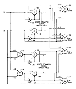
More specifically, in Figure 4, the L, and Rt inputs are applied first to a
passive
matrix that includes combiners 2 and 4 as in the Figure 1 passive matrix
configuration.
The L, input, which is also the passive matrix "left" output, is applied to
the "left" VCA
32 and to one input of a linear combiner 34 with a scaling of + 1. The left
VCA 32
output is applied to a combiner 34 with a scaling of -1 (thus forming a
subtractor). The
Rt input, which is also the passive matrix "right" output, is applied to the
"right" VCA
44 and to one input of a linear combiner 46 with a scaling of + 1. The right
VCA 44
output is applied to the combiner 46 with a scaling of -1 (thus forming a
subtractor).
The outputs of combiners 34 and 46 are the signals L,*(1-g) and Rt*(1-g,),
respectively,
and it is desired to keep the magnitude of those signals equal or to urge them
toward
equality. To achieve that result, those signals preferably are applied to a
feedback
circuit such as shown in Figure 3 and described in connection therewith. The
feedback
circuit then controls the gain of VCAs 32 and 44.
In addition, still referring to Figure 4, the "center" output of the passive
matrix
from combiner 2 is applied to the "center" VCA 36 and to one input of a linear
combiner 38 with a scaling of + 1. The center VCA 36 output is applied to the
combiner 38 with a scaling of -1 (thus forming a subtractor). The "surround"
output of
the passive matrix from combiner 4 is applied to the "surround" VCA 40 and to
one
input of a linear combiner 42 with a scaling of + 1. The surround VCA 40
output is
applied to the combiner 42 with a scaling of -1 (thus forming a subtractor).
The outputs
) and 'h*(I.,-R,)*(1-ge),
of combiners 38 and 42 are the signals 'h*(L,+R)*(1-gc
respectively, and it is desired to keep the magnitude of those signals equal
or to urge
them toward equality. To achieve that result, those signals preferably are
applied to a
feedback circuit such as shown in Figure 3 and described in connection
therewith. The
feedback circuit then controls the gain of VCAs 38 and 42.
The output signals L.,, C0LL,, S0,, , and R,,õ, are produced by combiners 48,
50, 52
and 54. Each combiner receives the output of two VCAs (the VCA outputs
constituting
CA 02392601 2002-05-23
WO 01/41504 PCT/US00/32383
- 18-
a component of the intermediate signals whose magnitudes are sought to be kept
equal)
to provide cancellation signal components and either or both input signals so
as to
provide passive matrix signal components. More specifically, the input signal
L, is
applied with a scaling of + 1 to the L., combiner 48, with a scaling of +'/2
to the Cam,,
combiner 50, and with a scaling of +'/2 to the S,,., combiner 52. The input
signal R, is
applied with a scaling of + 1 to the R.,. combiner 54, with a scaling of +'/2
to C0
combiner 50, and with a scaling of -1/2 to Soõ, combiner 52. The left VCA 32
output is
applied with a scaling of -1/2 to C(,,1 combiner 50 and also with a scaling of
-1/2 to S
combiner 52. The right VCA 44 output is applied with a scaling of -1/2 to Ce,,
combiner
50 and with a scaling of +'/2 to Soõ, combiner 52. The center VCA 36 output is
applied
with a scaling of -1 to La., combiner 48 and with a scaling of -1 to Ra,,
combiner 54.
The surround VCA 40 output is applied with a scaling of -1 to L.., VCA 48 and
with a
scaling of + 1 to Rte,, VCA 54.
It will be noted that in various ones of the figures, for example in Figures 2
and
4, it may initially appear that cancellation signals do not oppose the passive
matrix
signals (for example, some of the cancellation signals are applied to
combiners with the
same polarity as the passive matrix signal is applied). However, in operation,
when a
cancellation signal becomes significant it will have a polarity that does
oppose the
passive matrix signal.
Another arrangement equivalent to the combination of Figures 2 and 3 and to
Figure 4 is shown functionally and schematically in Figure 5 . In the Figure 5
configuration, the signals that are to be maintained equal are the signals
applied to the
output deriving combiners and to the feedback circuits for control of the
VCAs. These
signals include passive matrix output signal components. In contrast, in the
arrangement of Figure 4 the signals applied to the output combiners from the
feedback
circuits are the VCA output signals and exclude the passive matrix components.
Thus,
in Figure 4 (and in the combination of Figures 2 and 3), passive matrix
components
must be explicitly combined with the outputs of the feedback circuits, whereas
in Figure
CA 02392601 2002-05-23
WO 01/41504 PCT/US00/32383
-19-
the outputs of the feedback circuits include the passive matrix components and
are
sufficient in themselves. It will also be noted that in the Figure 5
arrangement the
intermediate signal outputs rather than the VCA outputs (each of which
constitutes only
a component of the intermediate signal) are applied to the output combiners.
5 Nevertheless, the Figure 4 and Figure 5 (along with the combination of
Figures 2 and 3)
configurations are equivalent, and, if the summing coefficients are accurate,
the outputs
from Figure 5 are the same as those from Figure 4 (and the combination of
Figures 2
and 3).
In Figure 5, the four intermediate signals, [1/2*(LL+R)*(1-g,,)], [1h*(LL-
R)*(1-
g8), [1/2*LL*(1-g)], and ['h*R1*(1-g,.)], in the equations 9, 10, 11 and 12
are obtained by
processing the passive matrix outputs and are then added or subtracted to
derive the
desired outputs. The signals also are fed to the rectifiers and comparators of
two
feedback circuits, as described above in connection with Figure 3, the
feedback circuits
desirably acting to hold the magnitudes of the pairs of signals equal. The
feedback
circuits of Figure 3, as applied to the Figure 5 configuration, have their
outputs to the
output combiners taken from the outputs of the combiners 22 and 26 rather than
from
the VCAs 6 and 12.
Still referring to Figure 5, the connections among combiners 2 and 4, VCAs 32,
36, 40, and 44, and combiners 34, 38, 42 and 46 are the same as in the
arrangement of
Figure 4. Also, in both the Figure 4 and Figure 5 arrangements, the outputs of
the
combiners 34, 38, 42 and 46 preferably are applied to two feedback control
circuits (the
outputs of combiners 34 and 46 to a first such circuit in order to generate
control signals
for VCAs 32 and 44 and the outputs of combiners 38 and 42 to a second such
circuit in
order to generate control signals for VCAs 36 and 40). In Figure 5 the output
of
combiner 34, the LL*(1-g,) signal, is applied with a scaling of + 1 to the CA,
combiner
58 and with a scaling of + 1 to the Soo, combiner 60. The output of combiner
46, the
RL*(1-g) signal is applied with a scaling of + 1 to the C, combiner 58 and
with a
scaling of -1 to the SoõL combiner 60. The output of combiner 38, the
1h*(LL+R)*(1-g,,)
CA 02392601 2002-05-23
WO 01/41504 PCT/US00/32383
-20-
signal, is applied to the LO., combiner 56 with a scaling of + 1 and to the
Rte,, combiner
62 with a scaling of + 1. The output of the combiner 42, the 'h*(L, R)*(1-g)
signal, is
applied to the La", combiner 56 with a +I scaling and to the R.., combiner 62
with a -1
scaling.
Unlike prior art adaptive matrix decoders, whose control signals are generated
from the inputs, the invention preferably employs a closed-loop control in
which the
magnitudes of the signals providing the outputs are measured and fed back to
provide
the adaptation. In particular, unlike prior art open-loop systems, the desired
cancellation of unwanted signals for non-cardinal directions does not depend
on an
accurate matching of characteristics of the signal and control paths, and the
closed-loop
configurations greatly reduce the need for precision in the circuitry.
Ideally, aside from practical circuit shortcomings, "keep magnitudes equal"
configurations of the invention are "perfect" in the sense that any source fed
into the L,
and R, inputs with known relative amplitudes and polarity will yield signals
from the
desired outputs and negligible signals from the others. "Known relative
amplitudes and
polarity" means that the L, and R, inputs represent either a cardinal
direction or a
position between adjacent cardinal directions.
Considering the equations 9, 10, 11 and 12 again, it will be seen that the
overall
gain of each variable gain circuit incorporating a VCA is a subtractive
arrangement in
the form (1-g). Each VCA gain can vary from a small value up to but not
exceeding
unity. Correspondingly, the variable-gain-circuit gain (1-g) can vary from
very nearly
unity down to zero. Thus, Figure 5 can be redrawn as Figure 6, where every VCA
and
associated subtractor has been replaced by a VCA alone, whose gain varies in
the
opposite direction to that of the VCAs in Figure 5. Thus every variable-gain-
circuit
gain (1-g) (implemented, for example by a VCA having a gain "g" whose output
is
subtracted from a passive matrix output as in Figures 2/3, 4 and 5) is
replaced by a
corresponding variable-gain-circuit gain "h" (implemented, for example by a
stand-
alone VCA having a gain "h" acting on a passive matrix output). If the
characteristics
CA 02392601 2002-05-23
WO 01/41504 PCT/US00/32383
-21-
of gain "(1-g)" is the same as gain "h" and if the feedback circuits act to
maintain
equality between the magnitude of the requisite pairs of signals, the Figure 6
configuration is equivalent to the Figure 5 configuration and will deliver the
same
outputs. Indeed, all of the disclosed configurations, the configurations of
Figures 2/3,
4, 5, and 6, are equivalent to each other.
Although the Figure 6 configuration is equivalent and functions exactly the
same
as all the prior configurations, note that the passive matrix does not appear
explicitly but
is implicit. In the quiescent or unsteered condition of the prior
configurations, the VCA
gains g fall to small values. In the Figure 6 configuration, the corresponding
unsteered
condition occurs when all the VCA gains h rise to their maximum, unity or
close to it.
Referring to Figure 6 more specifically, the "left" output of the passive
matrix,
which is also the same as the input signal Lõ is applied to a "left" VCA 64
having a
gain h, to produce the intermediate signal L,*h,. The "right" output of the
passive
matrix, which is also the same as the input signal P, is applied to a "right"
VCA 70
having a gain h, to produce the intermediate signal R,*h,. The "center" output
of the
passive matrix from combiner 2 is applied to a "center" VCA 66 having a gain
he to
produce an intermediate signal 'h *(L,+R)*h,. The "surround" output of the
passive
matrix from combiner 4 is applied to a "surround" VCA 68 having a gain h8 to
produce
an intermediate signal l/2*(L1 R)*h8. As explained above, the VCA gains h
operate
inversely to the VCA gains g, so that the h gain characteristics are the same
as the (1-g)
gain characteristics.
Generation of control voltages
An analysis of the control signals developed in connection with the
embodiments
described thus far is useful in better understanding the present invention and
in
explaining how the teachings of the present invention may be applied to
deriving five or
more audio signal streams, each associated with a direction, from a pair of
audio input
signal streams.
In the following analysis, the results will be illustrated by considering an
audio
CA 02392601 2002-05-23
WO 01/41504 PCT/US00/32383
-22-
source that is panned clockwise around the listener in a circle, starting at
the rear and
going via the left, center front, right and back to the rear. The variable a
is a measure
of the angle (in degrees) of the image with respect to a listener, 0 degrees
being at the
rear and 180 degrees at the center front. The input magnitudes L, and R, are
related to
a by the following expressions:
Lt = cos (a - 90)
360 (Eqn. 17A)
C
Rt = sin C )r (a - 90) (Eqn. 17B)
360 J 15 There is a one-to-one mapping between the parameter a and the ratio
of the
magnitudes and the polarities of the input signals; use of a leads to more
convenient
analysis. When a is 90 degrees, L, is finite and R, is zero, i.e., left only.
When a is
180 degrees, L, and R, are equal with the same polarity (center front). When a
is 0, L,
and R, are equal but with opposite polarities (center rear). As is explained
further
below, particular values of interest occur when L, and R, differ by 5 dB and
have
opposite polarity; this yields a values of 31 degrees either side of zero. In
practice, the
left and right front loudspeakers are generally placed further forward than +/-
90
degrees relative to the center (for example, +/- 30 to 45 degrees), so a does
not
actually represent the angle with respect to the listener but is an arbitrary
parameter to
illustrate panning. The figures to be described are arranged so that the
middle of the
horizontal axis (a= 180 degrees) represents center front and the left and
right extremes
(a=0 and 360) represent the rear.
As discussed above in connection with the description of Figure 3, a
convenient
CA 02392601 2002-05-23
WO 01/41504 PCT/US00/32383
-23-
and practical relationship between the gains of a pair of VCAs in a feedback-
derived
control system holds their product constant. With exponentially controlled
VCAs fed so
that as the gain of one rises the gain of the other falls, this happens
automatically when
the same control signal feeds both of the pair, as in the embodiment of Figure
3.
Denoting the input signals by L, and R,, setting the product of the VCA gains
g,
and g,. equal to 1/a2, and assuming sufficiently great loop-gain that the
resultant urging
towards equality is complete, the feedback-derived control system of Figure 3
adjusts
the VCA gains so that the following equation is satisfied:
I Lt l = (1- gl) = I Rt l . (1- gr) (Eqn. 18)
In addition,
gl . gr = 2 (Eqn. 19)
a
Clearly, in the first of these equations, the absolute magnitudes of L, and R,
are
irrelevant. The result depends only on their ratio L,/R,; call this X.
Substituting gr
from the second equation into the first, one obtains a quadratic equation in
g, that has
the solution (the other root of the quadratic does not represent a real
system):
I_ 1 (X a2 a2 + a2=(X2=a2-2=X=a2+a2+4=X)] (Egn.20)
g 2 X=a2
Plotting g, and g, against the panning angle a, one obtains Figure 7. As might
be expected, g, rises from a very low value at the rear to a maximum of unity
when the
input represents left only (a=90) and then falls back to a low value for the
center front
(a=180). In the right half, g, remains very small. Similarly and
symmetrically, g, is
small except in the middle of the right half of the pan, rising to unity when
a is 270
degrees (right only).
CA 02392601 2002-05-23
WO 01/41504 PCT/US00/32383
-24-
The above results are for the L,/R, feedback-derived control system. The
sum/difference feedback-derived control system acts in exactly the same
manner,
yielding plots of sum gain g. and difference gain g, as shown in Figure 8.
Again, as
expected, the sum gain rises to unity at the center front, falling to a low
value
elsewhere, while the difference gain rises to unity at the rear.
If the feedback-derived control system VCA gains depend on the exponent of the
control voltage, as in the preferred embodiment, then the control voltage
depends on the
logarithm of the gain. Thus, from the equations above, one can derive
expressions for
the L4R, and sum/difference control voltages, namely, the output of the
feedback-
derived control system's comparator, comparator 30 of Figure 3. Figure 9 shows
the
left/right and the sum/difference control voltages, the latter inverted (i.e.,
effectively
difference/sum), in an embodiment where the maximum and minimum values of
control
signals are + /-15 volts. Obviously, other scalings are possible.
The curves in Figure 9 cross at two points, one where the signals represent an
image somewhere to the left back of the listener and the other somewhere in
the front
half. Due to the symmetries inherent in the curves, these crossing points are
exactly
half-way between the a values corresponding to adjacent cardinal directions.
In Figure
9, they occur at 45 and 225 degrees.
Prior art (e.g., U.S. patent 5,644,640 of the present inventor James W.
Fosgate)
shows that it is possible to derive from two main control signals a further
control signal
that is the greater (more positive) or lesser (less positive) of the two,
although that prior
art derives the main control signals in a different manner and makes different
use of the
resultant control signals. Figure 10 illustrates a signal equal to the lesser
of the curves
in Figure 9. This derived control rises to a maximum when a is 45 degrees,
that is, the
value where the original two curves crossed.
It may not be desirable for the maximum of the derived control signal to rise
to
its maximum precisely at a=45. In practical embodiments, it is preferable for
the
derived cardinal direction representing left back to be nearer to the back,
that is, to have
CA 02392601 2002-05-23
WO 01/41504 PCT/US00/32383
-25-
a value that is less than 45 degrees. The precise position of the maximum can
be
moved by offsetting (adding or subtracting a constant to) or scaling one or
both of the
left/right and sum/difference control signals so that their curves cross at
preferred
values of a, before taking the more-positive or more-negative function. For
instance,
Figure 11 shows the same operation as Figure 10 except that the sum/difference
voltage
has been scaled by 0.8, with the result that the maximum now occurs at a=31
degrees.
In exactly the same manner, comparing the inverted left/right control with the
inverted sum/difference and employing similar offsetting or scaling, a second
new
control signal can be derived whose maximum occurs in a predetermined position
corresponding to the right back of the listener, at a desired and
predetermined a (for
instance, 360-31 or 329 degrees, 31 degrees the other side of zero,
symmetrical with
the left back). It is a left/right reversal of Figure 11.
Figure 12 shows the effect of applying these derived control signals to VCAs
in
such a manner that the most positive value gives a gain of unity. Just as the
left and
right VCAs give gains that rise to unity at the left and right cardinal
directions, so these
derived left back and right back VCA gains rise to unity when a signal is
placed at
predetermined places (in this example, a=31 degrees either side of zero), but
remain
very small for all other positions.
Similar results can be obtained with linearly controlled VCAs. The curves for
the main control voltages versus panning parameter a will be different, but
will cross at
points that can be chosen by suitable scaling or offsetting, so further
control voltages for
specific image positions other than the initial four cardinal directions can
be derived by
a lesser-than operation. Clearly, it is also possible to invert the control
signals and
derive new ones by taking the greater (more positive) rather than the lesser
(more
negative).
The modification of the main control signals to move their crossing point
before
taking the greater or lesser may alternatively consist of a non-linear
operation instead of
or in addition to an offset or a scaling. It will be apparent that the
modification allows
CA 02392601 2002-05-23
WO 01/41504 PCT/US00/32383
-26-
the generation of further control voltages whose maxima lie at almost any
desired ratio
of the magnitudes and relative polarities of L, and R, (the input signals).
An adaptive matrix with more than four outputs
Figures 2 and 4 showed that a passive matrix may have adaptive cancellation
terms added to cancel unwanted crosstalk. In those cases, there were four
possible
cancellation terms derived via four VCAs, and each VCA reached a maximum gain,
generally unity, for a source at one of the four cardinal directions and
corresponding to
a dominant output from one of the four outputs (left, center, right and rear).
The
system was perfect in the sense that a signal panned between two adjacent
cardinal
directions yielded little or nothing from outputs other than those
corresponding to the
two adjacent cardinal outputs.
This principle may be extended to active systems with more than four outputs.
In such cases, the system is not "perfect," but unwanted signals may still be
sufficiently
cancelled that the result is audibly unimpaired by crosstalk. See, for
example, the six
output matrix of Figure 13. Figure 13, a functional and schematic diagram of a
portion
of an active matrix according to the present invention, is a useful aid in
explaining the
manner in which more than four outputs are obtained. Figure 14 shows the
derivation
of six cancellation signals usable in Figure 13.
Referring first to Figure 13, there are six outputs: left front (L.), center
front
(Co,,), right front (Ra,,), center back (or surround) (S.), right back (RB.,)
and left back
(LB.,,). For the three front and surround outputs, the initial passive matrix
is the same
as that of the four-output system described above (a direct L, input, the
combination of
L1 plus R, scaled by one-half and applied to a linear combiner 80 to yield
center front,
the combination of L, minus R, scaled by one-half and applied to a linear
combiner 82 to
yield center back, and a direct R, input). There are two additional back
outputs, left
back and rear back, resulting from applying L1 with a scaling of 1 and R, with
a scaling
of -b to a linear combiner 84 and applying L1 with a scaling of -b and Rt with
a scaling
of 1 to a linear combiner 86, corresponding to different combinations of the
inputs in
CA 02392601 2002-05-23
WO 01/41504 PCT/US00/32383
-27-
accordance with the equations LB.õ, = L, - b*R, and RB0õ, = Rt - b*L1. Here, b
is a
positive coefficient typically less than 1, for example, 0.25. Note the
symmetry that is
not essential to the invention but would be expected in any practical system.
In Figure 13, in addition to the passive matrix terms, the output linear
combiners
(88, 90, 92, 94, 96 and 98) receive multiple active cancellation terms (on
lines 100,
102, 104, 106, 108, 110, 112, 114, 116, 118, 120 and 122) as required to
cancel the
passive matrix outputs. These terms consist of the inputs and/or combinations
of the
inputs multiplied by the gains of VCAs (not shown) or combinations of the
inputs and
the inputs multiplied by the gains of VCAs. As described above, the VCAs are
controlled so that their gains rise to unity for a cardinal input condition
and are
substantially smaller for other conditions.
The configuration of Figure 13 has six cardinal directions, provided by inputs
L,
and Rt in defined relative magnitudes and polarities, each of which should
result in
signals from the appropriate output only, with substantial cancellation of
signals in the
other five outputs. For an input condition representing a signal panned
between two
adjacent cardinal directions, the outputs corresponding to those cardinal
directions
should deliver signals but the remaining outputs should deliver little or
nothing. Thus,
one expects that for each output, in addition to the passive matrix there will
be several
cancellation terms (in practice, more than the two shown in Figure 13), each
corresponding to the undesired output for an input corresponding to each of
the other
cardinal directions. In practice, the arrangement of Figure 13 may be modified
to
eliminate the center back S., output (thus eliminating combiners 82 and 94) so
that
center back is merely a pan half-way between left back and right back rather
than a
sixth cardinal direction.
For either the six-output system of Figure 13 or its five-output alternative
there
are six possible cancellation signals: the four derived via the two pairs of
VCAs that
are parts of the left/right and sum/difference feedback-derived control
systems and two
more derived via left back and right back VCAs controlled as described above
(see also
CA 02392601 2002-05-23
WO 01/41504 PCT/US00/32383
-28-
the embodiment of Figure 14, described below). The gains of the six VCAs are
in
accordance with Figure 7 (g, left and g, right), Figure 8 (g,, sum and ge
difference) and
Figure 12 (g,, left back and g,, right back). The cancellation signals are
summed with
the passive matrix terms using coefficients calculated or otherwise chosen to
minimize
unwanted crosstalk, as described below.
One arrives at the required cancellation mixing coefficients for each cardinal
output by considering the input signals and VCA gains for every other cardinal
direction, remembering that those VCA gains rise to unity only for signals at
the
corresponding cardinal direction, and fall away from unity fairly rapidly as
the image
moves away.
Thus, for instance, in the case of the left output, one needs to consider the
signal
conditions for center front, right only, right back, center back (not a real
cardinal
direction in the five-output case) and left back.
Consider in detail the left output, Lo,,, for the five-output modification of
Figure
13. It contains the term from the passive matrix, L,. To cancel the output
when the
input is in the center, when L, = R, and g. = 1, one needs the term -
'h*g,,*(L,+R,),
exactly as in the four-output system of Figures 2 or 4. To cancel when the
input is at
center back or anywhere between center back and right front (therefore
including right
back), one needs -1/2 *gB*(L, R), again exactly as in the four-output system
of Figures 2
or 4. To cancel when the input represents left back, one needs a signal from
the left
back VCA whose gain gm varies as in Figure 12. This can clearly deliver a
significant
cancellation signal only when the input lies in the region of left back. Since
the left
back can be considered as somewhere between left front, represented by L,
only, and
center back, represented by '/2*(Li-R), it is to be expected that the left
back VCA
should operate on a combination of those signals.
Various fixed combinations can be used, but by using a sum of the signals that
have already passed through the left and difference VCAs, i.e., g,*L, and '/2
*ge*(Lj-R),
the combination varies in accordance with the position of signals panned in
the region
CA 02392601 2002-05-23
WO 01/41504 PCT/US00/32383
-29-
of, but not exactly at, left back, providing better cancellation for those
pans as well as
the cardinal left back itself. Note that at this left back position, which can
be
considered as intermediate between left and rear, both g, and g, have finite
values less
than unity. Hence the expected equation for La,,, will be:
Last = [I.,]-'/2*g~*( +R,)-'/a*ge*( - -x*g-b*((g~* -I-ge*'h*(L ..R~) (Eqn. 21)
The coefficient x can be derived empirically or from a consideration of the
precise VCA gains when a source is in the region of the left back cardinal
direction.
The term [L] is the passive matrix term. The terms 'h*g,*(L,+R), -'h*ge*(L,-R
), and
'/z*x*g,b*((g,*L,+ge*'h*(L1 R,)) represent cancellation terms (see Figure 14)
that may be
combined with L, in linear combiner 88 (Figure 13) in order to derive the
output audio
signal Lo,. As explained above, there may be more than two crosstalk
cancellation term
inputs than the two (100 and 102) shown in Figure 13.
The equation for R,,., is derived similarly, or by symmetry:
R. = [R,]-'/z*g.*(L +R.)+'/z*ga*(Li-R)-'/2*x*gb*((g,.*Rt-ga*(L, R)) (Eqn. 22)
The term [R,] is the passive matrix term. The terms -'/z*g,*(L,+R), '/z*g,*(L,-
R), and -'/z*x*gb*((g,*R,-gg*(L, R)) represent cancellation terms (see Figure
14) that
may be combined with R, in linear combiner 98 (Figure 13) in order to derive
the output
audio signal R.,,,. As explained above, there may be more than two crosstalk
cancellation term inputs than the two (120 and 122) shown in Figure 13.
The center front output, Cam,,, contains the passive matrix term '/z*(L,+R,),
plus
the left and right cancellation terms as for the four-output system, -'h*g,*L,
and
-'/z *gr*R,:
C0, =['/2(L,+R,)]-'/z*g,*L,*-'h*g~*R,* (Eqn. 23)
CA 02392601 2002-05-23
WO 01/41504 PCT/US00/32383
-30-
There is no need for explicit cancellation terms for the left back, center
back or right
back since they are effectively pans between left and right front via the back
(surround,
in the four-output) and already cancelled. The term ['h(L,+R)] is the passive
matrix
term. The terms -1/2*g,*L, and -'h*g,*Rt represent cancellation terms (see
Figure 14)
that may be applied to inputs 100 and 102 and combined with a scaled version
of Lt and
R, in linear combiner 90 (Figure 13) in order to derive the output audio
signal C.
For the left back output, the starting passive matrix, as stated above, is L, -
b*R,.
For a left only input, when g, = 1, clearly the required cancellation term is
therefore
-g,*L,. For a right only input, when g, = 1, the cancellation term is
+b*g,*R,. For a
center front input, where L, = R, and g. = 1, the unwanted output from the
passive
terms, Lt-b*Rõ can be cancelled by (1-b)*g,,*1/2*(L,+R). The right back
cancellation
term is -gt,*(g,*R,-'h*g.*(L,-R)), the same as the term used for Rte,,, with
an optimized
coefficient y, which may again be arrived at empirically or calculated from
the VCA
gains in the left or right back conditions. Thus,
LB.. = [Lt-b*Rj-g,*L,+b*gr*R,-(1-b)*g.*' *(Lt+Rt)-y*ge.*(g,*R,-g.*'fi*(L,-R))
(Eqn. 24)
Similarly,
RBa,,, = [R-b*W-g,*R,+b*gi*L,{1-b)*g.*'h*(L+R)-Y*gib*(gi*1,+g.*'/2*(L R.))
(Eqn. 25)
With respect to equation 24, the term [Lt-b*Rt] is the passive matrix term and
the terms -g,*Lõ +b*g,*Rt, -'h*(1-b)*g,,*(Lt+R) and -y*grb*((gr*Rt-gs*'h*(Lt-
Rt))
represent cancellation terms (see Figure 14) that may be combined with Li bR,
in linear
combiner 92 (Figure 13) in order to derive the output audio signal LB.,,,. As
explained
above, there may be more than two crosstalk cancellation term inputs than the
two (108
CA 02392601 2002-05-23
WO 01/41504 PCT/US00/32383
-31 -
and 110) shown in Figure 13.
With respect to equation 25, the [R,-b*Lj is the passive matrix term and the
components -g1*Rt, b*L,*gl, -V2*(1-b)*g,;*(I.,+R), and -
y*g1b*((g1*L,+g,*1/2*(Lj-RJ)
represent cancellation terms (see Figure 14) that may be combined with R,-b*L,
in linear
combiner 96 (Figure 13) in order to derive the output audio signal RB0, As
explained
above, there may be more than two crosstalk cancellation term inputs than the
two (116
and 118) shown in Figure 13.
In practice, all the coefficients may need adjustments to compensate for the
finite
loop-gains and other imperfections of the feedback-derived control systems,
which do
not deliver precisely equal signal levels, and other combinations of the six
cancellation
signals may be employed.
These principles can, of course, be extended to embodiments having more than
five or six outputs. Yet additional control signals can be derived by further
application
of the scaling, offsetting or non-linear processing of the two main control
signals from
the left/right and sum/difference feedback portions of the feedback-derived
control
systems, permitting the generation of additional cancellation signals via VCAs
whose
gains rise to maxima at other desired predetermined values of a. The synthesis
process
of considering each output in the presence of signals at each of the other
cardinal
directions in turn will yield appropriate terms and coefficients for
generating additional
outputs.
Referring now to Figure 14, input signals Lt and Rt are applied to a passive
matrix 130 that produces a left matrix signal output from the L, input, a
right matrix
signal output from the R, input, a center output from a linear combiner 132
whose input
is LL and R, each with a scale factor of +'h, and a surround output from a
linear
combiner 134 whose input is L, and Rt with scale factors of +'/2 and -1/2,
respectively.
The cardinal directions of the passive matrix are designated "left," "center,"
"right,"
and "surround." Adjacent cardinal directions lie on mutually orthogonal axes,
such
that, for these direction labels, left is adjacent to center and surround;
surround is
CA 02392601 2002-05-23
WO 01/41504 PCT/US00/32383
-32-
adjacent to left and right, etc.
The left and right passive matrix signals are applied to a first pair of
variable
gain circuits 136 and 138 and associated feedback-derived control system 140.
The
center and surround passive matrix signals are applied to a second pair of
variable gain
circuits 142 and 144 and associated feedback-derived control system 146.
The "left" variable gain circuit 136 includes a voltage controlled amplifier
(VCA) 148 having a gain g, and a linear combiner 150. The VCA output is
subtracted
from the left passive matrix signal in combiner 150 so that the overall gain
of the
variable gain circuit is (1-g) and the output of the variable gain circuit at
the combiner
output, constituting an intermediate signal, is (1-g)*L,. The VCA 148 output
signal,
constituting a cancellation signal, is g,*I,,
The "right" variable gain circuit 138 includes a voltage controlled amplifier
(VCA) 152 having a gain g,, and a linear combiner 154. The VCA output is
subtracted
from the right passive matrix signal in combiner 154 so that the overall gain
of the
variable gain circuit is (1-g) and the output of the variable gain circuit at
the combiner
output, constituting an intermediate signal, is (1-g,.)*R,. The VCA 152 output
signal
g,*R, constitutes a cancellation signal. The (1-g)*R, and (1-g)*L,
intermediate signals
constitute a first pair of intermediate signals. It is desired that the
relative magnitudes
of this first pair of intermediate signals be urged toward equality. This is
accomplished
by the associated feedback-derived control system 140, described below.
The "center" variable gain circuit 142 includes a voltage controlled amplifier
(VCA) 156 having a gain gc and a linear combiner 158. The VCA output is
subtracted
from the center passive matrix signal in combiner 158 so that the overall gain
of the
variable gain circuit is (1-ge) and the output of the variable gain circuit at
the combiner
output, constituting an intermediate signal, is'/z*(1-gc)*(L,+R,). The VCA 156
output
signal '/z*g,,*(L,+R) constitutes a cancellation signal.
The "surround" variable gain circuit 144 includes a voltage controlled
amplifier
(VCA) 160 having a gain g,. and a linear combiner 162. The VCA output is
subtracted
CA 02392601 2002-05-23
WO 01/41504 PCT/US00/32383
-33-
from the surround passive matrix signal in combiner 162 so that the overall
gain of the
variable gain circuit is (1-g8) and the output of the variable gain circuit at
the combiner
output, constituting an intermediate signal, is'/2*(1-gJ*(L,-RJ. The VCA 160
output
signal'/2*ge)*(L,-R,) constitutes a cancellation signal. The'/2*(1-
g,,)*(L,+R,) and'/2*(1-
g,)*(L,-R) intermediate signals constitute a second pair of intermediate
signals. It is
also desired that the relative magnitudes of this second pair of intermediate
signals be
urged toward equality. This is accomplished by the associated feedback-derived
control
system 146, described below.
The feedback-derived control system 140 associated with the first pair of
intermediate signals includes filters 164 and 166 receiving the outputs of
combiners 150
and 154, respectively. The respective filter outputs are applied to log
rectifiers 168 and
170 that rectify and produce the logarithm of their inputs. The rectified and
logged
outputs are applied with opposite polarities to a linear combiner 172 whose
output,
constituting a subtraction of its inputs, is applied to a non-inverting
amplifier 174
(devices 172 and 174 correspond to the magnitude comparator 30 of Figure 3).
Subtracting the logged signals provides a comparison function. As mentioned
above,
this is a practical way to implement a comparison function in the analog
domain. In this
case, VCAs 148 and 152 are of the type that inherently take the antilog of
their control
inputs, thus taking the antilog of the control output of the logarithmically-
based
comparator. The output of amplifier 174 constitutes a control signal for VCAs
148 and
152. As mentioned above, if implemented digitally, it may be more convenient
to
divide the two magnitudes and use the resultants as direct multipliers for the
VCA
functions. As noted above, the filters 164 and 166 may be derived empirically,
providing a response that attenuates low frequencies and very high frequencies
and
provides a gently rising response over the middle of the audible range. These
filters do
not alter the frequency response of the output signals, they merely alter the
control
signals and VCA gains in the feedback-derived control systems.
The feedback-derived control system 146 associated with the second pair of
CA 02392601 2002-05-23
WO 01/41504 PCT/US00/32383
-34-
intermediate signals includes filters 176 and 178 receiving the outputs of
VCAs 158 and
162, respectively. The respective filter outputs are applied to log rectifiers
180 and 182
that rectify and produce the logarithm of their inputs. The rectified and
logged outputs
are applied with opposite polarities to a linear combiner 184 whose output,
constituting
a subtraction of its inputs, is applied to a non-inverting amplifier 186
(devices 184 and
186 correspond to the magnitude comparator 30 of Figure 3). The feedback-
derived
control system 146 operates in the same manner as control system 140. The
output of
amplifier 186 constitutes a control signal for VCAs 158 and 162.
Additional control signals are derived from the control signals of feedback-
derived control systems 140 and 146. The control signal of control system 140
is
applied to first and second scaling, offset, inversion, etc. functions 188 and
190. The
control signal of control system 146 is applied to first and second scaling,
offset,
inversion, etc. functions 192 and 194. Functions 188, 190, 192 and 194 may
include
one or more of the polarity inverting, amplitude offsetting, amplitude scaling
and/or
non-linearly processing described above. Also in accordance with descriptions
above,
the lesser or the greater of the outputs of functions 188 and 192 and of
functions 190
and 194 are taken in by lesser or greater functions 196 and 198, respectively,
in order
to produce additional control signals that are applied to a left back VCA 200
and a right
back VCA 202, respectively. In this case, the additional control signals are
derived in
the manner described above in order to provide control signals suitable for
generating a
left back cancellation signal and a right back cancellation signal. The input
to left back
VCA 200 is obtained by additively combining the left and surround cancellation
signals
in a linear combiner 204. The input to right back VCA 202 is obtained by
subtractively
combining the right and surround cancellation signals in a linear combiner
204.
Alternatively and less preferably, the inputs to the VCAs 200 and 202 may be
derived
from the left and surround passive matrix outputs and from the right and
surround
passive matrix output, respectively. The output of left back VCA 200 is the
left back
cancellation signal g,,*1h*((g,*L(+ge(L1 Rt)). The output of right back VCA
202 is the
CA 02392601 2002-05-23
WO 01/41504 PCT/US00/32383
-35-
right back cancellation signal g,,,*'/2*((g,*R,+g,(L,-Rt)).
Figure 15 is a schematic circuit diagram showing a practical circuit embodying
aspects of the present invention. Resistor values shown are in ohms. Where not
indicated, capacitor values are in microfarads.
In Figure 15, "TL074" is a Texas Instruments' quad low-noise JFET-input (high
input impedance) general purpose operational amplifier intended for high-
fidelity and
audio preamplifier applications. Details of the device are widely available in
published
literature. A data sheet may be found on the Internet at
< <http://www.ti.com/sc/docs/products/analog/t1074.html> >.
"SSM-2120" in Figure 15 is a monolithic integrated circuit intended for audio
applications. It includes two VCAs and two level detectors, allowing
logarithmic
control of the gain or attenuation of signals presented to the level detectors
depending
on their magnitudes. Details of the device are widely available in published
literature.
A data sheet may be found on the Internet at <
<http://www.analog.com/pdf/1788_c.pdf> >.
The following table relates terms used in this document to the labels at the
VCA
outputs and to the labels on the vertical bus of Figure 15.
Terms used Label at Label on
in the above output of VCA vertical bus
description of Figure 15 Figure 15
g,*L, Left VCA LVCA
gr*R, Right VCA RVCA
'/2*gc,*(L,+R) Front VCA FVCA
'/2*ga*(4-R) Back VCA BVCA
g,b*((g,*L,+ge*'/2*(L,-R)) Left Back VCA LBVCA
g6*((gr*R,-ge*'/2*(L,-R)) Right Back VCA RBVCA
CA 02392601 2002-05-23
WO 01/41504 PCT/US00/32383
-36-
In Figure 15, the labels on the wires going to the output matrix resistors are
intended to convey the functions of the signals, not their sources. Thus, for
example,
the top few wires leading to the left front output are as follows:
Label in Figure 15 Meaning
LT The contribution from the L, input
CF Cancel The signal to cancel the unwanted
output for a center front source
LB Cancel The signal to cancel the unwanted
output for a left back source
BK Cancel The signal to cancel the unwanted
output for a back source
RB Cancel The signal to cancel the unwanted
source for a right back source
LF GR Left front gain riding - to make a pan
across the front give a more constant
loudness
Note that in Figure 15, whatever the polarity of the VCA terms, the matrix
itself
has provision for inversion of any terms (U2C, etc.). In addition, "servo" in
Figure 15
refers to the feedback derived control system as described herein.
The present invention may be implemented using analog, hybrid analog/digital
and/or digital signal processing in which functions are performed in software
and/or
firmware. Analog terms such as VCA, rectifier etc. are intended to include
their digital
equivalents. For example, in a digital embodiment, a VCA is realized by
multiplication
or division.