Note: Descriptions are shown in the official language in which they were submitted.
CA 02392640 2002-07-05
A METHOD AND DEVICE FOR EFFICIENT IN-BAND DIM-AND-BURST
SIGNALING AND HALF-RATE MAX OPERATION IN VARIABLE BIT-
RATE WIDEBAND SPEECH CODING FOR CDMA WIRELESS
SYSTEMS
BACKGROUND OF THE INVENTION
1. Field of the Invention
The present invention relates to an improved technique for digitally
encoding a sound signal, in particular but not exclusively a speech signal, in
view
of transmitting and synthesizing this sound signal in a wireless CDMA system.
In
particular, the present invention relates to the design of variable bit-rate
CELP-
based coding capable of operating efficiently within the CDMA2000 system
requirements such as in-band dim-and-burst signalling and half rate max
operation. Further, the present invention relates to the design of variable
bit-rate
CELP-based coding capable of operating efficiently across other systems such
as
IP-based or W-CDMA systems in a tandem-free operation setup.
2. Brief Description of the Prior Art
Demand for e~cient digital narrowband and wideband speech coding
techniques with a good trade-off between the subjective quality and bit rate
is
increasing in various application areas such as teleconferencing, multimedia,
and
wireless communications. Until recently, telephone bandwidth constrained into
a
range of 200-3400 Hz has mainly been used in speech coding applications.
However, wideband speech applications provide increased intelligibility and
naturalness in communication compared to the conventional telephone bandwidth.
A bandwidth in the range 50-7000 Hz has been found sufficient for delivering a
good quality giving an impression of face-to-face communication. For general
audio signals, this bandwidth gives an acceptable subjective quality, but is
still
lower than the quality of FM radio or CD that operate on ranges of 20-16000 Hz
and 20-20000 Hz, respectively.
CA 02392640 2002-07-05
2
A speech encoder converts a speech signal into a digital bitstream which
is transmitted over a communication channel or stored in a storage medium. The
speech signal is digitized, that is, sampled and quantized with usually 16-
bits per
sample. The speech encoder has the role of representing these digital samples
with
a smaller number of bits while maintaining a good subjective speech quality.
The
speech decoder or synthesizer operates on the transmitted or stored bit stream
and
converts it back to a sound signal.
Code-Excited Linear Prediction (CELP) coding is one of the best prior
art techniques for achieving a good compromise between the subjective quality
and bit rate. This coding technique is a basis of several speech coding
standards
both in wireless and wireline applications. In CELP coding, the sampled speech
signal is processed in successive blocks of N samples usually called frames,
where
N is a predetermined number corresponding typically to 10-30 ms. A linear
prediction (LP) filter is computed and transmitted every frame. The
computation
of the LP filter typically needs a lookahead, a 5-15 ms speech segment from
the
subsequent frame. The N sample frame is divided into smaller blocks called
subframes. Usually the number of subframes is three or four resulting in 4-10
ms
subframes. In each subframe, an excitation signal is usually obtained from two
components, the past excitation and the innovative, fixed-codebook excitation.
The component formed from the past excitation is often referred to as the
adaptive
codebook or pitch excitation. The parameters characterizing the excitation
signal
are coded and transmitted to the decoder, where the reconstructed excitation
signal
is used as the input of the LP filter.
In wireless systems using code division multiple access (CDMA)
technology, the use of source-controlled variable bit rate (VBR) speech coding
significantly improves the system capacity. In source-controlled VBR coding,
the
codec operates at several bit rates, and a rate selection module is used to
determine
the bit rate used for encoding each speech frame based on the nature of the
speech
frame (e.g. voiced, unvoiced, transient, background noise). The goal is to
attain the
best speech quality at a given average bit rate, also referred to as average
data rate
(ADR). The codec can operate at different modes by tuning the rate selection
module to attain different ADRs at the different modes where the codec
performance is improved at increased ADRs. This enables the codec with a
mechanism of trade-off between speech quality and system capacity. In CDMA
CA 02392640 2002-07-05
3
systems (e.g. CDMA-one and CDMA2000), typically 4 bit rates are used and they
are referred to as full-rate (FR), half rate (HR), quarter-rate (QR), and
eighth-rate
(ER). In this system two rate sets are supported referred to as Rate Set I and
Rate
Set II. In Rate Set II, a variable-rate codec with rate selection mechanism
operates
at source-coding bit rates of 13.3 (FR), 6.2 (HR), 2.7 (QR), and 1.0 (ER)
kbit/s,
corresponding of gross bit rates of 14.4, 7.2, 3.6, and 1.8 kbit/s (with some
bits
added for error detection).
In CDMA systems, the system can impose the use of the half rate instead
of full-rate in some speech frames in order to send in-band signaling
information
(called dim-and-burst signaling). The use of half rate as a maximum bit rate
can be
also imposed by the system during bad channel conditions (such as near the
cell
boundaries) in order to improve the codec robustness. This is referred to as
half
rate max. Typically, in VBR coding, the half rate is used when the frame is
stationary voiced or stationary unvoiced. Two codec structures are used for
each
type of signal (in unvoiced case a CELP model without the pitch codebook is
used
and in voiced case signal modification is used to enhance the periodicity and
reduce the number of bits for the pitch indices). Full-rate is used for
onsets,
transient frames, and mixed voiced frames (a typical CELP model is usually
used).
When the rate-selection module chooses the frame to be encoded as a full-rate
frame and the system imposes the half rate frame the speech performance is
degraded since the half rate modes are not capable of efficiently encoding
onsets
and transient signals.
A wideband codec known as adaptive multi-rate wideband (AMR-WB)
speech codec was recently selected by the ITU-T (International
Telecommunications Union - Telecommunication Standardization Sector) for
several wideband speech telephony and services and by 3GPP (third generation
partnership project) for GSM and W-CDMA third generation wireless systems.
AMR-WB codec consists of nine bit rates in the range from 6.6 to 23.85 kbit/s.
Designing an AMR-WB-based source controlled VBR codec for CDMA2000
system has the advantage of enabling the interoperation between CDMA2000 and
other systems using the AMR-WB codec. The AMR-WB bit rate of 12.65 kbit/s is
the closest rate that can fit in the 13.3 kbit/s full-rate of Rate Set II.
This rate can
be used as the common rate between a CDMA2000 wideband VBR codec and
AMR-WB which will enable the interoperability without the need for transcoding
CA 02392640 2002-07-05
4
(which degrades the speech quality). A half rate at 6.2 kbit/s has to be added
to the
CDMA2000 VBR wideband solution to enable the efficient operation in the Rate
Set II framework. The codec then can operate in few CDMA2000-specific modes
but it will have a mode that enables interoperability with systems using the
AMR-
WB codec. However, in a cross-system tandem free operation call between
CDMA2000 and another system using AMR-WB, a case will arise where the
CDAM2000 system with force the use of the half rate as explained earlier (such
as
in dim-and-burst signaling). Since the AMR-WB codec doesn't recognize the 6.2
kbit/s half rate of the CDMA2000 wideband codec, then forced half rate frames
will be interpreted as erased frames. This will adversely affect the
performance of
the connection.
OBJECTIVE OF THE INVENTION
An objective of the present invention is therefore to provide novel
techniques to improve the performance of variable bit rate speech codecs
operating in CDMA wireless systems in situations where the half rate is
imposed
by the system. Another objective is to improve the performance in case of a
cross-
system tandem free operation between CDMA2000 and other systems using
AMR-WB codec when the CDMA2000 system forces the use of the half rate.
BRIEF DESCRIPTION OF THE DRAWINGS
Figure 1 is a schematic block diagram of a speech communication system
illustrating the use of speech encoding and decoding devices in accordance
with
the present invention;
Figure 2 is a functional block diagram of a variable bit rate codec with rate
determination logic in accordance with a preferred embodiment of the present
invention;
CA 02392640 2002-07-05
5
Figure 3 is a functional block diagram of Figure 2 with including the new
interoperable half rate and its use within the rate determination logic in
accordance with a preferred embodiment of the present invention;
Figure 4 is a functional block diagram similar to Figure 3 showing an
alternative implementation of the interoperable half rate in accordance with a
preferred embodiment of the present invention; and
Figure 5 is An example configuration for the proposed dim and burst
signaling method in the interoperable mode of VBR-WB when involved in a
3GPP t-a CDMA2000 mobile to mobile call.
DETAILED DESCRIPTION OF THE PREFERRED EMBODIMENT
Figure I illustrates a speech communication system depicting the use of
speech encoding and decoding in accordance with the present invention. The
speech communication system supports transmission and reproduction of a speech
signal across a communication channel 905. Although it may comprise for
example a wire, optical or fiber link, the communication channel 905 typically
comprises at least in part a radio frequency link. The radio frequency link
often
supports multiple, simultaneous speech communications requiring shared
bandwidth resources such as may be found with cellular telephony embodiments.
Although not shown, the communication channel may be replaced by a storage
device in a single device embodiment of the communication system that records
and stores the encoded speech signal for later playback.
A microphone 901 produces an analog speech signal that is conducted to
an analog to digital (A/D) converter 902 for converting it into a digital
form. A
speech encoder 903 encodes the digitized speech signal producing a set of
parameters that are coded into a binary form and delivered to a channel
encoder
904. The optional channel encoder adds redundancy to the binary representation
of
the coding parameters before transmitting them over the communication channel
905. In the receiver side, a channel decoder 906 utilizes the said redundant
information in the received bitstream to detect and correct channel errors
occurred
CA 02392640 2002-07-05
6
in the transmission. A speech decoder 907 converts the bitstream received from
the channel decoder back to a set of coding parameters for creating a
synthesized
speech signal. The synthesized speech signal reconstructed at the speech
decoder
is converted to an analog form in a digital to analog (D/A) converter 908 and
played back in a loudspeaker unit 909.
Source-controlled Variable Bit Rate Speech Coding
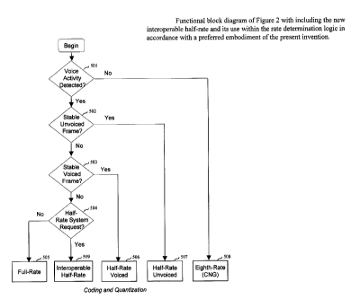
Figure 2 depicts a preferred embodiment of a variable bit rate coding
configuration including a rate determination logic that controls four coding
bit
rates. In this particular embodiment, the bit rate set comprises a dedicated
codec
type for non-active speech frames (block 508), unvoiced speech frames (block
507), stable voiced frames (block 506), and other types of frames (block 505).
The rate determination logic is based on signal classification done in
three steps in logic blocks 501, 502, and 503, whose operation is well known
to
the experts on prior art. First, a voice activity detector (VAD), block 501,
discriminates between active and inactive speech frames. If an inactive speech
frame is detected (background noise signal) then the classification chain ends
and
the frame is encoded in module 508 as an eighth-rate frame with comfort noise
generation (CNG) at the decoder (1.0 kbit/s according to CDMA2000 Rate Set
II).
If an active speech frame is detected, the frame is subjected to a second
classifier
502 dedicated to making a voicing decision. If the classifier 502 classifies
the
frame as unvoiced speech signal, the classification chain ends, and the frame
is
encoded in module 507 with a half rate optimized for unvoiced signals (6.2
kbit/s
according to CDMA2000 Rate Set II). Otherwise, the speech frame is passed
through to the "stable voiced" classification module 503. If the frame is
classified
as stable voiced frame, then the frame is encoded in module 506 with a half
rate
optimized for stable voiced signals (6.2 kbit/s according to CDMA2000 Rate Set
II). Otherwise, the frame is likely to contain a nonstationary speech segment
such
as a voiced onset or rapidly evolving voiced speech signal. These frames
typically
require a high bit rate for sustaining good subjective quality. Thus, in this
case, the
speech frame is encoded in module 505 as a full-rate frame (13.3 kbit/s
according
to CDMA2000 Rate Set II).
CA 02392640 2002-07-05
7
The classification modules 501, 502, and 503 are well-known to people
skilled in the art and will not be detailed in this invention. According to a
preferred
embodiment of the present invention, the coding modules at different bit rates
in
modules 505, 506, and 507 are based on code-excited linear prediction (CELP)
coding techniques well known in prior art. In this preferred embodiment, the
bit
rates are set according of Rate Set II of the CDMA2000 system described above.
In this preferred embodiment, the disclosed invention is explained based
on a wideband speech codec that has been standardized by the International
Telecommunications Union (ITU) as Recommendation 6.722.2 and known as the
AMR-WB codec (Adaptive Multi-Rate Wideband codec) [ 1 ]. This codec has also
been selected by the third generation partnership project (3GPP) for wideband
telephony in third generation wireless systems [2]. AMR-WB can operate at 9
bit
rates from 6.6 to 23.85 kbit/s. Here, the bit rate at 12.65 kbitls is used as
the full-
rate to illustrate the present invention.
In full-rate, the AMR-WB standard codec at 12.65 kbit/s is used with the
bit allocation given in Table 1. The use of the 12.65 kbit/s rate of the AMR-
WB
codec enables the design of a variable bit rate codec for the CDMA2000 system
capable of interoperating with other systems using the AMR-WB codec standard.
Extra 13 bits are added to fit in the 13.3 kbit/s full-rate of CDMA2000 Rate
Set II.
These bits are used to improve the codec robustness in case of erased frames.
More details about the AMR-WB codec can be found in reference [1]. The codec
is based on the algebraic code-excited linear prediction (ACELP) model
optimized
for wideband signals. It operates on 20 ms speech frames with a sampling
frequency of 16 kHz. The LP filter parameters are encoded once per frame using
46 bits. Then the frame is divided into four subframes where adaptive and
fixed
codebook indices and gains are encoded once per frame. The fixed codebook is
constructed using an algebraic codebook structure where the 64 positions in a
subframe are divided into 4 tracks of interleaved positions and where 2 signed
pulses are placed in each track. The two pulses per track are encoded using 9
bits
giving a total of 36 bits per subframe.
CA 02392640 2002-07-05
g
Table 1. Bit allocation of the 13.3 kbit/s full-rate in accordance with
the AMR-WB standard at 12.65 kbit/s (20 ms frames comprising four subframes).
In case of stable voiced frames, the half rate voiced coding module 506 is
used. The half rate voiced bit allocation is given in Table 2. Since the
frames to be
coded in this mode are characteristically very periodic, a substantially lower
bit
rate suffices for sustaining good subjective quality compared for instance to
transition frames. Signal modification is used which allows efficient coding
of the
delay information using only nine bits per 20-ms frame saving a considerable
proportion of the bit budget for other parameters. In signal modification, the
signal
is forced to follow a certain pitch contour that can be transmitted with 9
bits per
frame. Good performance of long term prediction allows to use only 13 bits per
5-
ms subframe for the fixed-codebook excitation without sacrificing the
subjective
speech quality. The fixed-codebook is an algebraic codebook comprises one
track
with two pulses, both having 64 possible positions. One bit is used to
indicate that
the frame is half rate voiced.
Table 2. Bit allocation of the half rate voiced at 6.2 kbit/s
for a 20-ms frame comprising four subframes.
LP Parameters 34
Pitch Delay 9
Pitch Filtering 4 - 1 + 1 + 1 + 1
Gains 24 = 6 + 6 + 6 + 6
Algebraic Codebook 52 = 13 + 13 + 13 + 13
Mode Bit 1
CA 02392640 2002-07-05
9
In case of unvoiced frames, the adaptive codebook (or pitch codebook) is
not used. A 13-bit Gaussian codebook is used in each subframe where the
codebook gain is encoded with 6 bits per subframe. 2 bits are used for the
half rate
mode: the first bit to indicate that the half rate is not stable voiced and
the second
bit to indicate it is stable unvoiced and not interoperable half rate (the
interoperable half rate will be explained in the next section
Table 3. Bit allocation of the half rate unvoiced at 6.2 kbitls
for a 20-ms frame comprising four subframes.
The eighth-rate is used to encode inactive speech frames (silence or
background noise). In this case only the LP filter parameters are encoded with
14
bits per frame and a gain is encoded with 6 bits per frame. These parameters
are
used for comfort noise generation (CNG) at the decoder.
Table 4. Bit allocation of the eighth-rate at 1.0 kbitls
for a 20-ms frame.
LP Parameters 14
Gain 6
CA 02392640 2002-07-05
1~
System-imposed half rate operation
In CDMA systems, the system can impose the use of the half rate instead
of full-rate in some speech frames in order to send in-band signaling
information.
This referred to as dim-and-burst signaling. The use of half rate as a maximum
bit
rate can be also imposed by the system during bad channel conditions (such as
near the cell boundaries) in order to improve the codec robustness. This is
referred
to as half rate max. In the VBR coding configuration described above, the half
rate
is used when the frame is stationary voiced or stationary unvoiced. Full-rate
is
used for onset, transient frames, and mixed voiced When the rate-selection
module chooses the frame to be encoded as a full-rate frame and the system
imposes the half rate frame the speech performance is degraded since the half
rate
modes are not capable of efficiently encoding onsets and transient signals.
Further, in a cross-system tandem free operation call between
CDMA2000 using the VBR Rate Set II solution based on AMR-WB and another
system using the standard AMR-WB, a case will arise where the CDMA2000
system will force the use of the half rate as explained earlier (such as in
dim-and-
burst signaling). Since the AMR-WB codec doesn't recognize the 6.2 kbit/s half
rate of the CDMA2000 wideband codec, then forced half rate frames will be
interpreted as erased frames. This will affect the performance of the
connection.
In this invention, a novel technique is disclosed which improves the
performance of variable bit rate speech codecs operating in CDMA wireless
systems in situations where the half rate is imposed by the system. Futher,
the
disclosed technique improves the performance in case of a cross-system tandem
free operation between CDMA2000 and other systems using AMR-WB codec
when the CDMA2000 system forces the use of the half rate.
In dim-and-burst signaling or half rate max operation, when the system
requests the use of half rate while a full-rate has been used by the
classification
mechanism, this indicates that the frame is not unvoiced nor stable voiced and
the
frame is likely to contain a nonstationary speech segment such as a voiced
onset or
rapidly evolving voiced speech signal. Thus the use of half rate optimized for
unvoiced or stable voiced signals will degrade the speech performance. A new
half rate mode is needed in this case, however, there are not enough bits to
CA 02392640 2002-07-05
11
maintain good quality in case of such nonstationary signals. Thus designing a
half
rate mode for these signals will not guarantee good performance and it will
likely
increase the memory requirements. In this invention, we disclose the use of a
half
rate mode directly derived from the full rate mode by dropping the fixed
codebook
indices after the frame has been encoded as a full rate frame. At the decoder
side,
the fixed codebook indices can be randomly generated and the decoder will
operate as if it is in full-rate. This half rate mode is referred to as
interoperable
half rate since both encoding and decoding are performed in full-rate. The bit
allocation of the interoperable half rate mode in accordance to a preferred
embodiment of the present invention is given in Table 5. In this preferred
embodiment, the full-rate is based on the AMR-WB standard at 12.65 kbitls, and
the half rate is derived by dropping the 144 bits needed for the indices of
the
algebraic fixed codebook. 2 bits are added for the half rate mode: the first
bit to
indicate that the half rate is not stable voiced and the second bit to
indicate it is
interoperable half rate and not unvoiced.
Table 5. Bit allocation of the interoperable half rate at 6.2 kbit/s compared
to the
full-rate (20 ms frames comprising four subframes).
Figure 3 depicts the functional block diagram of Figure 2 by adding the
new interoperable half rate mode and the it shows its use withing the rate
determination logic in accordance with a preferred embodiment of the present
invention. At the end of the rate determination chain, module 504 verifies if
a half
rate system request is present. If the rate determination logic indicates that
the
frame is active speech frame, and it is not unvoiced nor stable voiced, but
the
system requests a half rate operation, then the interoperable half rate mode
is used
CA 02392640 2002-07-05
12
and the frame is encoded in module 509 as a full-rate frame then the indices
of the
fixed codebook are dropped in order to obtain a half rate frame (6.2 kbitls
according to CDMA2000 Rate Set II). Otherwise (no half rate system request is
present) the speech frame is encoded in module 505 as a full-rate frame (13.3
kbit/s according to CDMA2000 Rate Set II).
Figure 4 shows an alternative approach to implement the interoperable
half rate operation. Here, the rate determination logic and variable rate
coding is
initially the same as in Figure 2. However, after a full-rate frame has been
encoded, a test is performed to verify if the system requests a half rate
operation.
If this is the case then the fixed codebook indices are dropped in order to
obtain an
interoperable half rate frame. Note that in this preferred embodiment, two
bits are
used for the half rate mode (stable voiced, unvoiced, or interoperable). Thus,
the
two bits indicating a half rate interoperable mode are added after the fixed
codebook indices are dropped.
In this preferred embodiment, in interoperable half rate operation at the
encoder side, the encoder operates as a full rate encoder. The fixed codebook
search is performed as usual and the determined fixed codebook excitation is
used
in updating the adaptive codebook content and filter memories for next frames
according to AMR-WB standard at 12.65 kbit/s [I], [2]. Therefore, no random
codebook indices are used within the encoder operation. This is evident in the
implementation of Figure 4 where the half rate system request is verified
after the
frame has been encoded in normal full-rate operation.
In interoperable half rate operation at the decoder side, the indices of the
fixed codebook are randomly generated. The decoder then operates as in full-
rate
operation. Other methods for generating the missed indices can be used. For
instance, the indices can be obtained by copying parts of the received
bitstream.
Note that a mismatch can happen between the memories at the encoder and
decoder side, since the fixed codebook excitation is not the same. However,
such
mismatch didn't seem to impact the performance especially in case of dim-and-
burst signaling where typical rates are around 2%. The encoder and decoder
operation can be synchronized if needed by using the same indices generated at
the decoder to update the memory at the encoder side. Note that the index
generation mechanism should be the same at the encoder and decoder and this is
CA 02392640 2002-07-05
13
only possible within a CDMA2000 call. This approach can be incorporated in the
implementation of Figure 3.
The performance of the proposed approach in dim-and-burst operation is
almost transparent compared to the case where there is no half rate system
request.
In lots of cases, the rate determination logic already determines the frame to
be
encoded with either quarter rate, half rate voiced, or half rate unvoiced. In
such a
case, the system request is neglected since it is already accommodated by the
encoder and the type of signal in the frame is suitable for encoding at a half
rate or
a lower rate. The interoperable half rate is used only when the rate
determination
logic chooses a full-rate frame and the system requests half rate operation.
With
typical dim-and-burst signaling rates (less than 2%) the actual percentage of
frames classified as full rate and forced to operate in half rate is much
lower. In
half rate max operation, the use of interoperable half rate is more frequent,
however, it is much better than using either half rate voiced or half rate
unvoiced
in case of nonstationary frames.
It should be noted that the classification logic is adaptive with a mode of
operation. Therefore in order to improve the performance, in the half rate-max
mode and dim-and-burst signaling, the logic can be made more relaxed for using
the specific half rate codecs (the half rate voiced and unvoiced are used
relatively
more often than in normal operation). This is a sort of extension to the multi-
mode
operation, where the logic is more relaxed modes with lower average data
rates.
Tandem free operation between CDMA2000 system and other
systems using the AMR-WB standard
As mentioned earlier, designing a variable bit rate wideband (VBR-WB)
codec for the CDMA2000 system based on the AMR-WB codec has the advantage
of enabling tandem free operation (TFO) between the CDMA2000 system and
other systems using the AMR-WB standard (such as the mobile GSM system or
W-CDMA third generation wireless system). However, in a cross-system tandem
free operation call between CDMA2000 and another system using AMR-WB, a
case will arise where the CDAM2000 system with force the use of the half rate
as
explained earlier (such as in dim-and-burst signaling). Since the AMR-WB codec
doesn't recognize the 6.2 kbit/s half rate of the CDMA2000 wideband codec,
then
CA 02392640 2002-07-05
14
forced half rate frames will be interpreted as erased frames. This will affect
the
performance of the connection. The use of the interoperable half rate mode
disclosed earlier will significantly improve the performance since this mode
can
interoperate with the 12.65 kbit/s rate of the AMR-WB standard.
As disclosed above, the interoperable half rate is basically a pseudo full-
rate, where the codec operates as if it is in the full-rate mode. The
difference is that
the algebraic codebook indices are dropped at the end and are not transmitted.
At
the decoder side, the indices are randomly generated and then the decoder
operates
as if it is in a full-rate mode.
Figure 5 illustrates a TFO configuration demonstrating the use of the
interoperable half rate mode during in-band transmission of signalling
information
(i.e., dim and burst condition) in CDMA2000 system side. In this figure, the
other
side is a system using the AMR-WB standard and a 3GPP wireless system is given
as an example.
In the link with the direction from CDMA2000 to 3 GPP, when the
multiplex sub-layer indicates a request for half rate mode, the VBR-WB codec
will operate in the interoperable half rate (I-HR) described earlier. At the
system
interface, when an I-HR frame is received, randomly generated algebraic
codebook indices are added to the bit stream to output a 12.65 kbit/s rate.
The
decoder at the 3GPP side will interpret it as an ordinary 12.65 kbit/s frame.
In the other direction, that is in a link from 3GPP to CDMA2000, if at the
system interface a half rate request is received, then the algebraic codebook
indices are dropped and two bits indicating the I-HR frame type are added. The
decoder at the CDMA2000 side will operate as an I-HR frame type, which is part
of the VBR-WB solution.
This proposal requires a minimal logic at the system interface and it
significantly improves the performance over forcing dim-and-burst frames as
blank-and-burst frames (erased frames).
Of course, many other modifications and variations are possible to the
disclosed invention. In view of the above detailed description of the present
CA 02392640 2002-07-05
15
invention and associated drawings, such other modifications and variations
will
now become apparent to those skilled in the art. It should also be apparent
that
such other variations may be effected without departing from the spirit and
scope
of the present invention. As an example, the fixed codebook indices are
dropped in
order to obtain an interoperable half rate frame, however, other bits with
less bit
error sensitivity can be dropped for this purpose.
REFERENCES
[ 1 ] ITU-T Recommendation 6.722.2 "Wideband coding of speech at around 16
kbit/s using Adaptive Multi-Rate Wideband (AMR-WB)", Geneva, 2002.
[2] 3GPP TS 26.190, "AMR Wideband Speech Codec: Transcoding Functions,"
3GPP Technical Specification.
Appendiz: Overview of the AMR-WB codec
Overview of AMR-WB encoder
The sampled speech signal is encoded on a block by block basis by
the encoding device 100 of Figure 6 which is broken down into eleven modules
numbered from 101 to 111.
The input speech is processed into the above mentioned L-sample
blocks called frames.
Referring to Figure 6, the sampled input speech signal 114 is down-
sampled in a down-sampling module 101. The signal is down-sampled from 16
kHz down to 12.8 kHz, using techniques well known to those of ordinary skill
in
the art. Down-sampling increases the coding efficiency, since a smaller
frequency
bandwidth is encoded. This also reduces the algorithmic complexity since the
CA 02392640 2002-07-05
16
number of samples in a frame is decreased. After down-sampling, the 320-sample
frame of 20 ms is reduced to 256-sample frame (down-sampling ratio of 4/5).
The input frame is then supplied to the optional pre-processing
block 102. Pre-processing block 102 may consist of a high-pass filter with a
50
Hz cut-off frequency. High-pass filter 102 removes the unwanted sound
components below SO Hz.
The down-sampled pre-processed signal is denoted by sp(n), n=0, 1,
2, ...,L-l, where L is the length of the frame (256 at a sampling frequency of
12.8
kHz). In a preferred embodiment of the preemphasis filter 103, the signal
sp(n) is
preemphasized using a filter having the following transfer function:
p~Z)-1_~Z-i
where w is a preemphasis factor with a value located between 0 and
1 (a typical value is ~ = 0.7). The function of the preemphasis filter 103 is
to
enhance the high frequency contents of the input signal. It also reduces the
dynamic range of the input speech signal, which renders it more suitable for
fixed-
point implementation. Preemphasis also plays an important role in achieving a
proper overall perceptual weighting of the quantization error, which
contributes to
improved sound quality. This will be explained in more detail herein below.
The output of the preemphasis filter 103 is denoted s(n). This
signal is used for performing LP analysis in calculator module 104. LP
analysis is
a technique well known to those of ordinary skill in the art. In this
preferred
embodiment, the autocorrelation approach is used. In the autocorrelation
approach, the signal s(n) is first windowed using with typically a Hamming
window having usually a length of the order of 30-40 ms. The autocorrelations
are computed from the windowed signal, and Levinson-Durbin recursion is used
to
CA 02392640 2002-07-05
17
compute LP filter coefficients, a;, where i=1,...,p, and where p is the LP
order,
which is typically 16 in wideband coding. The parameters a; are the
coefficients
of the transfer function of the LP filter, which is given by the following
relation:
P
A~z~ =1+~a; Z i
i=l
LP analysis is performed in calculator module 104, which also
performs the quantization and interpolation of the LP filter coefficients. The
LP
filter coefficients are first transformed into another equivalent domain more
suitable for quantization and interpolation purposes. The line spectral pair
(LSP)
and immitance spectral pair (ISP) domains are two domains in which
quantization
and interpolation can be efficiently performed. The 16 LP filter coefficients,
a"
can be quantized in the order of 30 to 50 bits using split or multi-stage
quantization, or a combination thereof. The purpose of the interpolation is to
enable updating the LP filter coefficients every subframe while transmitting
them
once every frame, which improves the encoder performance without increasing
the
bit rate. Quantization and interpolation of the LP filter coefficients is
believed to
be otherwise well known to those of ordinary skill in the art and,
accordingly, will
not be further described in the present specification.
The following paragraphs will describe the rest of the coding
operations performed on a subframe basis. In this embodiment, the input frame
is
divided into 4 subframes of 5 ms (64 samples at 12.8 kHz sampling). In the
following description, the filter A(z) denotes the unquantized interpolated LP
filter
of the subframe, and the filter A(z) denotes the quantized interpolated LP
filter of
the subframe.
In analysis-by-synthesis encoders, the optimum pitch and
innovation parameters are searched by minimizing the mean squared error
between the input speech and synthesized speech in a perceptually weighted
CA 02392640 2002-07-05
I8
domain. The weighted signal sw(n) is computed in a perceptual weighting filter
105. A perceptual weighting filter 105 with fixed denominator, suited for
wideband signals, is used. An example of transfer function for the perceptual
weighting filter 104 is given by the following relation:
W(z)=A(zly,)l(1-Yzz') where ~~Yz~YW I
In order to simplify the pitch analysis, an open-loop pitch lag ToL is
first estimated in the open-loop pitch search module 106 using the weighted
speech signal sw(n). Then the closed-loop pitch analysis, which is performed
in
closed-loop pitch search module 107 on a subframe basis, is restricted around
the
open-loop pitch lag ToL which significantly reduces the search complexity of
the
LTP parameters T and b (pitch lag and pitch gain). Open-loop pitch analysis is
usually performed in module 106 once every 10 ms (two subframes) using
techniques well known to those of ordinary skill in the art.
The target vector x for LTP (Long Term Prediction) analysis is first
computed. This is usually done by subtracting the zero-input response so of
weighted synthesis filter W(z~A(z) from the weighted speech signal sw(n). This
zero-input response so is calculated by a zero-input response calculator 108.
This
operation is well known to those of ordinary skill in the art and,
accordingly, will
not be further described.
A N dimensional impulse response vector h of the weighted
synthesis filter W(z)lA(z) is computed in the impulse response generator 109
using
the LP filter coefficients A(z) and A(z) from module 104. Again, this
operation is
well known to those of ordinary skill in the art and, accordingly, will not be
further described in the present specification.
CA 02392640 2002-07-05
19
The closed-loop pitch (or pitch codebook) parameters b, T and j are
computed in the closed-loop pitch search module 107, which uses the target
vector
x, the impulse response vector h and the open-loop pitch lag ToL as inputs.
The pitch search consists of finding the best pitch lag T and gain b that
minimize the mean squared weighted error E between the target vector z and the
scaled filtered past excitation.
In the preferred embodiment of the present invention, the pitch
(pitch codebook) search is composed of three stages.
In the first stage, an open-loop pitch lag ToL is estimated in open-
loop pitch search module 106 in response to the weighted speech signal sw(n).
As
indicated in the foregoing description, this open-loop pitch analysis is
usually
performed once every 10 ms (two subframes) using techniques well known to
those of ordinary skill in the art.
In the second stage, the search criterion C is searched in the closed-
loop pitch search module 107 for integer pitch lags around the estimated open-
loop pitch lag ToL (usually ~5), which significantly simplifies the search
procedure. A simple procedure is used for updating the filtered codevector yT
without the need to compute the convolution for every pitch lag.
Once an optimum integer pitch lag is found in the second stage, a
third stage of the search (module 107) tests the fractions around that optimum
integer pitch lag (AMR-WB standard uses '/4 and '/2 subsample resolution).
In wideband signals, the harmonic structure exists only up to a
certain frequency, depending on the speech segment. Thus, in order to achieve
efficient representation of the pitch contribution in voiced segments of
wideband
CA 02392640 2002-07-05
20
speech, the pitch prediction filter needs to have the flexibility of varying
the
amount of periodicity over the wideband spectrum. This is achieved by adding a
potential frequency shaping filters after the pitch predictor and select the
filter
that minimizes the mean-squared weighted error.
The pitch codebook index T is encoded and transmitted to
multiplexer 112. The pitch gain b is quantized and transmitted to multiplexer
112.
One extra bit is used to encode the index j of the selected frequency shaping
filter
in multiplexer 112.
Once the pitch, or LTP (Long Term Prediction) parameters b, T,
and j are determined, the next step is to search for the optimum innovative
excitation by means of search module 110 of Figure 6. First, the target vector
x is
updated by subtracting the LTP contribution:
X 2 X - byT
where b is the pitch gain and yT is the filtered pitch codebook vector (the
past excitation at delay T filtered with the selected low pass filter and
convolved
with the inpulse response h).
The search procedure in CELP is performed by finding the
optimum excitation codevector ck and gain g which minimize the mean-squared
error between the target vector and the scaled filtered codevector.
It is worth noting that the used innovation codebook is a dynamic
codebook consisting of an algebraic codebook followed by an adaptive prefilter
F(z) which enhances special spectral components in order to improve the
synthesis
speech quality, according to US Patent 5,444,816. In the preferred embodiment
of
the present invention, the innovative codebook search is performed in module
110
CA 02392640 2002-07-05
21
by means of an algebraic codebook as described in US patents Nos: 5,444,816
(Adoul et al.) issued on August 22, 1995; 5,699,482 granted to Adoul et al.,
on
December 17, 1997; 5,754,976 granted to Adoul et al., on May 19, 1998; and
5,701,392 (Adoul et al.) dated December 23, 1997.
Overview of AMR-WB Decoder
The speech decoding device 200 of Figure 7 illustrates the various
steps carried out between the digital input 222 (input stream to the
demultiplexer
217) and the output sampled speech 223 (output of the adder 221 ).
Demultiplexer 217 extracts the synthesis model parameters from
the binary information received from a digital input channel. From each
received
binary frame, the extracted parameters are:
- the short-term prediction parameters (STP) A(z) (once per frame);
- the long-term prediction (LTP) parameters T, b, and j (for each
subframe); and
- the innovation codebook index k and gain g (for each subframe).
The current speech signal is synthesized based on these parameters
as will be explained hereinbelow.
The innovative codebook 218 is responsive to the index k to
produce the innovation codevector ck, which is scaled by the decoded gain
factor g
through an amplifier 224. In the preferred embodiment, an innovative codebook
218 as described in the above mentioned US patent numbers 5,444,816;
CA 02392640 2002-07-05
22
5,699,482; 5,754,976; and 5,701,392 is used to represent the innovative
codevector ck .
The generated scaled codevector at the output of the amplifier 224
is processed through a frequency-dependent pitch enhancer 205.
Enhancing the periodicity of the excitation signal a improves the
quality in case of voiced segments. The periodicity enhancement is achieved by
filtering the innovative codevector ck from the innovative (fixed) codebook
through an innovation filter 205 (F(z)) whose frequency response emphasizes
the
higher frequencies more than lower frequencies. The coefficients of F(z) are
related to the amount of periodicity in the excitation signal u.
An efficient way to derive the filter F(z) coefficients used in a
preferred embodiment, is to relate them to the amount of pitch contribution in
the
total excitation signal u. This results in a frequency response depending on
the
subframe periodicity, where higher frequencies are more strongly emphasized
(stronger overall slope) for higher pitch gains. Innovation filter 205 has the
effect
of lowering the energy of the innovative codevector ck at low frequencies when
the excitation signal a is more periodic, which enhances the periodicity of
the
excitation signal a at lower frequencies more than higher frequencies.
Suggested
form for innovation filter 205 is
F(z)=-az+1-a z-1
where a is a periodicity factor derived from the level of periodicity
of the excitation signal u. The periodicity factor a is computed in the
voicing
factor generator 204. First, a voicing factor rv is computed in voicing factor
generator 204 by
CA 02392640 2002-07-05
23
rv = (E~ - Ec~ ~ (Ev + Ec~
where E~ is the energy of the scaled pitch codevector bvT and E~ is the
energy of the scaled innovative codevector gck. That is
N-I
Ev = b1 vr~ vT = b1 ~ vT (n)
n=0
and
N-l
Ec - g2 Ckr Ck - g2 ~ Ck (n)
n=0
Note that the value of r,, lies between -1 and 1 (1 corresponds to
purely voiced signals and -1 corresponds to purely unvoiced signals).
In this preferred embodiment, the factor a is then computed in
voicing factor generator 204 by
a=0.125(1+r,,)
which corresponds to a value of 0 for purely unvoiced signals and 0.25
for purely voiced signals.
The enhanced signal cf is therefore computed by filtering the scaled
innovative codevector gck through the innovation filter 205 (F(z)).
The enhanced excitation signal u' is computed by the adder 220 as:
CA 02392640 2002-07-05
24
u'=cf+bvT
Note that this process is not performed at the encoder 100. Thus, it
is essential to update the content of the pitch codebook 201 using the
excitation
signal a without enhancement to keep synchronism between the encoder 100 and
decoder 200. Therefore, the excitation signal a is used to update the memory
203
of the pitch codebook 201 and the enhanced excitation signal u' is used at the
input of the LP synthesis filter 206.
The synthesized signal s' is computed by filtering the enhanced
excitation signal u'through the LP synthesis filter 206 which has the form
1/A(z),
where A(z) is the interpolated LP filter in the current subframe. As can be
seen in
Figure 7, the quantized LP coefficients A(z) on line 225 from demultiplexer
217
are supplied to the LP synthesis filter 206 to adjust the parameters of the LP
synthesis filter 206 accordingly. The deemphasis filter 207 is the inverse of
the
preemphasis filter 103 of Figure 6. The transfer function of the deemphasis
filter
207 is given by
D(z)=1 ~(1-~z I)
where ~ is a preemphasis factor with a value located between 0 and 1 (a
typical value is ~ = 0.7). A higher-order filter could also be used.
The vector s' is filtered through the deemphasis filter D(z) (module
207) to obtain the vector s~ which is passed through the high-pass filter 208
to
remove the unwanted frequencies below 50 Hz and further obtain sh.
The over-sampling module 209 conducts the inverse process of the
down-sampling module 101 of Figure 6. In this preferred embodiment,
oversampling converts from the 12.8 kHz sampling rate to the original 16 kHz
CA 02392640 2002-07-05
sampling rate, using techniques well known to those of ordinary skill in the
art.
The oversampled synthesis signal is denoted s . Signal s is also referred to
as the
synthesized wideband intermediate signal.
The oversampled synthesis signal s" does not contain the higher
frequency components which were lost by the downsampling process (module 101
of Figure 6) at the encoder 100. This gives a low-pass perception to the
synthesized speech signal. To restore the full band of the original signal, a
high
frequency generation procedure is perform in modules 210 and requires input
from
voicing factor generator 204 (Figure 7).
The resulting band-pass filtered noise sequence z is added in adder
221 to the oversampled synthesized speech signal s" to obtain the final
reconstructed sound signal sour on the output 223.