Note: Descriptions are shown in the official language in which they were submitted.
CA 02392812 2004-12-03
' 678-894 (P10220)
APPARATUS AND METHOD FOR SYMBOL MAPPING TFCI BITS FOR
A HARD SPLIT MODE IN A CDMA MOBILE COMMUNICATION
SYSTEM
BACKGROUND OF THE INVENTION
1. Field of the Invention
The present invention relates generally to a transmission apparatus and
method for a hard split mode in a CDMA mobile communication system, and in
particular, to a mapping apparatus and method for transmitting TFCI (Transport
Format Combination Indicator) bits.
2. Description of the Related Art
In general, a downlink-shared channel (DSCH) is shared by a plurality of
users on a time-division basis. The DSCH is established in association with a
dedicated channel (DCH) for every user. The DCH is transmitted over a
CA 02392812 2002-07-08
678-894(P10220)
dedicated physical channel (DPCH), and the DPCH is constructed by combining
a dedicated physical control channel (DPCCH) and a dedicated physical data
channel (DPDCH) on a time-division basis.
The DSCH is transmitted over a physical downlink shared channel
(PDSCH), and channel control information for the PDSCH is transmitted over
DPCCH in the DPCH. The control information transmitted over the DPCCH
includes information on (i) TPC (Transmitted Power Control command) for
controlling uplink transmission power from a UE (User Equipment), (ii) Pilot
field used for channel variation estimation, transmission power measurement,
and slot synchronization acquisition from a Node B to a UE, and (iii) TFCI
(Transport Format Combination Indicator). Of this information, the TPC and the
Pilot are used as physical control information for the PDSCH and the DPCH, and
the TFCI is used to indicate information characteristics (e.g., information
transfer
rate, and combination of different information, i.e., combination of voice
information and packet information) of the data transmitted over the DSCH and
the DPDCH.
As stated above, the TFCI, the control information indicating
information characteristics of the data transmitted over the physical channels
DSCH and DPDCH, has a 10-bit length and is encoded into 32 bits. That is,
information on an amount of data is expressed with 10 bits, and the 10-bit
information is encoded into 32 bits to be transmitted over the physical
channel.
The TFCI is transmitted over the physical channel in the following
method specified in the 3GPP (3rd Generation Partnership Project) Technical
Specification 25.212 for the UMTS (Universal Mobile Telecommunication
System).
ak = k'" information bit of transport combination information (0 <_ k <_ 9)
-2-
CA 02392812 2002-07-08
678-894(P10220~
b~ = ith coded bit of transport combination information (0 <_ I <_ 31 )
dm = mph transmitted coded bit of transport combination information
The ak is 10-bit information indicating rate, type, and combination of the
data transmitted over the DPDCH, the bl is comprised of 32 coded bits obtained
by encoding the ak, and the d", is a transmitted coded bit where the b~ is
transmitted over the DPCCH. Here, the value m is variable according to
conditions.
Conditions for determining the number of d," bits are determined based
on a transmission mode of the DPCCH and a data rate of the DPCH. The
transmission mode of the DPCCH includes a normal transmission mode and a
compressed transmission mode. The compressed transmission mode is used
when a UE having one RF transceiver intends to measure at another frequency
band. An operation in the compressed transmission mode temporarily suspends
transmission at the current frequency band enabling the UE to measure at
another
frequency band. Data to be transmitted in the transmission suspended period is
compressed immediately before and after the transmission suspended period.
The "data rate of the DPCH", one of the conditions for determining the
number of dm bits, refers to a physical data rate of the DPCH and is
determined
according to a spreading factor (SF) of data. The SF ranges from 4 to 512 and
the
data rate ranges from 15 Kbps to 1920 Kbps. As the SF becomes higher, the data
rate becomes lower. The reason that the number of dm bits is determined
according to the data rate of the DPCH is because the size (or length) of the
TFCI
field transmitting TFCI bits of the DPCCH is variable according to the data
rate
of the DPCH.
The number of d", bits transmitted for each of the conditions for
CA 02392812 2002-07-08
678-894(P102201
determining d," is calculated as follows.
A 1. Normal transmission mode, data rate of DPCH being lower than 60
Kbns
S In a condition A 1 for determining the number of dm bits, the number of
dm bits becomes 30. In the 3GPP standard, a basic transmission unit of the
physical channel is a radio frame. The radio frame has a length of lOms and is
comprised of 15 time slots. Each time slot has fields for transmitting TFCI.
In
condition A1, each time slot has 2 TFCI transmission fields, so the number of
TFCI transmission code bits dm that can be transmitted for one radio frame
becomes 30. Therefore, although the number of the coded bits b, based on the
information bit ak becomes 32, the last two transport combination information
bits b3o and d3, are not transmitted due to a limitation in the number of the
TFCI
fields actually transmitted.
A2. Normal transmission mode, data rate of DPCH being_higher than 60
Kbus
In a condition A2 for determining the number of dm bits, a length of the
TFCI field in the time slot becomes $ bits, and the total number of dm that
can be
transmitted over the DPCCH for one radio frame becomes 120. When the total
number of dm is 120, b~ is repeatedly transmitted as follows.
~~0~~ ~ . .~ d31~b31~~ d32~0O ~ . .~ d63~31~, . . .~ d96~0O ~ . .~ d~19~b23~
In condition A2, 0'h to 23'd b~ bits are repeated 4 times, and 24'" to 31S' b~
bits are repeated 3 times for transmission.
A3. Compressed transmission mode, data rate of DPCH being lower than
60 Kbps or equal to 120 Kbps
-4-
CA 02392812 2002-07-08
678-894(P10220)
In a condition A3 for determining the number of d," bits, a length of the
TFCI field in the time slot becomes 4 bits, and the number of TFCIs that can
be
transmitted for one radio frame is variable according to the number of time
slots
used in the compressed transmission mode. In the compressed transmission
mode, the number of transmission-suspended time slots ranges from a minimum
of 1 to a maximum of 7, and the number of dm bits is between 32 and 56. The
number of the transmitted coded bits dm is limited to a maximum of 32, thereby
to transmit all of 0th to 31 S' b~ bits at the changed dm, and not transmit
the bl bits at
the other d",.
A4. Compressed transmission mode, data rate of DPCH being higher
than 120 Kbps or equal to 60 Kbps
In a condition A4 for determining the number of dm bits, a length of the
TFCI field in the time slot becomes 16 bits, and the number of TFCIs that can
be
transmitted for one radio frame is variable according to the number of time
slots
used in the compressed transmission mode. In the compressed transmission
mode, the number of transmission-suspended time slots ranges from a minimum
of 1 to a maximum of 7, and the number of d," bits ranges from 128 to 244. The
number of the transmitted coded bits dm is limited to a maximum of 128,
thereby
to repeatedly transmit 0th to 31 S' bl bits 4 times at the changed dm, and not
transmit the b~ bits at the other d",.
In the compressed transmission mode of conditions A3 and A4, the dm
bits are arranged in a period as far away from the transmission suspended
period
as possible to maximize reliability of transmitting the dm bits.
The conditions A1, A2, A3, and A4 are used when the TFCI indicates the
transport combination and type of the DPCH. A method of dividing the TFCI
into TFCI for DSCH and TFCI for DPCH during transmission can be divided
into two separate methods.
-5-
CA 02392812 2002-07-08
678-894(P10220)
A first method is for a hard split mode (HSM), and a second method is
for a logical split mode (LSM).
The TFCI for DCH will be referred to as TFCI(field 1 ) or a first TFCI,
and the TFCI for DSCH will be referred to as TFCI(field 2) or a second TFCI.
In the LSM method, the TFCI(field 1 ) and the TFCI(field 2), as one
TFCI, are encoded with a (32,10) sub-code of the second order Reed-Muller
code. The TFCI(field 1 ) and the TFCI(field 2) express 10-bit TFCI information
in various ratios, and the 10 information bits are encoded with one block
code,
i.e., (32,10) sub-code of the second order Reed-Muller code according to the
conditions A1, A2, A3, and A4, before being transmitted. The ratios of the
TFCI(field 1) to the TFCI(field 2) include 1:9, 2:8 3:7, 4:6, 5:5, 6:4, 7:3,
8:2, and
9:1. The sum of the first TFCI information bits and the second TFCI
information
bits may be less than 10. In the LSM, if the sum of the first TFCI information
bits
and the second TFCI information bits is less than 10, as many 0's as the
number
of the insufficient bits are inserted. As a result, the first TFCI information
bits
and the second TFCI information bits can be encoded with a (32,10) Reed-Muller
code before being transmitted.
In the HSM method, the TFCI(field 1) and the TFCI(field 2) are fixedly
expressed with 5 bits, respectively, and each information is output using a
(16,5)
bi-orthogonal code, and then the 16 bits for the TFCI(field 1 ) and the
TFCI(field
2) are alternately transmitted in accordance with the conditions Al, A2, A3,
and
A4. When the maximum number of the first TFCI information bits and the
maximum number of the second TFCI information bits are both limited to 5, if
the number of the first TFCI information bits or the second TFCI information
bits
exceeds 5, it is not possible to use the HSM method. Therefore, if the number
of
the first TFCI information bits or the second TFCI information bits is less
than 5,
CA 02392812 2002-07-08
678-894(P10220)
as many 0's as the number of empty bits are inserted before being encoded
using
a (16,5) bi-orthogonal code.
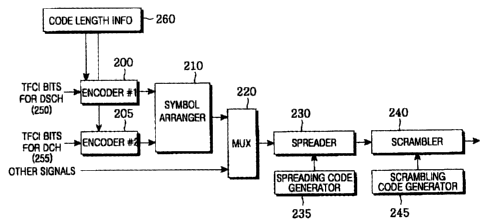
FIG. 1 illustrates a structure of a transmitter based on the conventional
HSM method. Refernng to FIG. 1, a (16,5) bi-orthogonal encoder 100 encodes a
5-bit TFCI(field 1 ) for the DCH into 16 coded symbols, and provides the 16
coded symbols to a rnultiplexer 110. At the same time, a (16,5) bi-orthogonal
encoder 105 encodes a 5-bit TFCI(field 2) for the DSCH into 16 coded symbols,
and provides the 16 coded symbols to the multiplexer 110. The multiplexer 110
then time-multiplexes the 16 coded symbols from the encoder 100 and the 16
coded symbols from the encoder 105, and outputs 32 symbols after arrangement.
A multiplexer 120 time-multiplexes the 32 symbols output from the multiplexer
110 and other signals, and provides its output to a spreader 130. The spreader
130
spreads the output signal of the multiplexer 120 with a spreading code
provided
from a spreading code generator 135. A scrambler 140 scrambles the spread
signal with a scrambling code provided from a scrambling code generator 145.
If a UE is located in a soft handover region, the LSM method is under
many restrictions for the following reasons. For convenience of explanation, a
brief description of a 3GPP wireless transmission network will be given. A RAN
(Radio Access Network) is comprised of a RNC (Radio Network Controller), a
Node B controlled by the RNC, and a UE (User Equipment). The RNC controls
the Node B, the Node B serves as a base station, and the UE serves as a
terminal.
The RNC can be divided into an SRNC (Serving Radio Network Controller) and
a CRNC (Control Radio Network Controller) according to the relationships with
the UE. The SRNC, an RNC where the UE is registered, processes data to be
transmitted to and received from the UE, and controls the UE. The CRNC, an
RNC where the UE is currently connected, connects the UE to the SRNC.
When Node Bs in communication with the UE belong to different RNCs,
CA 02392812 2002-07-08
678-894(P102201
the Node Bs not transmitting DSCH cannot recognize a value of the coded TFCI
bits for the DSCH, so it is not possible to correctly transmit coded TFCI bits
to
the UE.
In the above-stated HSM, the TFCI information bits for the DSCH and
the TFCI information bits for the DCH are independently encoded, so the UE has
no difficulty in decoding received TFCI bits. However, in the current 3GPP
HSM, the number of the TFCI bits for the DCH and the number of the TFCI bits
for the DSCH are both fixed to S bits to express 32 information bits.
Therefore,
when more TFCI bits for the DCH or the DSCH are needed, the HSM cannot be
used.
SUMMARY OF THE INVENTION
It is, therefore, an object of the present invention to provide an apparatus
and method for transmitting/receiving TFCI bits in a CDMA mobile
communication system.
It is another object of the present invention to provide an apparatus and
method for mapping coded TFCI symbols to a physical channel in a CDMA
mobile communication system.
It is further another object of the present invention to provide an
apparatus and method for mapping coded TFCI symbols for DCH and coded
TFCI symbols for DSCH, separated in a specific ratio, to a physical channel in
a
CDMA mobile communication system.
It is yet another object of the present invention to provide an apparatus
and method for receiving coded TFCI symbols mapped to a physical channel
before being transmitted in a CDMA mobile communication system.
-R-
CA 02392812 2004-12-03
It is still another object of the present invention to provide an apparatus
and method for receiving coded TFCI symbols for DCH and coded TFCI
symbols for DSCH, separated in a specific ratio, mapped to a physical channel
before being transmitted in a CDMA mobile communication system.
The present invention provides a method for mapping first coded TFCI
(Transport Format Combination Indicator) symbols and second coded TFCI symbols
to a frame in a mobile communication system for encoding k first TFCI bits and
(10-
k) second TFCI bits, where k is a variable integer with a value in the range
of from 1
<_ k _< 9, the method comprising the steps of multiplexing at least some of
the first and
second coded TFCI symbols to produce a combined output having an order of
symbols effected by the variable integer k, and mapping all or less than all
of the
multiplexed coded symbols to the frame to satisfy a number of the coded
symbols that
can be mapped to one frame.
The present invention also provides an apparatus for transmitting first TFCI
(Transport Format Combination Indicator) bits and second TFCI bits over a
frame in
a mobile communication system, where k is a variable integer with a value in
the
range of from 1 <_ k <_ 9, comprising at least one encoder for encoding k
first TFCI
bits at a first coding rate to output (3k+1) first coded TFCI symbols, and
encoding
(10-k) second TFCI bits at a second coding rate to output (31-3k) second coded
TFCI
symbols, and a coded symbol arranger for multiplexing at least some of the
coded
symbols to produce a combined output having an order of symbols effected by
the
variable integer k, and outputting all or less than all of the multiplexed
coded symbols
to satisfy a number of the coded symbols that can be mapped to one frame.
The present invention also provides a method for transmitting first TFCI
(Transport Format Combination Indicator) bits and second TFCI bits over a
frame in
a mobile communication system, where k is a variable integer with a value in
the
range of from 1 <_ k <_ 9, comprising the steps of encoding k first TFCI bits
to output
(3k+1) first coded TFCI symbols, encoding (10-k) second TFCI bits to output
(31-3k)
-9-
CA 02392812 2004-12-03
second coded TFCI symbols, multiplexing at least some of the first and second
coded
TFCI symbols to produce a combined output having an order of symbols effected
by
the variable integer k, and outputting all or less than all of the multiplexed
coded
symbols to satisfy a number of the coded symbols that can be mapped to one
frame.
In accordance with a first aspect of the present invention, there is
provided a method for mapping first coded TFCI symbols and second coded
TFCI symbols to a radio frame in a transmission apparatus of a mobile
communication system for encoding k first TFCI bits and (10-k) second TFCI
bits, a sum of the first coded TFCI symbols and the second coded TFCI symbols
being 32. The method comprises multiplexing the coded symbols such that the
first coded TFCI symbols and the second coded TFCI symbols are uniformly
distributed according to a transmission mode and a data rate of the radio
frame,
and outputting 32 coded symbols; and mapping the 32 multiplexed coded
symbols to the radio frame to satisfy the number of the coded symbols that can
be mapped to one radio frame, determined according to the transmission mode
and the data rate of the radio frame.
In accordance with a second aspect of the present invention, there is
provided an apparatus for transmitting first TFCI bits and second TFCI bits
over
a radio frame in a transmission apparatus of a mobile communication system.
The apparatus comprises at least one- encoder for encoding k first TFCI bits
at a
first coding rate to output (3k+1) first coded TFCI symbols, and encoding (10-
k)
second TFCI bits at a second coding rate to output (31-3k) second coded TFCI
symbols; and a coded symbol arranger for multiplexing the coded symbols such
that the first coded TFCI symbols and the second coded TFCI symbols are
uniformly distributed according to a transmission mode and a data rate of the
radio frame, and outputting the multiplexed coded symbols according to the
number of coded symbols that can be transmitted over one radio frame.
9a
CA 02392812 2002-07-08
678-894(P10220)
In accordance with a third aspect of the present invention, there is
provided a method for transmitting first TFCI bits and second TFCI bits over a
radio frame in a transmission apparatus of a mobile communication system. The
S method comprises encoding k first TFCI bits at a first coding rate to output
(3k+1) first coded TFCI symbols; encoding (10-k) second TFCI bits at a second
coding rate to output (31-3k) second coded TFCI symbols; a coded symbol
arranger for multiplexing the coded symbols such that the first coded TFCI
symbols and the second coded TFCI symbols are uniformly distributed according
to a transmission mode and a data rate of the radio frame; and outputting the
multiplexed coded symbols according to the number of coded symbols that can
be transmitted over one radio frame.
In accordance with a fourth aspect of the present invention, there is
provided an apparatus for decoding k first TFCI bits and ( 10-k) second TFCI
bits
in a reception apparatus of a mobile communication system for receiving (3k-1)
first coded TFCI symbols for a DCH (Dedicated Channel) and (31-3k) second
coded TFCI symbols for a DSCH (Downlink Shared Channel). The apparatus
comprises a coded symbol rearranger for separating the first coded TFCI
symbols
and the second coded TFCI symbols, transmitted over a DPCH (Dedicated
Physical Channel), according to a value of the k, for rearrangement; and at
least
one decoder for decoding the first coded TFCI symbols to output the k first
TFCI
bits, and decoding the second coded TFCI symbols to output the (10-k) second
TFCI bits.
In accordance with a fifth aspect of the present invention, there is
provided a method for decoding k first TFCI bits and (10-k) second TFCI bits
in
a reception apparatus of a mobile communication system for receiving (3k-1)
first coded TFCI symbols for a DCH (Dedicated Channel) and (31-3k) second
coded TFCI symbols for a DSCH (Downlink Shared Channel). The method
- ~n-
CA 02392812 2002-07-08
678-894~,P 10220
comprises separating the first coded TFCI symbols and the second coded TFCI
symbols, transmitted over a DPCH (Dedicated Physical Channel), according to a
value of the k, for rearrangement; and decoding the first coded TFCI symbols
to
output the k first TFCI bits; and decoding the second coded TFCI symbols to
S output the ( 10-k) second TFCI bits.
BRIEF DESCRIPTION OF THE DRAWINGS
The above and other objects, features and advantages of the present
invention will become more apparent from the following detailed description
when taken in conjunction with the accompanying drawings in which:
FIG. 1 illustrates a structure of a conventional transmitter based on a
hard split mode (HSM);
FIG. 2 illustrates a structure of a Node B transmitter according to an
embodiment of the present invention;
FIG. 3 illustrates another structure of a Node B transmitter according to
an embodiment of the present invention;
FIG. 4 illustrates a detailed structure of the encoder illustrated in FIGs. 2
and 3;
FIG. 5 illustrates a structure of a downlink radio frame transmitted from
a Node B to a UE;
FIG. 6 illustrates a detailed structure of the symbol arranger illustrated in
FIG. 2;
FIG. 7 illustrates a detailed structure of the selector illustrated in FIG. 3;
FIG. 8 illustrates another detailed structure of the symbol arranger
illustrated in FIG. 3;
FIG. 9 illustrates a structure of a UE receiver according to an
embodiment of the present invention;
FIG. 10 illustrates another structure of a UE receiver according to
another embodiment of the present invention;
_11_
CA 02392812 2002-07-08
678-894 tP10220~
FIG. 11 illustrates a detailed structure of the decoder used in the receiver
illustrated in FIG. 10;
FIG. 12 illustrates a method of selecting codes to be used for first TFCI
and second TFCI according to an embodiment of the present invention;
FIG. 13 illustrates another connection between encoders and a symbol
arranger according to an embodiment of the present invention;
FIG. 14 illustrates yet another connection between an encoder and a
symbol arranger according to an embodiment of the present invention;
FIG. 15 illustrates further another connection between an encoder and a
symbol arranger according to an embodiment of the present invention;
FIG. 16 illustrates an encoding operation according to an embodiment of
the present invention;
FIG. 17 illustrates a decoding operation according to an embodiment of
the present invention;
FIGS. 18A and 18B illustrate two different structures of a symbol
arranger according to an embodiment of the present invention; and
FIG. 19 illustrates a structure of a coded symbol arranger according to an
embodiment of the present invention.
DETAILED DESCRIPTION OF THE PREFERRED EMBODIMENT
A preferred embodiment of the present invention will be described herein
below with reference to the accompanying drawings. In the following
description, well-known functions or constructions are not described in detail
since they would obscure the invention in unnecessary detail.
The present invention provides an apparatus and method for dividing a
total of 10 input information bits into information bits for DCH and
information
bits for DSCH in a ratio of 1:9, 2:8, 3:7, 4:6, 5:5, 6:4, 7:3, 8:2, or 9:1 in
the HSM
method, and then separately encoding the information bits for the DCH and the
-12-
CA 02392812 2002-07-08
678-894(P10220)
information bits for the DSCH. If the sum of the number of first TFCI
information bits and the number of second TFCI information bits is less than
10,
the apparatus and method according to an embodiment of the present invention
increases reliability of the first TFCI information bits or the second TFCI
information bits before encoding. Alternatively, the apparatus and method
increases reliability of both the first TFCI information bits and the second
TFCI
information bits before encoding.
First, a description of an encoder will be made for when the sum of the
first TFCI information bits and the second TFCI information bits is 10.
One radio frame transmits 30, 120, 32, and 128 coded TFCI symbols
according to the conditions A1, A2, A3, and A4, respectively. In each case
excluding repeated transmission, a basic coding rate is 10/32, and in
condition
A1, a coding rate becomes 10/30 due to the limited transmission of the
physical
channel. Therefore, when the TFCI information bits for the DSCH and the TFCI
information bits for the DCH are divided in a specific ratio of 1:9, 2:8, 3:7,
4:6,
5:5, 6:4, 7:3, 8:2, or 9:1, it is natural to maintain the coding rate by
dividing the
coded symbols in the above ratios. Maintaining the coding rate means
maintaining a basic coding rate of (32,10). In the HSM, the reason for
maintaining a code gain of the differently encoded TFCI for the DSCH and TFCI
for the DCH is to maintain a code gain by similarly maintaining the coding
rate
of (32,10), although the TFCI for the DSCH and the TFCI for the DCH are
separately encoded. An example of dividing the coded bits according to the
ratio
of the input bits will be described on the assumption of the condition A1.
In condition A1, if 10 input information bits are divided in a 1:9 ratio,
then 30 coded output symbols are divided in a 3:27 ratio, and if the 10 input
information bits are divided in 2:8, then the 30 coded output symbols are
divided
in a 6:24 ratio. Further, if the 10 input information bits are divided in a
3:7 ratio,
_»_
CA 02392812 2002-07-08
678-894yPi0220)
then the 30 coded output symbols are divided in a 9:21 ratio, and if the 10
input
information bits are divided in a 4:6 ratio, then the 30 coded output symbols
are
divided in a 12:18 ratio. However, in conditions A2, A3, and A4, the 32 coded
symbols are all transmitted or the 32 coded symbols are repeatedly
transmitted,
so the coded symbols cannot be correctly divided as in the condition A I .
Therefore, in the embodiment of the present invention, the coding rates
of the coded symbols defined in association with the input bits can be
expressed
as shown in Table 1.
Table 1
Coding Rate
Ratio of Coded Used
Ratio of Input Coding Rate Coding Rate of
Bits Symbols of 1 St 2"t
TFCI TFCI
3:29 (3 :1 ) (29:9)
1:9 4:28 (4:1) (28:9)
5:27 (5:1 ) (27:9)
6:26 (6:2) (26:8)
2:8 7:25 (7:2) (25:8)
8:24 (8:2) (24:8)
9:23 (9:3) (23:7)
3:7 10:22 (10:3) (22:7)
11:21 (11:3) (21:7)
12:20 ( 12:4) (20:6)
4:6 13:19 (13:4) ( 19:6)
14:18 (14:4) (18:6)
18:14 (18:6) (14:4)
6:4 19:13 ( 19:6) ( I 3:4)
20:12 (20:6) ( 12:4)
- 14-
CA 02392812 2002-07-08
678-894 (P10220~
21:11 (21:7) ( 11:3)
7:3 22:10 (22:7) ( 10:3)
23:9 (23:7) (9:3)
24:8 (24:8) (8:2)
8:2 25:7 (25:8) (7:2)
26:6 (26:8) (6:2)
27:5 (27:9) (5:1 )
9:1 28:4 (28:9) (4:1 )
29:3 (29:9) (3:1 )
A criterion for determining the coding rates in Table 1 according to the
ratio of the input bits will be described herein below. The embodiment of the
present invention sets the sum of the coded symbols to 30 by applying the
minimum required value to the substantial coding rate (30,10) for the most
frequently used case A 1 among the conditions A 1, A2, A3, and A4, and setting
the coding rate of the first TFCI and the coding rate of the second TFCI to a
minimum of 1/3, and then allocates the remaining 2 coded symbols to the coded
symbol of the first TFCI and coded symbol of the second TFCI, respectively
Therefore, the embodiment of the present invention increases both the coding
rate of the first TFCI and the coding rate of the second TFCI, or increases
either
the coding rate of the first TFCI or the coding rate of the second TFCI, using
the
remaining 2 coded symbols as coded symbols of the first TFCI or coded symbols
of the second TFCI. The embodiment increases the coding rate of either the
first
TFCI or the second TFCI among the criteria for determining the coding rates,
when it is necessary to increase performance by increasing only the coding
rate
of the first TFCI or the coding rate of the second TFCI on a condition that
the
sum of the number of the coded symbols for the first TFCI and the number of
the
coded symbols for the second TFCI should become 32.
-1.5-
CA 02392812 2002-07-08
678-894 (P10220)
Once a ratio of the input bits in Table 1 is determined, one of 3 coding
methods is used according to the ratio of the coded symbols.
The present invention provides an encoder capable of performing
encoding at all the coding rates illustrate in Table 1. Referring to Table 1,
if a
ratio of the input bits (or a ratio of information amounts, i.e., a ratio of
the first
TFCI bits and the second TFCI bits) is 1:9, a ratio of the coded symbols
becomes
3:29, 4:28, or 5:27. If the ratio of the input bits is 2:8, the ratio of the
coded
symbols becomes 6:26, 7:25, or 8:24, and if the ratio of the input bits is
3:7, the
ratio of the coded symbols becomes 9:23, 10:22, or 11:21. If the ratio of the
input
bits is 4:6, the ratio of the coded symbols becomes 12:20, 13:19, or 14:18. If
the
ratio of the input bits is 6:4, the ratio of the coded symbols becomes 18:14,
19:13, or 20:12, and if the ratio of the input bits is 7:3, the ratio of the
coded
symbols becomes 21:11, 22:10, or 23:9. If the ratio of the input bits is 8:2,
the
ratio of the coded symbols becomes 24:8, 25:7, or 26:6, and if the ratio of
the
input bits is 9:1, the ratio of the coded symbols becomes 27:5, 28:4, or 29:3.
Therefore, if the ratio of input bits is 1:9, then {(3,1) encoder, (29,9)
encoder, (4,1 ) encoder, and (28,9) encoder} or { (S,1 ) encoder and (27,9)
encoder} are required. If the ratio of input bits is 2:8, then {(6,2) encoder,
(26,8)
encoder, (7,2) encoder, and (25,8) encoder} or {(8,2) encoder and (24,8)
encoder} are required. If the ratio of input bits is 3:7, then {(9,3) encoder,
(23,7)
encoder, (10,3) encoder, and (22,7) encoder} or {(11,3) encoder and (21,7)
encoder} are required. If the ratio of input bits is 4:6, then {(12,4)
encoder, (20,6)
encoder, (13,4) encoder, and (19,6) encoder} or {(14,4) encoder and (18,6)
encoder} are required. Therefore, considering the 24 encoders and the
currently
used (16,5) encoder, and (32,10) encoder, there is a need for an encoder
capable
of serving as the 18 encoders with a single structure in order to increase
performance and reduce the hardware complexity.
CA 02392812 2004-12-03
In general, Hamming distance distribution for codewords of the error
correcting codes can serve as a measure indicating the performance of linear
error correcting codes. The "Hamming distance" means the number of non-zero
symbols in a codeword. That is, for a certain codeword '0111', the number of
1's
included in the codeword is 3, so the Hamming distance is 3. The smallest
value
among the Hamming distance values is called a "minimum distance dm;"", and an
increase in the minimum distance of the codeword improves the error correcting
performance of the error correcting codes. In other words, the "optimal code"
means a code having the optimal error correcting performance. This is
disclosed
in detail in a' book, The Theory of Error-Correcting Codes, F.J. MacWilliams,
N.J.A.
Sloane, Elsevier/North-Holland, 762 pp ( 1979).
In addition, in order to use a single encoder structure for the encoders
having different lengths for a reduction in the hardware complexity, it is
preferable to shorten the code with longest length, i.e., the (32,10) code.
For the
shortening, it is necessary to puncture the coded symbols. However, during the
puncturing, the minimum distance of the code varies according to the
puncturing
positions. Therefore, it is preferable to calculate the puncturing positions
such
that the punctured code has the minimum distance.
For example, in terms of the minimum distance, it is most preferable to
use an optimal (7,2) code having one of the coding rates illustrated in Table
1,
obtained by repeating a (3,2) simplex code 3 times and then puncturing the
last
two coded symbols. Table 2 illustrates the relationship between input
information
bits of the (3,2) simplex code and (3,2) simplex codewords output based on the
input information bits.
Table 2
Inut Information Bits (3,2) Sim lex Codewords
00 000
_ 17_
CA 02392812 2002-07-08
678-894(P1022U1
O1 101
Oll
11 110
Table 3 illustrates the relationship between the input information bits and
(7,2) simplex codewords obtained by repeating the (3,2) simplex codeword 3
times and then puncturing the last two coded symbols.
5
Table 3
Input Information (7,2) Simplex Codewords
Bits
00 000 000 0
Ol 101 101 1
10 011 Ol l 0
11 110 110 1
However, the (7,2) simplex codewords obtained by repeating the (3,2)
simplex codeword 3 times and then puncturing the last two coded symbols can be
10 implemented by shortening the existing (16,4) Reed-Muller code.
A description of the shortening method will first be made by way of
example. The (16,4) Reed-Muller code is a linear combination of 4 basis
codewords of length 16, where '4' is the number of input information bits.
Receiving only 2 bits among the 16 input information bits is equivalent to
using a
linear combination of only 2 basis codewords among the 4 basis codewords of
length 16 and not using the remaining codewords. In addition, by restricting
the
use of the basis codewords and then puncturing 9 symbols among 16 symbols, it
is possible to realize a (7,2) encoder using the (16,4) encoder. Table 4
illustrates
the shortening method.
Table 4
-1R-
CA 02392812 2002-07-08
678-894 (P10220'I
Input
Info Codewords
Bits
0000 0(*)0 0 0 0(*)0 0 0 0(*)0 0(*)of*)of*)of*)of*)of*)
0001 0(*)1 0 1 0(*)1 0 I 0(*)1 0(*)1(*)0(*)I(*)0(*)1(*)
0010 0(*)0 I 1 0(*)0 1 1 0(*)0 1(*)I(*)0(*)0(*)1(*)1(*)
0011 0(*)1 I 0 0(*)1 1 0 0(*)I 1(*)U(*)0(*)1(*)I(*)0(*)
0100 0 0 0 0 1 1 1 1 0 0 0 0 1 1 1 1
0101 0 I 0 1 1 0 1 0 0 1 0 1 1 0 1 0
0110 0 0 1 I 1 I 0 0 0 0 1 1 1 1 0 0
0111 0 1 1 0 1 0 0 1 . 1 1 0 1 0 0 1
0
1000 0 0 0 0 0 0 0 0 1 1 1 1 1 1 1 1
1001 0 1 0 1 0 1 0 1 1 0 I 0 1 0 1 0
1010 0 0 1 1 0 0 I 1 1 1 0 0 1 1 0 0
1011 0 1 1 0 0 I 1 0 1 0 0 I I 0 0 1
1100 0 0 0 0 1 I I 1 1 1 1 1 0 0 0 0
IIOI 0 1 0 I 1 0 1 0 1 0 1 0 0 1 0 1
1110 0 0 1 1 1 1 0 0 1 1 0 0 0 0 I 1
1111 0 1 1 0 1 0 0 1 1 0 0 1 0 1 1 0
Referring to Table 4, every ( 16,4) codeword is a linear combination of
the 4 bold basis codewords of length 16. In order to obtain the (6,2) code,
only
the upper 2 codewords among the 4 basis codewords are used. Then, the
remaining, lower 12 codewords are automatically unused. Therefore, only the
upper 4 codewords are used. Besides, in order to generate a basis codeword of
length 7 among the upper 4 basis codewords, it is necessary to puncture 9
symbols. It is possible to obtain the (7,2) simplex codewords of Table 3 by
puncturing the symbols indicated by (*) in Table 4 and then collecting the
remaining 7 coded symbols.
Herein, a description will be made of a structure of an encoder for
creating } (3,1 ) optimal code, (29,9) optimal code, (4,1 ) optimal code, and
(28,9)
optimal code} and {(5,1) optimal code and (27,9) optimal code} used for the
information bit ratio of 1:9, a structure of an encoder for creating {(6,2)
optimal
code, (26,8) optimal code, (7,2) optimal code and (25,8) optimal code} and
-19-
CA 02392812 2002-07-08
678-894 ~,P10220)
{(8,2) optimal code and (24,8) optimal code} used for the information bit
ratio of
2:8, a structure of an encoder for creating {(9,3) optimal code, (23,7)
optimal
code, (10,3) optimal code, and (22,7) optimal code} and {(11,3) optimal code
and (2I,7) optimal code} used for the information bit ratio of 3:7, a
structure of
S an encoder for creating { ( 12,4) optimal code, (20,6) optimal code, ( 13,4)
optimal
code, and (19,6) optimal code} and {(14,4) optimal code and (18,6) optimal
code} used for the information bit ratio of 4:6, and a structure of an encoder
for
creating a (16,5) optimal code and a (32,10) optimal code used for the
information bit ratio of 5: S, by shortening a (32,10) sub-code of the second
order
Reed-Muller code. In addition, a structure of a decoder corresponding to the
encoder will also be described herein below.
1. First Embodiment of Transmitter
An embodiment of the present invention provides an apparatus and
method for dividing 10 information bits in a ratio of I:9, 2:8, 3:T, 4:6, 5:5,
6:4,
7:3, 8:2, or 9:1 before coding in the hard split mode, as done in the logical
split
mode where the ratio of the input information bits is 5:5.
FIG. 2 illustrates a structure of a transmitter according to an embodiment
of the present invention. Referring to FIG. 2, TFCI bits for the DSCH and TFCI
bits for the DCH, divided in one of the above information bit ratios, are
provided
to first and second encoders 200 and 205, respectively. Here, the TFCI bits
for
the DSCH are referred to as TFCI(field 1) or first TFCI bits, while the TFCI
bits
for the DCH are referred to as TFCI(field 2) or second TFCI bits. The TFCI
bits
for the DSCH are generated from a first TFCI bit generator 250, and the TFCI
bits for the DCH are generated from a second TFCI bit generator 255. The
number of the first TFCI bits is different from the number of the second TFCI
bits according to the above information bit ratios. In addition, a control
signal
indicating code length information, i.e., information on a length value of the
codeword set according to the information bit ratio, is provided to the first
and
-2~-
CA 02392812 2002-07-08
678-894 (P102201
second encoders 200 and 205. The code length information is generated from a
code length information generator 260, and has a value variable according to
lengths of the first TFCI bits and the second TFCI bits.
When the information bit ratio is 6:4, the encoder 200 receives a length
control signal for allowing the encoder 200 to serve as a (20,6) encoder, a
(19,6)
encoder, or an (18,6) encoder upon receipt of 6 TFCI bits for the DSCH, and
serves as one of the 3 coders, while the encoder 205 receives a length control
signal for allowing the encoder 205 to serve as a ( 12,4) encoder, a ( 13,4)
encoder,
or a (14,4) encoder upon receipt of 4 TFCI bits for the DCH, and serves as one
of
the 3 coders. When the information bit ratio is 7:3, the encoder 200 receives
a
length control signal for allowing the encoder 200 to serve as a (23,7)
encoder, a
(22,7) encoder, or a (21,7) encoder upon receipt of 7 TFCI bits for the DSCH,
and serves as one of the 3 coders, while the encoder 205 receives a length
control
signal for allowing the encoder 205 to serve as a (9,3) encoder, a (10,3)
encoder,
or an (11,3) encoder upon receipt of 3 TFCI bits for the DCH, and serves as
one
of the 3 coders. When the information bit ratio is 8:2, the encoder 200
receives a
length control signal for allowing the encoder 200 to serve as a (26,8)
encoder, a
(25,8) encoder, or a (24,8) encoder upon receipt of 8 TFCI bits for the DSCH,
and serves as one of the 3 coders, while the encoder 205 receives a length
control
signal for allowing the encoder 205 to serve as a (6,2) encoder, a (7,2)
encoder,
or an (8,2) encoder upon receipt of 2 TFCI bits for the DCH, and serves as one
of
the 3 coders. When the information bit ratio is 9:1, the encoder 200 receives
a
length control signal for allowing the encoder 200 to serve as a (29,9)
encoder, a
(28,9) encoder, or a (27,9) encoder upon receipt of 9 TFCI bits for the DSCH,
and serves as one of the 3 coders, while the encoder 205 receives a length
control
signal for allowing the encoder 205 to serve as a (3,1 ) encoder, a (4,1 )
encoder,
or a (S,1 ) encoder upon receipt of 1 TFCI bits for the DCH, and serves as one
of
the 3 coders. The length control signal should be generated such that the sum
of
the first TFCI bits and the second TFCI bits becomes 32. That is, if the first
TFCI
-21 -
CA 02392812 2002-07-08
678-894(P1022U)
encoder is a (4,1) encoder, the second TFCI encoder should be a (28,9) encoder
rather than a (29,9) encoder or a (27,9) encoder. If the second TFCI encoder
becomes the (29,9) encoder, the number of coded bits bl becomes 33, and if the
second TFCI encoder becomes the (27,9) encoder, the number of coded bits b~
becomes 31. In this case, the transmitter is not compatible with the
conventional
transmitter that uses two ( 16,5) encoders or a (32,10) encoder. In addition,
the
transmitter is not compatible with the conventional transmitter in mapping the
b~
bits to the dm bits.
FIG. 4 illustrates a detailed structure of the encoders 200 and 205. That
is, the encoder 200 for encoding the first TFCI encoder and the encoder 205
for
encoding the second TFCI encoder have the structure of FIG. 4. However, when
generating the first TFCI codewords and the second TFCI codewords with a time
delay, the first TFCI encoder and the second TFCI encoder can be realized with
a
single encoder. A structure of a transmitter for generating the first TFCI
codewords and the second TFCI codewords with a time delay is illustrated in
FIG. 3.
First, with reference to FIG. 2, a detailed description of an encoder
according to the present invention will be made for the case where the ratio
of the
first TFCI bits to the second TFCI bits is 1:9.
When the information bit ratio is 1:9, the encoder 200 serves as a (3,1 )
encoder and the encoder 205 serves as a (29,9) encoder; the encoder 200 serves
as a (4,1 ) encoder and the encoder 205 serves as a (28,9) encoder; or the
encoder
200 serves as a (5,1) encoder and the encoder 205 serves as a (27,9) encoder.
Now, operations of the (3,1 ) encoder, the (29,9) encoder, the (4,1 )
encoder, the (28,9) encoder, the (5,1 ) encoder, and the (27,9) encoder will
be
described in detail with reference to FIG. 4.
-22-
CA 02392812 2002-07-08
678-894 ~P 1022
First, an operation of the (3,1 ) encoder will be described. Referring to
FIG. 4, one input bit a0 is normally provided to the encoder, and the
remaining
input bits al, a2, a3, a4, a5, a6, a7, a8, and a9 are all filled with '0'. The
input bit
a0 is applied to a multiplier 410, the input bit al to a multiplier 412, the
input bit
a2 to a multiplier 414, the input bit a3 to a multiplier 416, the input bit a4
to a
multiplier 418, the input bit a5 to a multiplier 420, the input bit a6 to a
multiplier
422, the input bit a7 to a multiplier 424, the input bit a8 to a multiplier
426, and
the input bit a9 to a multiplier 428. At the same time, a Walsh code generator
400
generates a basis codeword W 1 = 1 O 1 O 1 O 10101 O 1 O 110101 O 10101010100,
and
provides the generated basis codeword W 1 to the multiplier 410. The
multiplier
410 then multiplies the input bit a0 by the basis codeword W 1 in a symbol
unit,
and provides its output to an exclusive OR (XOR) operator 440. Further, the
Walsh code generator 400 generates other basis codewords W2, W4, W8, and
W 16, and provides them to the multiplier 412, 414, 416, and 418,
respectively.
An all-1's code generator 402 generates an all-1's basis codeword (or all-1's
sequence) and provides the generated all-1's basis codeword to the multiplier
420. A mask generator 404 generates basis codewords M1, M2, M4, and M8, and
provides the generated basis codewords M1, M2, M4, and M8 to the multipliers
422, 424, 426, and 428, respectively. However, since the input bits al, a2,
a3, a4,
a5, a6, a7, a8 and a9 applied to the multipliers 412, 414, 416, 418, 420, 422,
424,
426, and 428 are all 0's, the multipliers 412, 414, 416, 418, 420, 422, 424,
426,
and 428 output 0's to the exclusive OR operator 440, thus not affecting the
output
of the exclusive OR operator 440. That is, a value determined by XORing the
output values of the multipliers 410, 412, 414, 416, 418, 420, 422, 424, 426
and
428 by the exclusive OR operator 440 is equal to the output value of the
multiplier 410. The 32 symbols output from the exclusive OR operator 440 are
provided to a puncturer 460. At this moment, a controller 450 receives code
length information and provides the puncturer 460 with a control signal
indicating puncturing positions based on the code length information. The
- 2'i -
CA 02392812 2002-07-08
678-894~P102201
punctures 460 then punctures 1 S', 3rd, Scn~ 6'n~ 7'n~ 8'n~ 9'n~ 10'n~ 11 'n,
12'n, 13'n, 14'n,
1 S'n, 16'n, 17'n, 18'n, 19'n, 20'n, 21 S', 22"d, 23~d, 24'n, 25'n, 26'n,
27'n, 28'n, 29'n, 30'n,
and 31 S' coded symbols among a total of 32 coded symbols of 0'n to 31 S'
symbols
according to the control signal output from the controller 450. In other
words, the
punctures 460 punctures 29 symbols among the 32 coded symbols, and thus
outputs 3 non-punctured coded symbols.
Second, an operation of the (29,9) encoder will be described. Referring
to FIG. 4, nine input bits a0, al, a2, a3, a4, a5, a6, a7, and a8 are normally
provided to the encoder, and the remaining input bit a9 is filled with '0'.
The
input bit a0 is applied to the multiplier 410, the input bit al to the
multiplier 412,
the input bit a2 to the multiplier 414, the input bit a3 to the multiplier
416, the
input bit a4 to the multiplier 418, the input bit a5 to the multiplier 420,
the input
bit a6 to the multiplier 422, the input bit a7 to the multiplier 424, the
input bit a8
1 S . to the multiplier 426, and the input bit a9 to the multiplier 428. At
the same time,
the Walsh code generator 400 provides the multiplier 410 with the basis
codeword W 1 = 10101010101010110101 O 1 O1 O 1 O 1 O 100, the multiplier 412
with
the basis codeword W2 = 01100I10011001101100110011001100, the multiplier
414 with the basis codeword W4 = 00011110000111100011110000111100, the
multiplier 416 with the basis codeword W8
00000001111111100000001111111100, and the multiplier 4I8 with the basis
codeword W 16 = 0000000000000001111111111111 I 1 O 1. Then, the multiplier
410 multiplies the basis codeword W 1 by the input bit a0 in the symbol unit
and
provides its output to the exclusive OR operator 440, the multiplier 412
multiplies the basis codeword W2 by the input bit al in the symbol unit and
provides its output to the exclusive OR operator 440, the multiplier 414
multiplies the basis codeword W4 by the input bit a2 in the symbol unit and
provides its output to the exclusive OR operator 440, the multiplier 416
multiplies the basis codeword W8 by the input bit a3 in the symbol unit and
provides its output to the exclusive OR operator 440, and the multiplier 418
-24-
CA 02392812 2002-07-08
678-894 (P10220~
multiplies the basis codeword W 16 by the input bit a4 in the symbol unit and
provides its output to the exclusive OR operator 440. In addition, the all-1's
code
generator 402 generates an all-1's basis codeword of length 32 and provides
the
generated all-1's basis codeword to the multiplier 420. The multiplier 420
then
multiplies the all-1's basis codeword by the input bit a5 in the symbol unit
and
provides its output to the exclusive OR operator 440. The mask generator 404
provides the multiplier 422 with the basis codeword MI = OI01 0000 1100 0111
1100 0001 1101 1101, the multiplier 424 with the basis codeword M2 = 0000
0011 1001 1011 1011 0111 0001 1100, and the multiplier 426 with the basis
codeword M4 = 0001 0101 1111 0010 0110 1100 1010 1100. Then, the multiplier
422 multiplies the basis codeword M1 by the input bit a6 in the symbol unit
and
provides its output to the exclusive OR operator 440, the multiplier 424
multiplies the basis codeword M2 by the input bit a7 in the symbol unit and
provides its output to the exclusive OR operator 440, and the multiplier 426
multiplies the basis codeword M4 by the input bit a8 in the symbol unit and
provides its output to the exclusive OR operator 440. Further, the mask
generator
404 generates the other basis codeword M8, and provides the generated basis
codeword M8 to the multiplier 428. However, since the input bit a9 applied to
the
multiplier 428 is 0, the multiplier 428 outputs 0 to the exclusive OR operator
440, thus not affecting the output of the exclusive OR operator 440. That is,
a
value determined by XORing the output values of the multipliers 410, 412, 414,
416, 418, 420, 422, 424, 426, and 428 by the exclusive OR operator 440 is
equal
to a value determined by XORing the output values of the multipliers 410, 412,
414, 416, 418, 420, 422, 424, and 426. The 32 symbols output from the
exclusive
OR operator 440 are provided to the puncturer 460. At this moment, the
controller 450 receives code length information and provides the puncturer 460
with a control signal indicating puncturing positions based on the code -
length
information. The puncturer 460 then punctures 6t", 10'", and 11'" coded
symbols
among a total of 32 coded symbols of 0'" to 31 ~' symbols according to the
control
signal output from the controller 450. In other words, the puncturer 460
-25-
CA 02392812 2002-07-08
678-894~P10220)
punctures 3 symbols among the 32 coded symbols, and thus outputs 29 non-
punctured coded symbols.
Third, an operation of the (4,1) encoder will be described. Refernng to
FIG. 4, one input bit a0 is normally provided to the encoder, and the
remaining
input bits al, a2, a3, a4, a5, a6, a7, a8, and a9 are all filled with '0'. The
input bit
a0 is applied to the multiplier 410, the input bit al to the multiplier 412,
the input
bit a2 to the multiplier 414, the input bit a3 to the multiplier 416, the
input bit a4
to the multiplier 418, the input bit a5 to the multiplier 420, the input bit
a6 to the
multiplier 422, the input bit a7 to the multiplier 424, the input bit a8 to
the
multiplier 426, and the input bit a9 to the multiplier 428. At the same time,
the
Walsh code generator 400 generates a basis codeword W 1 -
10101010101010110101010101010100, and provides the generated basis
codeword W 1 to the multiplier 410. The multiplier 410 then multiplies the
input
bit a0 by the basis codeword W1 in a symbol unit, and provides its output to
the
XOR operator 440. Further, the Walsh code generator 400 generates the other
basis codewords W2, W4, W8 and W 16, and provides them to the multiplier 412,
414, 416 and 418, respectively. The all-1's code generator 402 generates an
all-
1's basis codeword (or all-1's sequence) and provides the generated all-1's
basis
codeword to the multiplier 420. The mask generator 404 generates basis
codewords M l, M2, M4, and M8, and provides the generated basis codewords
M1, M2, M4, and M8 to the multipliers 422, 424, 426, and 428, respectively.
However, since the input bits al, a2, a3, a4, a5, a6, a7, a8, and a9 applied
to the
multipliers 412, 4I4, 416, 418, 420, 422, 424, 426, and 428 are all 0's, the
multipliers 412, 414, 416, 418, 420, 422, 424, 426, and 428 output 0's to the
exclusive OR operator 440, thus not affecting the output of the exclusive OR
operator 440. That is, a value determined by XORing the output values of the
multipliers 410, 412, 414, 416, 418, 420, 422, 424, 426, and 428 by the
exclusive
OR operator 440 is equal to the output value of the multiplier 410. The 32
symbols output from the exclusive OR operator 440 are provided to the
punctures
-2C-
CA 02392812 2002-07-08
678-894(P10220)
460. At this moment, the controller 450 receives code length information and
provides the puncturer 460 with a control signal indicating puncturing
positions
based on the code length information. The puncturer 460 then punctures 1 S',
3'~,
5'h, 7'h, 8'h, 9th, 10th, 11 t", 12th, 13'h, 14'h, 15th, 16'h, 17th, 18'h,
19'h, 20'h, 21 ~', 22"d,
23'a, 24th, 25'h, 26th, 27th, 28'h, 29th, 30'h, and 31S' coded symbols among a
total of
32 coded symbols of 0'h to 31 St symbols according to the control signal
output
from the controller 450. In other words, the puncturer 460 punctures 28
symbols
among the 32 coded symbols, and thus outputs 4 non-punctured coded symbols.
Fourth, an operation of the (28,9) encoder will be described. Referring to
FIG. 4, nine input bits a0, al, a2, a3, a4, a5, a6, a7, and a8 are normally
provided
to the encoder, and the remaining input bit a9 is filled with '0'. The input
bit a0 is
applied to the multiplier 410, the input bit al to the multiplier 4I2, the
input bit
a2 to the multiplier 414, the input bit a3 to the multiplier 416, the input
bit a4 to
the multiplier 418, the input bit a5 to the multiplier 420, the input bit a6
to the
multiplier 422, the input bit a7 to the multiplier 424, the input bit a8 to
the
multiplier 426, and the input bit a9 to the multiplier 428. At the same time,
the
Walsh code generator 400 provides the multiplier 410 with the basis codeword
W 1 = 1 O l O 1 O 1 O 1 O 1 O 1 O 11 O 10141 O 1 O 101 O 100, the multiplier
412 with the basis
codeword W2 = 01100110011041101100110011001100, the multiplier 414 with
the basis codeword W4 = 00011110000111100011110040111100, the multiplier
416 with the basis codeword W8 = 000000011111I1100000001111111100, and
the multiplier 418 with the basis codeword W 16 -
00000000000000011111111111111101: Then, the multiplier 410 multiplies the
basis codeword W 1 by the input bit a0 in the symbol unit and provides its
output
to the exclusive OR operator 440, the multiplier 412 multiplies the basis
codeword W2 by the input bit al in the symbol unit and provides its output to
the
exclusive OR operator 440, the multiplier 414 multiplies the basis codeword W4
by the input bit a2 in the symbol unit and provides its output to the
exclusive OR
operator 440, the multiplier 416 multiplies the basis codeword W$ by the input
-27-
CA 02392812 2002-07-08
678-894 (P10220~
bit a3 in the symbol unit and provides its output to the exclusive OR operator
440, and the multiplier 418 multiplies the basis codeword W16 by the input bit
a4 in the symbol unit and provides its output to the exclusive OR operator
440. In
addition, the all-I's code generator 402 generates an all-I's basis codeword
of
length 32 and provides the generated all-1's basis codeword to the multiplier
420.
The multiplier 420 then multiplies the all-1's basis codeword by the input bit
a5
in the symbol unit and provides its output to the exclusive OR operator 440.
The
mask generator 404 provides the multiplier 422 with the basis codeword M1 =
0101 0000 1100 0111 1100 0001 1101 1101, the multiplier 424 with the basis
codeword M2 = 0000 0011 1001 1011 1011 0111 0001 I 100, and the multiplier
426 with the basis codeword M4 = 0001 OIOI 1111 0010 0110 1100 1010 1100.
Then, the multiplier 422 multiplies the basis codeword M1 by the input bit a6
in
the symbol unit and provides its output to the exclusive OR operator 440, the
multiplier 424 multiplies the basis codeword M2 by the input bit a7 in the
symbol unit and provides its output to the exclusive OR operator 440, and the
multiplier 426 multiplies the basis codeword M4 by the input bit a8 in the
symbol unit and provides its output to the exclusive OR operator 440. Further,
the mask generator 404 generates the other basis codeword M8, and provides the
generated basis codeword M8 to the multiplier 428. However, since the input
bit
a9 applied to the multiplier 428 is 0, the multiplier 428 outputs 0 to the
exclusive
OR operator 440, thus not affecting the output of the exclusive OR operator
440.
That is, a value determined by XORing the output values of the multipliers
410,
412, 414, 416, 418, 420, 422, 424, 426, and 428 by the exclusive OR operator
440 is equal to a value determined by XORing the output values of the
multipliers 410, 412, 414, 416, 418, 420, 422, 424, and 426. The 32 symbols
output from the exclusive OR operator 440 are provided to the punctures 460.
At
this moment, the controller 450 receives code length information and provides
the punctures 460 with a control signal indicating puncturing positions based
on
the code length information. The punctures 460 then punctures 6'h, 10'h, 11
'h, and
30'h coded symbols among a total of 32 coded symbols of 0'h to 31S' symbols
- 2R -
CA 02392812 2002-07-08
678-894 (P10220~
according to the control signal output from the controller 450. In other
words, the
punctures 460 punctures 4 symbols among the 32 coded symbols, and thus
outputs 28 non-punctured coded symbols.
Fifth, an operation of the (5,1 ) encoder will be described. Referring to
FIG. 4, one input bit a0 is normally provided to the encoder, and the
remaining
input bits al, a2, a3, a4, a5, a6, a7, a8, and a9 are all filled with '0'. The
input bit
a0 is applied to the multiplier 410, the input bit al to the multiplier 412,
the input
bit a2 to the multiplier 414, the input bit a3 to the multiplier 416, the
input bit a4
to the multiplier 418, the input bit a5 to the multiplier 420, the input bit
a6 to the
multiplier 422, the input bit a7 to the multiplier 424, the input bit a8 to
the
multiplier 426, and the input bit a9 to the multiplier 428. At the same time,
the
Walsh code generator 400 generates the basis codeword W 1 -
10101010101010110101010101010100, and provides the generated basis
codeword to the multiplier 410. The multiplier 410 then multiplies the basis
codeword W 1 by the input bit a0 in the symbol unit and provides its output to
the
exclusive OR operator 440. Further, the Walsh code generator 400 generates the
other basis codewords W2, W4, W8, and W16, and provides the generated basis
codewords W2, W4, W8, and W 16 to the multipliers 412, 414, 416, and 418,
respectively. The all-1's code generator 402 generates an all-1's basis
codeword
of length 32 and provides the generated all-1's basis codeword to the
multiplier
420. Further, the mask generator 404 generates the basis codewords M1, M2,
M4, and M8, and provides the generated basis codewords M 1, M2, M4, and M8
to the multipliers 422, 424, 426, and 428, respectively. However, since the
input
bits al, a2, a3, a4, a5, a6, a7, a8, and a9 applied to the multipliers 412,
414, 416,
418, 420, 422, 424, 426, and 428 are all 0's, the multipliers 412, 414, 416,
418,
420, 422, 424, 426, and 428 output 0's to the exclusive OR operator 440, thus
not
affecting the output of the exclusive OR operator 440. That is, a value
determined by XORing the output values of the multipliers 410, 412, 414, 416,
418, 420, 422, 424, 426, and 428 by the exclusive OR operator 440 is equal to
-29-
CA 02392812 2002-07-08
678-894(P102201
the output value of the multiplier 410. The 32 symbols output from the
exclusive
OR operator 440 are provided to the punctures 460. At this moment, the
controller 450 receives code length information and provides the punctures 460
with a control signal indicating puncturing positions based on the code length
information. The punctures 460 then punctures 1st, 3rd, $tn, 7tn~ 9tn~ lOtn~
llcn, l2cn~
l3tn, 14'n, l5tn, l6tn, 17'n, 18'n, 19t'', 20'", 215', 22"d, 23rd, 24'h, 25th,
26'n, 27'n, 28'",
29th, 30'n, and 315' coded symbols among a total of 32 coded symbols of 0'n to
315r
symbols according to the control signal output from the controller 450. In
other
words, the punctures 460 punctures 27 symbols among the 32 coded symbols,
and thus outputs 5 non-punctured coded symbols.
Sixth, an operation of the (27,9) encoder will be described. Referring to
FIG. 4, nine input bits a0, al, a2, a3, a4, a5, a6, a7, and a8 are normally
provided
to the encoder, and the remaining input bit a9 is filled with '0'. The input
bit a0 is
applied to the multiplier 410, the input bit a 1 to the multiplier 4I 2, the
input bit
a2 to the multiplier 414, the input bit a3 to the multiplier 416, the input
bit a4 to
the multiplier 418, the input bit a5 to the multiplier 420, the input bit a6
to the
multiplier 422, the input bit a7 to the multiplier 424, the input bit a8 to
the
multiplier 426, and the input bit a9 to the multiplier 428. At the same time,
the
Walsh code generator 400 provides the multiplier 410 with the basis codeword
W 1 = 101010101010101101010101 O 1 O 10100, the multiplier 412 with the basis
codeword W2 = OI 100110011001101100110011001100, the multiplier 414 with
the basis codeword W4 = 00011110000111100011110000111100, the multiplier
416 with the basis codeword W8 = 000000011 I Il 1110000000 1111111100, and
multiplier 418 with the basis codeword W 16 -
00000000000000011111111111I11101. Then, the multiplier 410 multiplies the
basis codeword W 1 by the input bit a0 in the symbol unit and provides its
output
to the exclusive OR operator 440, the multiplier 412 multiplies the basis
codeword W2 by the input bit a 1 in the symbol unit and provides its output to
the
exclusive OR operator 440, the multiplier 414 multiplies the basis codeword W4
-~n-
CA 02392812 2002-07-08
678-894 (P10220~
by the input bit a2 in the symbol unit and provides its output to the
exclusive OR
operator 440, the multiplier 416 multiplies the basis codeword W8 by the input
bit a3 in the symbol unit and provides its output to the exclusive OR operator
440, and the multiplier 418 multiplies the basis codeword W 16 by the input
bit
a4 in the symbol unit and provides its output to the exclusive OR operator
440.
The all-1's code generator 402 generates an all-1's basis codeword and
provides
the generated all-1's basis codeword to the multiplier 420. The multiplier 420
then multiplies the all-1's basis codeword by the input bit a5 in the symbol
unit
and provides its output to the exclusive OR operator 440. The mask generator
404 provides the multiplier 422 with the basis codeword M1 = 0101 0000 1100
0111 1100 0001 1101 1101, the multiplier 424 with the basis codeword M2 =
0000 0011 1001 1011 1011 0111 0001 1100, and the multiplier 426 with the basis
codeword M4 = 0001 0101 1111 0010 0110 1100 1010 1100. Then, the multiplier
422 multiplies the basis codeword M 1 by the input bit a6 in the symbol unit
and
provides its output to the exclusive OR operator 440, the multiplier 424
multiplies the basis codeword M2 by the input bit a7 in the symbol unit and
provides its output to the exclusive OR operator 440, and the multiplier 426
multiplies the basis codeword M4 by the input bit a8 in the symbol unit and
provides its output to the exclusive OR operator 440. Further, the mask
generator
404 generates the other basis codeword M8, and provides the generated basis
codeword M8 to the multiplier 428. However, since the input bit a9 applied to
the
multiplier 428 is 0, the multiplier 428 outputs 0's to the exclusive OR
operator
440, thus not affecting the output of the exclusive OR operator 440. That is,
a
value determined by XORing the output values of the multipliers 410, 412, 414,
416, 418, 420, 422, 424, 426, and 428 by the exclusive OR operator 440 is
equal
to a value determined by XORing the output values of the multipliers 410, 412,
414, 416, 418, 420, 422, 424, and 426. The 32 symbols output from the
exclusive
OR operator 440 are provided to the punctures 460. At this moment, the
controller 450 receives code length information and provides the punctures 460
with a control signal indicating puncturing positions based on the code length
CA 02392812 2002-07-08
678-894(P10220)
information. The punctures 460 then punctures 0'n, 2nd, 8'n, 19'n, and 20'n
coded
symbols among a total of 32 coded symbols of 0'n to 31 S' symbols according to
the control signal output from the controller 450. In other words, the
punctures
460 punctures 5 symbols among the 32 coded symbols, and thus outputs 27 non-
punctured coded symbols.
Table 5 below illustrates puncturing patterns with which all the encoders
of Table 1 can be realized by the encoder of FIG. 4. The puncturing patterns
of
Table 5 are applied to the punctures 460 of FIG. 4 to realize a (n,k) code
(where
n=3,4,~~~,14,18,19,~~~,29, and k=1,2,3,4,6,7,8,9).
Table 5
15 16 17 20 21 22 25 26 27
18 23 28
Code 01234 56789 1011121314 3031
19 24 29
(3,1)1 01 00000 0 0 0 0 0 0 0 0 0 0 0 0 0 0 0 0
01 0 0 0 0 0 0
(4,1)10101 01000 0 0 0 0 0 0 0 0 0 0 0 0 0 0 0 0
0 0 0 0 0 0
(5,1)1 01 01 01 0 0 0 0 0 0 0 0 0 0 0 0 0 0 0 0
01 0 0 0 0 0 0 0
(6,2)1 1 1 1 0 0 0 0 0 0 0 0 0 0 0 0 0 0 0 0
1 0 0 0 0 0 0 0 0
0 0
1
(7,2)i 1 1 1 0 0 0 0 0 0 0 0 0 0 0 0 0 0 0 0
i 0 1 0 0 0 0 0 0
0 0
1
(8,2)1 1 1 1 0 0 0 0 0 0 0 0 0 0 0 0 0 0 0 0
1 0 1 0 0 0 0 0 0
0 1
1
(9,3)1 1 1 1 1 0 0 0 0 0 0 0 0 0 0 0 0 0 0 0
1 0 0 0 0 0 0 0 0
1 1
1
(10,3)1 1 1 1 0 1 0 0 0 0 0 0 0 0 0 0 0 0 0 0
1 01 0 0 0 0 0 0
1 1
1
(11,3)1 1 1 1 0 1 1 0 0 0 0 0 0 0 0 0 0 0 0 0
1 0 0 1 1 0 0 0 0
1 0
1
(12,4)0 0 i 1 1 1 1 0 0 0 0 0 0 0 0 0 0 0 0 0
0 1 1 1 1 0 0 0 0
1 1
1
(13,4)0 0 1 1 1 1 1 1 0 0 0 0 0 0 0 0 0 0 0 0
0 1 1 1 1 0 0 0 0
1 1
1
(14,4)0 0 1 1 1 1 1 1 1 0 0 0 0 0 0 0 0 0 0 0
01 1 1 1 1 0 0 0 0
1 1
(18,6)0 1 1 i 1 0 1 1 0 1 1 1 1 1 1 0 0 0 0 0
1 0 1 1 1 0 0 0 0
1 0
1
(19,6)1 1 1 01 0 0 1 i 0 0 1 0 1 0 1 1 0 1 1 1
1 1 1 0 0 0 0 1 0
1
1
(20,6)1 1 1 1 0 1 0 1 1 1 1 0 0 1 0 1 1 0 0 1
1 1 1 0 0 0 0 1 0
1 1
1
(21,7)00000 01011 1 i 0 1 1 1 0 1 0 1 1 1 1 1 1 1
1 1 1 0 1 1
(22,7)1 1 1 1 1 1 0 1 0 1 0 1 1 1 0 1 0 0 1 0
1 1 0 1 1 0 1 1 0
1 1
1
(23,7)1 1 1 1 1 1 0 1 0 1 0 1 1 1 0 1 1 1 1 0
1 1 0 1 1 1 0 1 1
1 0
0
(24,8)1 01 1 1 1 1 1 0 1 1 1 0 1 1 1 0 1 1 1 0
1 01 0 1 i 1 1 0
1 1
(25,8)1 1 1 1 1 0 1 0 1 1 1 0 0 0 1 1 1 1 1 1
1 1 1 1 0 1 1 1 1
1 1
0
(26,8)11111 11011 1 1 1 0 1 1 1 0 1 1 1 0 1 1 1 0
0 1 1 1 1 1
.
(27,9)01011 11101 1 1 1 1 1 1 1 1 1 1 1 1 1 1 1
1 1 0 0 1 1 7
(28,9)1 1 1 01 0 0 1 1 1 1 1 1 1 1 1 1 1 1 i 1
1 1 1 0 1 1 1 1 1
1
1
(29,9)1 1 1 0 0 0 1 1 1 1 1 1 1 1 1 1 1 1 1 1
1 1 1 1 1 1 1 1 1
1 1
1
In Table 5, '0' represents a position where the coded symbol is
punctured, while '1' represents a position where the coded symbol is not
-32-
CA 02392812 2002-07-08
678-894(P10220)
punctured. By using the puncturing patterns of Table 5, it is possible to
calculate
the first coded TFCI symbols and the second coded TFCI symbols even for the
cases where the ratios of the first TFCI information bits to the second TFCI
information bits are 2:8, 3:7, 4:6, 6:4, 7:3, 8:2, and 9:1. The operation of
the
S encoders 200 and 205 should become more apparent from the puncturing
patterns
of Table S and the previous description made for the case where the ratio of
the
first TFCI information bits to the second TFCI information bits is 1:9.
After the above operations, the coded symbols output from the encoders
200 and 205 are arranged (or time-multiplexed) by an arranger (or multiplexer)
210, generating a 32-symbol multiplexed signal.
Next, a description will be made of a method for arranging the first
coded TFCI symbols and the second coded TFCI symbols by the coded symbol
arranger 210. The coded symbol arranger 210 arranges the first coded TFCI
symbols and the second coded TFCI symbols output from the encoders 200 and
205 such that the coded TFCI symbols are arranged as uniformly as possible in
one radio frame. That is, the coded symbols arranger 210 maps the information
bits ak to the coded bits b~, defined in the description of the prior art. Of
the coded
symbols obtained by encoding the information bits ak, an xth coded symbol
among the coded symbols obtained by encoding the first TFCI bits is defined as
cX~, where x is an integer including '0', and a yt'' coded symbol among the
coded
symbols obtained by encoding the second TFCI bits is defined as cy2, where y
is
an integer including '0'. The sum of an x value of the last symbol for the cX'
and
a y value of the last symbol for the cyz should always be 32. Also, the sum of
the
number of the coded symbols cX' and the number of the coded symbols cy2 is 32.
Therefore, the coded symbol arranger 210 has a function of mapping the coded
symbols cx' and cy2 to the bits bl. The b~ bits are mapped to the dm bits
before
being transmitted over the actual radio frame for the respective conditions A
1,
A2, A3, and A4.
CA 02392812 2002-07-08
678-894(P10220)
In conditions A2, A3, and A4, all of 32 bl bits are transmitted desirably.
However, in condition A1, the bits d3o(b3o) and d3~(b31) are not transmitted,
so it
is necessary to select one of the coded symbols cx' and xyz, to be mapped to
the
S bits d3o(b3o) and d3,(b3~). The rules of mapping the coded symbols cX' and
xy2 to
the bits d3o(b3o) and d31 (b3, ) are given below.
Rule 1: the last coded symbols of the first coded TFCI symbols and the
second coded TFCI symbols are mapped to d3o(bso) and d3 ~ (b3 ~ ).
Rule 2: arbitrary coded symbols of the first coded TFCI symbols and the
second coded TFCI symbols are mapped to d3o(b3o) and d31(b3~).
Rule 3: two arbitrary coded symbols output from an encoder with an
increased coding rate are mapped to d3o(b3o) and d3~(b3~).
Rule 4: two arbitrary coded symbols output from an encoder with a high
coding rate are mapped to d3o(b3o) and d3~(b31).
Rule S: two arbitrary coded symbols output from an encoder other than
the encoder with an increased coding rate are mapped to d3o(b3o) and d3~(b3~).
In applying Rule 1, Rule 2, Rule 3, Rule 4, and Rule 5, the following
should be considered. That is, when one or two coded symbols among the coded
symbols cX' and xyz of each code are not transmitted, it should be considered
( 1 )
how the performance of the code used for the first TFCI or the second TFCI
will
be changed, (2) which TFCI among the first TFCI and the second TFCI should
be increased in reliability (or performance), (3) which coded symbols among
the
coded symbols cX' and xy2 output from the respective encoders should be mapped
to d3o(b3o) and d3,(b3,) to minimize performance degradation of the codes, and
(4)
which TFCI among the first TFCI and the second TFCI should be stressed during
transmission.
In the following description of Rule 1, Rule 2, Rule 3, and Rule 5, it will
-~4-
CA 02392812 2002-07-08
678-894(P10220~
be assumed that the information bit ratio of the first TFCI to the second TFCI
is
3:7 in the HSM. Further, in the description of Rule 4, it will be assumed that
the
information bit ratio of the first TFCI to the second TFCI is 3:7 for
condition A 1.
A description of Rule 1 will be made below with reference to an
example. A (9,3) code and a (23,7) code, or a (11,3) code and a (21,7) code
are
available according to the information bit ratio of the first TFCI to the
second
TFCI. The (9,3) code and the (23,7) code are used. to increase code
performance
of the second TFCI, while the (11,3) code and the (21,7) code are used to
increase code performance of the first TFCI. When Rule 1 is applied, the last
coded symbol of the (9,3) code is not transmitted, so an actual coding rate of
the
(9,3) code becomes (8,3); the last coded symbol of the (23,7) code is not
transmitted, so an actual coding rate of the (23,7) code becomes (22,7); the
last
coded symbol of the (11,3) code is not transmitted, so an actual coding rate
of the
(1I,3) code becomes (10,3); and the last coded symbol of the (21,7) code is
not
transmitted, so an actual coding rate of the (21,7) code becomes (20,7). In
Rule 1,
the encoders map their last coded symbols to d3o(b3o) and d3~(b3~),
contributing to
simplification of the mapping. However, in condition A1, the actual coding
rate
of the first TFCI to the second TFCI is decreased, resulting in a reduction in
code
performance of the first TFCI and the second TFCI.
A description of Rule 2 will be made below with reference to an
example. A (9,3) code and a (23,7) code, or a (11,3) code and a (21,7) code
are
available according to the information bit ratio of the first TFCI to the
second
TFCI. When Rule 2 is applied, an arbitrary coded symbol of the (9,3) code is
not
transmitted, so an actual coding rate of the (9,3) code becomes (8,3); an
arbitrary
coded symbol of the (23,7) code is not transmitted, so an actual coding rate
of the
(23,7) code becomes (22,7); an arbitrary coded symbol of the (11,3) code is
not
transmitted, so an actual coding rate of the (11,3) code becomes (10,3); and
an
arbitrary coded symbol of the (21,7) code is not transmitted, so an actual
coding
_~5_
CA 02392812 2002-07-08
678-894(P10220~
rate of the (21,7) code becomes (20,7). The arbitrary coded symbols can be
selected from the 4 codes such that the actual code performances are not
decreased although the actual coding rates of the respective codes are
decreased.
However, several codes may decrease in performance regardless of the selected
arbitrary coded symbols. Rule 2 is more complex than Rule 1 in a method of
mapping the coded symbols cX~ and cy2. However, in condition A1, it is
possible
to maintain code performances of the first TFCI and the second TFCI regardless
of the reduction in the actual coding rate of the encoders for the first TFCI
and
the second TFCI.
A description of Rule 3 will be made below with reference to an
example. A (9,3) code and a (23,7) code, or a (11,3) code and a (21,7) code
are
available according to the information bit ratio of the first TFCI to the
second
TFCI. When Rule 3 is applied, two arbitrary coded symbols of the (23,7) code
are not transmitted, so an actual coding rate of the (23,7) code becomes
(21,7);
and two arbitrary coded symbols of the (11,3) code are not transmitted, so an
actual coding rate of the (11,3) code becomes (9,3). The arbitrary coded
symbols
can be selected such that the actual code performances are not decreased
although the actual coding rates of the respective codes are decreased.
However,
most of the codes decrease in performance. In Rule 3, the actual coding rate
of
the respective codes becomes (9,3) or (21,7), thus satisfying performance of
the
TFCI codewords with an actual data rate 1/3 for condition A1. However, the
increase in number of the TFCI symbols causes a decrease in performance of the
code for which the coded symbols have increased in number, although it was
intended to increase performance of the first TFCI code or the second TFCI
code.
Rule 3 can search for the arbitrary symbols, which do not decrease the
performance of the codes. Like Rule 2, Rule 3 also has a complex mapping
method. In order to simplify the mapping method, the last two symbols among
the coded symbols output from the encoder having the increased number of
coded symbols are mapped to d3e(b3p) and d3a(b3,).
CA 02392812 2002-07-08
678-894SP10220)
A description of Rule 4 will be made below with reference to an
example. A (23,7) code and a (9,3) code, or a (21,7) code and a (11,3) code
are
available according to the information bit ratio of the first TFCI to the
second
TFCI. The (21,7) code and the (11,3) code are used to increase the coding rate
of
the second TFCI, while the (23,7) code and the (9,3) code are used to increase
the
coding rate of the first TFCI. When Rule 4 is applied, the last two coded
symbols
of the (23,7) code are not transmitted, so an actual coding rate of the (23,7)
code
becomes (21,7) and the coding rate of the (9,3) code remains unchanged; and
the
last two coded symbols of the (21,7) code are not transmitted, so an actual
coding
rate of the (21,7) code becomes (19,7) and the coding rate of the (11,3) code
remains unchanged. When Rule 4 is applied, the last two symbols or arbitrary
two symbols from the respective encoders having the large number of codewords
are mapped to d3o(b3o) and d31(b3i). In Rule 4, two coded symbols of the code
having a longer codeword are not transmitted, so performance of the code
having
the longer codeword is reduced, but performance of the code having the shorter
codeword is secured.
A description of Rule 5 will be made below with reference to an
example. If it is assumed that the information bit rate of the first TFCI to
the
second TFCI is 3:7 and performance of the codeword transmitting the second
TFCI is increased, then a (9,3) code and a (23,7) code are available. In Rule
5, in
order to transmit the second TFCI at high reliability, two arbitrary coded
symbols
of the (9,3) code are mapped to d3o(b3o) and d3~(b3~), so the actual coding
rate
becomes (7,3). In Rule 5, performance of a first TFCI encoder is reduced, but
coded symbols for the second TFCI are not damaged, so it is possible to safely
transmit the second TFCI codeword.
In the foregoing description of Rule l, Rule 2, Rule 3, and Rule 4, the cx'
and cy2 are mapped to the bl only in condition A 1. However, in conditions A2,
CA 02392812 2002-07-08
678-894 (P 102201
A3, and A4, all of the 32 coded symbols are transmitted or the 32 coded
symbols
are transmitted through repetition, so a separate mapping rule is not required
and
the intact mapping rules used for condition Al can be used. In addition, Rule
1,
Rule 2, Rule 3, Rule 4, and Rule 5 can be properly used according to
circumstances.
Herein, the present invention will provide a method of mapping the cX'
and cyz symbols to the bl bits by way of example. In the following example,
the
method applicable to Rule 1 and the method of arranging the first coded TFCI
symbols and the second coded TFCI symbols as uniformly as possible to obtain a
time transmission gain can also be applied to another mapping method. In
condition A1, the last coded symbols of the cX' and cyz are mapped to the b3o
or
b3~.
1 S Of the encoders provided by the invention, the 16 encoders increasing
the coding rate of the first TFCI encoder or the second TFCI encoder, though
they have the coding rate 1/3, are designed to have optimal performance at the
coding rate 1 /3.
Before a description of the method of mapping the coded symbols cX'
and cy2 to the coded bits b~, the number of the first coded TFCI symbols cx'
is
defined as n (where n=x+1) and the number of the second coded TFCI symbols
cy2 is defined as m (where m=y+1). For convenience of explanation, it will be
assumed that n is equal to or smaller than m, and the sum of n and m becomes
32. Thus, for n=4, 7, 10, 13, and 16, m=28, 25, 22, 19 and I6, respectively.
The
values n and m are def ned as
=ci,(OSi<_n-1) ..........(1)
-xy+~> -~
n
- 'i R -
CA 02392812 2002-07-08
678-894 (P10220)
b ,~ , =c;,(0<-i<_rn-1) ..........(2)
i+~ 32-nx~~+2 ~)
In Equation ( 1 ), n indicates the total number of the first coded TFCI
symbols, and i indicates indexes of the first coded TFCI symbols, wherein 0 <
i S
n-1 (or x). The indexes are assigned in the order of generation. Equation (I)
represents the positions of the bl bits to which the first coded TFCI symbols
are
to be mapped. In Equation (1), [x] indicates an integer obtained by rounding
off a
given value x.
In Equation (2), n indicates the total number of the first coded TFCI
symbols, m indicates the total number of the second coded TFCI symbols, and i
indicates indexes of the second coded TFCI symbols, wherein 0 5 i 5 m-1 (or
y).
The indexes are assigned in the order of generation. Equation (2) represents
the
positions of the bl bits to which the second coded TFCI symbols are to be
mapped. In Equation (2), ~.x~ indicates a maximum value among the integers
smaller than or equal to a given value x.
The first coded TFCI symbols are mapped (arranged) according to
Equation (1), while the second coded TFCI symbols are mapped according to
Equation (Z). As to the order of the coded symbols, either the first coded
TFCI
symbols or the second coded TFCI symbols can first be arranged. Alternatively,
the first coded TFCI symbols and the second coded TFCI symbols can be
simultaneously arranged.
When the number of the first coded TFCI symbols is larger than the
number of the second coded TFCI symbols (n>m), Equation (2) is used to map
the first coded TFCI symbols and Equation (1) is used to map the second coded
TFCI symbols.
- 'i9 -
CA 02392812 2002-07-08
678-894(P102201
Table 6 below illustrates the coded symbols generated according to
Equation ( 1 ) and Equation (2). In Table 6, '0' indicates the positions where
the
first coded TFCI symbols cx~ are transmitted, and '1' indicates the positions
where the second coded TFCI symbols cY2 are transmitted.
Table 6
Code0 12 4 67 9
3 5 8 10
11
12
13
14
15
16
17
18
19
20
21
22
23
24
25
26
27
28
29
30
31
4,1 1 11 1 10 1 1 1 1 1 1 11 1 1 1 1 1 1
1 1 1 1 1 0 1 1 0 1 1 0
7,2 1 11 1 11 1 1 0 1 1 0 11 1 1 1 1 1 1
0 1 0 1 1 1 1 0 1 0 1 0
10,31 10 1 11 1 0 1 1 1 1 11 1 0 1 0 1 1
1 0 0 1 1 0 0 0 1 1 1 0
13,41 01 1 01 1 0 1 1 0 1 11 1 1 1 1 1 1
0 1 0 1 0 1 0 0 0 0 0 0
16,51 01 1 10 0 0 1 1 1 0 01 1 1 0 0 0 1
0 0 1 1 0 0 1 0 0 1 1 0
19,60 10 0 10 0 1 0 0 1 0 00 0 0 0 0 0 0
1 0 1 0 1 0 1 1 1 i 1 1
22,70 01 0 00 0 1 0 0 0 0 00 0 1 0 1 0 0
0 1 1 0 0 1 1 1 0 0 0 1
25,80 00 0 00 0 0 1 0 0 1 00 0 0 0 0 0 0
1 0 1 0 0 0 0 1 0 1 0 1
28,90 00 0 01 0 0 0 0 0 0 00 0 0 0 0 0 0
0 0 0 0 0 1 0 0 1 0 0 1
Table 6 is an example of arranging the first coded TFCI symbols and the
second coded TFCI symbols. In order to select the positions for transmitting
the
coded symbols generated in accordance with Table 6 over a physical channel,
the
different methods are used in conditions AI, A2, A3, and A4. In condition A1,
the coded symbols cX' and cy2 mapped to the bit b3o or b31 are punctured, and
then
30 bt bits are mapped to the bits d", before being transmitted. In condition
A2, the
32 bl bits mapped in condition A 1 are sequentially repeated 3 times, repeated
once more from bo to b23, and then mapped to a total of 120 dm bits before
being
transmitted. In condition A3, the 32 bl bits arranged in condition A1 are
mapped
to the positions of the transmission bits d," before being transmitted. In
condition
A4, the 32 bl bits mapped in condition A1 are repeated 4 times, and then
mapped
to the positions of the 128 transmission bits dm before being transmitted.
FIG. 6 illustrates a detailed structure of the coded symbol arranger 210 of
FIG. 2. Referring to FIG. 6, reference numeral 601 indicates the second coded
TFCI symbols cy2 output from the encoder 200 of FIG. 2, and reference numeral
- 4~ -
CA 02392812 2002-07-08
678-894~P10220~
611 indicates the first coded TFCI symbols cX' output from the encoder 205.
Storage devices 603 and 613 are devices for storing the coded symbols cX' and
cy2 and are realized using a memory. However, by modifying the hardware
structure, it is possible to directly apply the second coded TFCI symbols 601
and
the first coded TFCI symbols 611 to a switch 620 without storing the coded
symbols in the storage devices. The switch 620 is alternately switched to the
storage devices 603 and 613 according to code select information received. The
coded symbols cX' and cy2 output from the storage devices 603 and 613 are
stored
in a permanent storage device 621. A controller 670 arranges the received
coded
symbols cX' and cy2 in accordance with Table 6. The symbol arrangement can be
realized by either hardware or software. A switch 630 switches the b~ bits
stored
in the storage device 621 to an output node or a repeater 640 according to
information on the number of the coded TFCI symbols, i.e., information on the
dm bits. That is, in condition A1 or A3 where the number of d", bits is 30 or
32,
the switch 630 switches the bl bits from the storage device 621 to the output
node. In conditions A2 or A4 where the number of dm bits is 120 or 128, the
switch 630 switches the bl bits from the storage device 621 to the repeater
640.
The repeater 640 repeats the bits bl from the switch 630 a predetermined
number
of times in order to obtain the bits d,~ for conditions A2 or A4. The repeater
640
is enabled in the conditions A2 and A4. The repeater 640 can also be realized
by
software in the controller 670.
The b~ bits arranged by the coded symbol arranger 210 in accordance
with Table 6 are provided to a multiplexes 220, where they are time-
multiplexed
with physical information such as the TPC bits and Pilot bits transmitted over
DPCCH, and DPDCH. The multiplexes 220 generates DPCH, the structure of
which is illustrated in FIG. 5. FIG. 5 illustrates a structure of the DPCH
transmitted from a Node B to a UE.
Referring to FIG. 5, reference numeral 510 represents a structure of a
-41 -
CA 02392812 2002-07-08
678-894 (P10220)
radio frame comprised of 1 S time slots. Reference numeral S20 represents a
structure of a time slot of a downlink channel in which DPDCH and DPCCH are
separated on a time-division basis. That is, the time slot is comprised of two
data
fields SO1 and S07 constituting the DPDCH, and a TPC field 503, a TFCI field
SOS and a Pilot field S09 constituting the DPCCH. The TPC field 503 is used to
transmit a TPC command for an uplink channel from the UE to the Node B, and
the Pilot field 509 is used to estimate a change in the uplink channel and
signal
strength by the UE. Further, the TFCI field SOS is used to transmit the coded
TFCI transmission symbols d," output from the coded symbol arranger 210 to the
UE.
The DPCH output from the multiplexer 220 is provided to a spreader
230, and at the same time, a spreading code for channel separation is provided
from a spreading code generator 23S to the spreader 230. The spreader 230
channel-spreads the DPCH by the spreading code in a symbol unit, and outputs
the channel-spread DPCH in a chip unit. The channel-spread DPCH is provided
to a scrambler 240, and at the same time, a scrambling code is provided from a
scrambling code generator 24S to the scrambler 240. The scrambler 240
scrambles the channel-spread DPCH with the scrambling code.
2. Second Embodiment of Transmitter
FIG. 13 illustrates a structure of a transmitter according to a second
embodiment of the present invention. Referring to FIG. 13, an encoder 1303 and
an encoder 1313 encode TFCI information bits for the DSCH (second TFCI
2S information bits) and TFCI information bits for the DCH (first TFCI
information
bits), respectively. The encoder 1303 and the encoder 1313 are equal in
structure
to the encoder illustrated in FIG. 4, except that the puncturer and the
controller
are not provided. The 32 coded symbols output from the encoder 1303 are
provided to a second coded TFCI symbol storage device 1305, and the 32 coded
symbols output from the encoder 1313 are provided to a first coded TFCI symbol
-42-
CA 02392812 2002-07-08
678-894 ~P10220)
storage device 1315. The first coded TFCI symbol storage device 1315 and the
second coded TFCI symbol storage device 1305 can share the same memory. In
this case, the first coded TFCI symbols and the second coded TFCI symbols must
be logically distinguishable. The second coded TFCI symbol storage device 1305
and the first coded TFCI symbol storage device 1315 provide a symbol arranger
1350 with the coded symbols among the 32 coded symbols stored therein,
selected according to second coded symbol select information 1331 and first
coded symbol select information 1333 received from a controller 1330,
respectively. The second coded symbol select information 1331 and the first
coded symbol select information 1333 are the same information as the
puncturing
pattern illustrated in Table 5, and used to select desired coded symbols among
the
32 coded symbols instead of puncturing the coded symbols according to the
puncturing pattern. The outputs of the second coded TFCI symbol storage device
1305 and the first coded TFCI symbol storage device 131 S are equal to cy2 and
cx', respectively. The symbol arranger 1350 arranges the second coded TFCI
symbols and the first coded TFCI symbols received in the form of Table 6,
according to coded symbol arrangement information 1335 received from the
controller 1330. An output of the symbol arranger 1350 becomes bl. The
controller 1330 of FIG. 13 controls the symbol storage devices 1305 and 1315
and the symbol arranger 1350 according to the symbol puncturing pattern of
Table 5 and the symbol arrangement pattern of Table 6, respectively, to
provide
the same output as that of the encoder and the symbol selector illustrated in
FIGs.
4,6,and8.
FIG. 19 illustrates a detailed structure of the coded symbol arranger
1350. Referring to FIG. 19, the coded symbol arranger is comprised of a
storage
device 1901, a controller 1910, and a switch. The storage device 1901, a
device
for storing the first coded TFCI symbols and the second coded TFCI symbols in
the form of Table 6, arranges the first coded TFCI symbols and the second
coded
TFCI symbols under the control of the controller 1910, and then sequentially
- 4'i -
CA 02392812 2002-07-08
678-894(P10220)
outputs the bl bits. The controller 1910 controls the switch to provide the
storage
device 1901 with the first coded TFCI symbols and the second coded TFCI
symbols, and also controls the storage device 1901 to rearrange the first
coded
TFCI symbols and the second coded TFCI symbols in the form of Table 6. The
controller 1910 of FIG. 19 can be realized by software. In this case, the
software
can become an address controller. Alternatively, the symbol arranger 1350, the
first coded TFCI symbol storage device 131 S and the second coded TFCI symbol
storage device 1305 can be realized either in the same memory, or in different
memories. However, when realized by software, the controller 1330 controls
addresses on the memories of the symbol arranger 1350, the first coded TFCI
symbol storage device 131 S and the second coded TFCI symbol storage device
1305, thereby performing the operation of the encoders and the symbol arranger
by software.
1 S 3. Third Embodiment of Transmitter
FIG. 3 illustrates a structure of a transmitter according to a third
embodiment of the present invention. The transmitter encodes the first coded
TFCI symbols and the second coded TFCI symbols using a single encoder.
Referring to FIG. 3, second coded TFCI bits 30I and first coded TFCI
bits 303 are applied to a selector 310. The selector 310 selectively provides
an
encoder 311 with the second coded TFCI bits 301 or the first coded TFCI bits
303 according to TFCI select information from a controller 330. A detailed
structure of the selector 3I0 is illustrated in FIG. 7, by way of example.
Referring
2S to FIG. 7, the second TFCI bits 301 are provided to a storage device 703
and the
first TFCI bits 303 are provided to a storage device 713. The storage devices
703
and 713, devices for storing the second TFCI bits 301 and the first TFCI bits
303,
can be realized by memories. However, by modifying the hardware structure, it
is
possible to directly apply the second TFCI bits 301 and the first TFCI bits
303 to
a switch 720 without using the storage devices. The switch 720 is alternately
CA 02392812 2002-07-08
678-894 (P10220~
switched to the storage devices 703 and 713 according to code select
information
received. The second TFCI bits and the first TFCI bits output from the switch
720 are provided to the encoder 311. The selector 310 can also be realized by
software.
The encoder 311 has the structure of FIG. 4, and encodes the TFCI bits
from the selector 310 according to code length information received from the
controller 330. The controller 330 can also be realized by software.
The coded symbols cXa or cyz output from the encoder 311 are provided
to a symbol arranger 312, where they are arranged in the form illustrated in
Table
6. An internal structure of the symbol arranger 312 is illustrated in FIG. 8
Referring to FIG. 8, a storage device 801 arranges the received coded
TFCI symbols in the form illustrated in Table 6 under the control of a
controller
810. Of the coded symbols cXl or cy2, the first received coded TFCI symbols
are
stored in the storage device 801 until the other coded TFCI symbols are
completely arranged. The storage device 801 provides a switch 803 with bl
bits.
The switch 803 outputs the intact coded TFCI symbols from the storage device
801 or outputs the coded TFCI symbols to a repeater 805, according to
information on the number of coded TFCI symbol transmissions. The repeater
805 repeats the coded TFCI symbols provided from the switch 803 as many
times as the number of the coded TFCI symbols dm to be transmitted over the
physical channel. The repeater 805 can be realized to perform the same
operation
by software. The repeater 805 can be realized as either an internal block of
the
controller 810 or a separate block.
The coded TFCI symbols dm output from the symbol arranger 312 are
applied to a multiplexer 313, where they are time-multiplexed with the
physical
information such as TPC and Pilot bits transmitted over the DPCCH, and the
- 4.5 -
CA 02392812 2002-07-08
678-894 (P1022U)
DPDCH. The multiplexed DPCH has the structure illustrated in FIG. S.
The DPCH is provided to a spreader 314, and at the same time, a
spreading code generated by a spreading code generator 316 is provided to the
S spreader 314. The spreader 3 I4 channel-spreads the DPCH by the spreading
code
in a symbol unit for channel separation, and outputs the channel-spread DPCH
in
a chip unit. The channel-spread DPCH is provided to a scrambler 31 S, and at
the
same time, a scrambling code generated by a scrambling code generator 317 is
provided to the scrambler 31 S. The scrambler 31 S scrambles the channel-
spread
DPCH with the scrambling code.
4. Fourth Embodiment of Transmitter
FIG. 14 illustrates a structure of a transmitter according to a fourth
embodiment of the present invention. The transmitter of FIG. 14 is different
from
1 S the transmitter of FIG. 13 in that an encoder sequentially encodes the
first TFCI
information bits and the second TFCI information bits using a single encoder.
Referring to FIG. 14, first TFCI information bits or second TFCI information
bits
are provided to an encoder 1403, where they are encoded and then provided to a
coded symbol storage device 1405. The coded symbol storage device 1405
selects the coded symbols according to coded symbol select information 1401,
i.e., the puncturing pattern of Table S, received from a controller 1430, and
provides the selected coded symbols to a code selector (or code arranger)
1450.
The coded symbol storage device 1405 can directly provide the selected first
coded TFCI symbols or second coded TFCI symbols to the code arranger 1450.
2S Alternatively, the encoder 1403 receives the other coded TFCI symbols, and
the
coded symbol storage device 1405 selects the received coded TFCI symbols
according to the coded symbol select information 1401 from the controller 1430
and provides the two types of the coded TFCI symbols to the code arranger
1450.
The code selector 1450 of FIG. 14 maps the coded symbols cx' and cy2 received
in the form of Table 6 to the bits br. Also, the coded symbol storage device,
the
- 4f -
CA 02392812 2002-07-08
678-894~P10220)
code arranger, and the controller can be realized by software.
5. Fifth Embodiment of Transmitter
FIG. 15 illustrates a structure of a transmitter according to a fifth
embodiment of the present invention. Unlike the other transmitters, the
transmitter of FIG. 15 simultaneously performs TFCI encoding and symbol
arrangement.
An operation of the transmitter will be described with reference to an
example where the second TFCI bits are encoded at a rate of (4,1), the first
TFCI
bits are encoded at a rate of (28,9), and the coded symbols are arranged to
the bits
bl.
Referring to FIG. I5, a basis codeword storage 1501 stores the basis
codewords WI, W2, W4, W8, WI6, M1, M2, M4, M8, and all-1's sequence,
used in the encoder of FIG. 4. In the basis codeword storage 1501, a
horizontal
axis represents the basis codewords of length 32, and a vertical axis
represents
symbols of the respective basis codewords. A controller 1510 receives second
TFCI information bits 1511, first TFCI information bits 1 S 13, coded TFCI
symbol select information 151 S, and coded TFCI symbol arrangement
information 1517, controls the basis codeword storage 1501 to generate a (4,1)
code and a (28,9) code, and arranges the codes to obtain a time transmission
gain.
If the second TFCI information bits 1511 are defined as ao2 and the first
TFCI information bits are defined as ao', al', a2', a3', a4', as', ab', a7'
and ag', the
controller 1510 repeats 4 times an operation of generating 7 ftrst coded TFCI
symbols and 1 second coded TFCI symbol according to the coded TFCI symbol
arrangement information 1517 of Table 6, i.e., co', cl', c2', c3', c4', cs',
c6', c7',
c' c' c ' c ' c ' c ' c ' c ' c ' c ' c ' c ' c ' c ' c ' c ' c '
8 ~ 9 s 10 s I 1 ~ 12 ~ 13 ~ 14 ~ I S ~ 16 ~ 17 ~ 18 ~ 19 s 20 s 21 ~ 22 ~ 23
s 24 ~
1 1 1 2
3~ C25 ~ C26 s C27 ~ and C3 .
- 47 -
CA 02392812 2002-07-08
678-894(P10220~
The first coded TFCI symbols and the second coded TFCI symbols use
different basis codewords according to the received TFCI information bits ao',
a~', a2', a3', a4', as', ab', a~', ag', and ao2. The use of the selected basis
codewords
is determined according to whether the input information bits are '0' or '1',
and
the symbols are selected according to the puncturing pattern of Table 5.
Nine first TFCI input bits are received for the first coded TFCI symbols,
so the basis codeword generator 1501 generates the basis codewords W1, W2,
W4, W8, W16, an all-1's sequence, M1, M2 and M4. One second TFCI input bit
is received for the second coded TFCI symbols, so the basis codeword generator
1501 generates only the basis codeword W 1. The first coded TFCI symbols have
a puncturing pattern of
{1,1,1,1,1,1,0,1,1,1,0,0,1,0,1,1,1,1,1,1,1,1,1,1,1,1,1,1,1,1,1,1}, and the
second
1 S coded TFCI symbols have a puncturing pattern of
{l,o,l,o,l,o,l,o,o,o,o,o,o,o,o,o,o,o,o,o,o,o,o,o,o,o,o,o,o,o,o,o}.
To generate the second coded TFCI symbols, the basis codeword storage
1501 selects 0'h, 2nd, 4th, and 6th symbols of the basis codeword W1. To
generate
the first coded TFCI symbols, the basis codeword storage 1501 XORs the basis
codewords W1, W2, W4, W8, W16, all-1's sequence, M1, M2, and M4, and then
selects the symbols other than the 6th, 10'h, 11th, and 13'h symbols of the
resulting
codeword.
The operations of the TFCI encoder and the symbol arranger of FIG. 15
have been described with reference to an example of simultaneously generating
the (4,1 ) code and the (28,9) code. Also, another method of generating
different
types of the codewords has a process of selecting the type of the basis
codeword
to be used according to the number of the input code bits, and determining the
order of generating the coded symbols using the coded symbol arrangement
- 4R -
CA 02392812 2002-07-08
678-894~P10220)
pattern of Table 6. Further, the method has a process of XORing the basis
codewords according to the order and values of the input code bits, and
selecting
the coded symbols according to the puncturing pattern of Table 5. A coded
symbol storage device 1530 stores the values output from the basis codeword
storage 1501. Like the transmitter illustrated in FIGs. 13 and 14, the
transmitter
of FIG. 1 S can also be realized by software.
6. First Embodiment of Receiver
FIG. 9 illustrates a structure of a receiver, corresponding to the
transmitters illustrated in FIGS. 3 and 4, according to an embodiment of the
present invention. Referring to FIG. 9, a downlink DPCH is provided to a
descrambler 940, and at the same time, a scrambling code generated by a
scrambling code generator 945 is provided to the descrambler 940. The
descrambler 940 descrambles the downlink DPCH with the scrambling code. The
descrambled downlink DPCH is provided to a despreader 930, and at the same
time, a spreading code generated by a spreading code generator 935 is provided
to the despreader 930. The despreader 930 despreads the descrambled downlink
DPCH by the spreading code in a symbol unit.
The despread DPCH symbols are provided to a demultiplexer 920, where
they are demultiplexed (separated) into coded TFCI symbols and other signals
such as the DPDCH, TPC, and Pilot bits. The coded TFCI symbols are provided
to a coded symbol rearranger 910. The coded symbol rearranger 910 separates
the coded TFCI symbols into the coded symbols for DSCH (second TFCI
information symbols) and the coded symbols for DCH (first TFCI information
symbols) according to code length information and position information. The
code length information is code length control information based on a ratio of
the
TFCI bits for the DSCH to the TFCI bits for the DCH. The position information
is information indicating positions of the coded symbols for the DSCH and
positions of the coded symbols for the DCH, illustrated in Table 6. The second
-49-
CA 02392812 2002-07-08
678-894(P10220)
coded TFCI symbols and the first coded TFCI symbols separated by the coded
symbol rearranger 910 are provided to a first decoder 900 and a second decoder
905, respectively. The decoders 900 and 905 determine corresponding codes
according to the code length information, and decode the second coded TFCI
symbols and the first coded TFCI symbols by the determined codes,
respectively.
That is, the first decoder 900 decodes the second coded TFCI symbols and
outputs second TFCI bits (TFCI bits for the DSCH), and the second decoder 905
decodes the first coded TFCI symbols and outputs first TFCI bits (TFCI bits
for
the DCH).
FIGS. 18A and 18B illustrate a detailed structure of the coded symbol
rearranger 910 according to different embodiments of the present invention.
Referring to FIG. 18A, the coded symbol rearranger is comprised of a storage
device 1801, a controller 1810, and a switch. The storage device 1801, a
device
for storing the coded TFCI symbols received from the demultiplexer 920,
separates the first coded TFCI symbols and the second coded TFCI symbols
under the control of the controller 1810. The controller 1810 controls the
storage
device 1801 and the switch to provide the first coded TFCI symbols and the
second coded TFCI symbols to decoders 905 and 900, respectively.
Alternatively,
when a single decoder is used, the controller 1810 separately provides the two
types of the coded TFCI symbols to the single decoder. The controller 1810 can
be realized by software. In this case, the software can become an address
controller.
Referring to FIG. 18B, the coded symbol rearranger is comprised of a
storage device 1821, a controller 1820, a mask generator 1830, a multiplier
1815
and a multiplier 1817. The storage device 1821 has the same operation as the
storage device 1801 illustrated in FIG. 18A. The controller 1820 controls the
storage device 1821 to provide the coded TFCI symbols from the demultiplexer
920 to the first multiplier 1815 and the second multiplier 1817. Further, the
- 5(1-
CA 02392812 2002-07-08
678-894(P102201
controller 1820 controls the mask generator 1830 to generate masks for
separating the first coded TFCI symbols and the second coded TFCI symbols.
The masks generated by the mask generator 1830 are provided to the first
multiplier 1815 and the second multiplier 1817. The first multiplier 1815
multiplies the coded TFCI symbols from the storage device 1821 by the
corresponding mask and outputs the first coded TFCI symbols. The second
multiplier 1817 multiplies the coded TFCI symbols from the storage device 1821
by the corresponding mask and outputs the second coded TFCI symbols. The
mask generator 1830 either stores the symbol arrangement pattern of the first
coded TFCI symbols and the second coded TFCI symbols, illustrated in Table 6,
in the form of a mask, or generates the masks using Equations ( 1 ) and (2).
The
masks are used to separate the coded TFCI symbols from the demultiplexer 920
into the first coded TFCI symbols and the second coded TFCI symbols. If each
of
the multiplier 1815 and the multiplier 1817 can output the two types of the
coded
1 S TFCI symbols, only one of the two multipliers is used to separate the
first coded
TFCI symbols and the second coded TFCI symbols.
FIG. 11 illustrates a detailed structure of the decoders 900 and 905
illustrated in FIG. 9. Referring to FIG. 11, received symbols r(t) are
provided to a
zero inserter 1100, and at the same time, code length information is provided
to a
controller 1130. The controller 1130 determines puncturing positions based on
the code length information, and provides control information for the
determined
puncturing positions to the zero inserter 1100. The code length information
indicates the code length or the coding rate used in the encoder, while the
control
information indicates the puncturing positions. The puncturing positions
represent the positions of the symbols pruned to obtain a desired coded symbol
length corresponding to the bits received from the encoder. Table 7
illustrates the
puncturing positions stored in association with the code lengths.
Table 7
- Sl -
CA 02392812 2002-07-08
678-894(P10220)
Code Length Info (Coding Rate) Puncturing Position
(3, I ) F_29
(4,1 ) F 2 8
(5,1 ) F_27
(6,2) F 26
(7,2) F_25
(8,2) F 24
(9,3) F 23
F 22
(10,3) _
(11,9) F 21
F 20
( 12,4) _
F 19
(13,4) _
(14,4) F_18
(18,6)
F 14
F 13
(19,6) _
(20,6) F_12
(21,7) _
F 11
F 10
(22,7) _
F9
(23,7) _
(24,8) F 8
(25,8)
F 7
(26,8)
F 6
F 5
(27,9) _
(28,9)
F 4
(29,9)
F3
It is assumed in Table 7 that the code length information indicates the
coding rate used in the encoder. As a coding rate (k,n) indicates that n input
bits
are coded into k symbols, the received symbols have a coding length k.
Further,
- .52 -
CA 02392812 2002-07-08
678;894(P10220)
F n of Table 7 represents n puncturing positions. As can be determined from
Table 11, the control information (puncturing position) enables the zero
inserter
1100 to maintain the number (32) of output symbols regardless of the code
length
of the received symbols.
Referring to Table 7, the controller 1130 outputs information on 29
puncturing positions for a coding rate (3,1 ), information on 28 puncturing
positions for a coding rate (4,1), information on 27 puncturing positions for
a
coding rate (5,1), information on 26 puncturing positions for a coding rate
(6,2),
information on 25 puncturing positions for a coding rate (7,2), information on
24
puncturing positions for a coding rate (8,2), information on 23 puncturing
positions for a coding rate (9,3), information on 22 puncturing positions for
a
coding rate (10,3), information on 21 puncturing positions for a coding rate
(11,9), information on 20 puncturing positions for a coding rate (12,4),
I S information on 19 puncturing positions for a coding rate ( 13,4),
information on
18 puncturing positions for a coding rate ( 14,4), information on I4
puncturing
positions for a coding rate ( 18,6), information on 13 puncturing positions
for a
coding rate ( 19,6), information on 12 puncturing positions for a coding rate
(20,6), information on 11 puncturing positions for a coding rate (21,7),
information on 10 puncturing positions for a coding rate (22,7), information
on 9
puncturing positions for a coding rate (23,7), information on 8 puncturing
positions for a coding rate (24,8), information on 7 puncturing positions for
a
coding rate (25,8), information on 6 puncturing positions for a coding rate
(26,8),
information on 5 puncturing positions for a coding rate (27,9), information on
4
puncturing positions for a coding rate (28,9), and information on 3 puncturing
positions for a coding rate (29,9). For the respective cases, the puncturing
positions are the same as given in the description of the encoders.
The zero inserter 1100 inserts 0's in the puncturing positions of the
received symbols according to the control information, and then outputs a
-5'i-
CA 02392812 2002-07-08
678-894 (P1022~
symbol stream of length 32. The symbol stream is provided to an inverse fast
Hadamard transformer (IFHT) 1120 and multipliers 1102, 1104, and 1106. The
symbol stream provided to the multipliers 1102, 1104, and 1106 are multiplied
by
mask functions M 1, M2, and M 15 generated from the mask generator 1110,
respectively. The output symbols of the multipliers 1102, 1104, and 1106 are
provided to switches 1152, 1154, and 1156, respectively. At this moment, the
controller 1130 provides the switches 1152, 1154, and 1156 with switch control
information indicating use/nonuse of the mask functions based on the code
length
information. For example, as (3,1 ), (4,1 ), (5,1 ), (6,2), (7,2), (8,2),
(9,3), ( 10,3),
(11,3), (12,4), (13,4), (14,4), (18,6), (19,6), and (20,6) encoders do not use
the
mask functions, the switches 11 S2, 1154, and 1156 are all disconnected
according to the switch control information. However, as (21,7), (22,7) and
(23,7) encoders use one basis mask function, only the switch 1152 is
connected.
In this manner, the controller 1130 controls the switches 1152, 1154, and 1156
according to the number of the mask functions used based on the coding rate.
Then, the IFHTs 1120, 1122, 1124, and 1126 each perform inverse fast Hadamard
transform on 32 symbols received from the zero inserter 1100, and calculate
correlations between the symbols and all the Walsh codes that can be used in
the
transmitter. Further, the IFHTs determine a highest correlation among the
correlations, and an index of the Walsh code having the highest correlation.
Therefore, the IFHTs 1120, 1122, II24, and 1126 each provide the correlation
comparator 1140 with an index of the mask function multiplied by the received
signal, the highest correlation, and an index of the Walsh code having the
highest
correlation. Since the signal provided to the IFHT 1120 is multiplied by none
of
the mask functions, an identifier of the mask function becomes '0'. The
correlation comparator 1140 determines the highest correlation by comparing
the
correlations provided from the IFHTs, and combines an index of a mask function
having the highest correlation with an index of the Walsh code.
7. Second Embodiment of Receiver
-54-
CA 02392812 2002-07-08
678-894 (P10220)
FIG. 10 illustrates a structure of a receiver, corresponding to the
transmitters illustrated in FIGS. 3 and 4, according to another embodiment of
the
present invention. Refernng to FIG. 10, a downlink DPCH is provided to a
descrambler 1040, and at the same time, a scrambling code generated by a
scrambling code generator 1045 is provided to the descrambler 1040. The
descrambler 1040 descrambles the downlink DPCH with the scrambling code.
The descrambled downlink DPCH is provided to a despreader 1030, and at the
same time, a spreading code generated by a spreading code generator 1035 is
provided to the despreader 1030. The despreader 1030 despreads the
descrambled downlink DPCH by the spreading code in a symbol unit.
The despread DPCH symbols are provided to a demultiplexer 1020,
where they are demultiplexed (separated) into coded TFCI symbols and other
signals such as the DPDCH, TPC, and Pilot bits. The coded TFCI symbols are
provided to a coded symbol rearranger 1010. The coded symbol rearranger 1010
separates the coded TFCI symbols into the coded symbols for DSCH (second
TFCI information symbols) and the coded symbols for DCH (first TFCI
information symbols) according to code length information and position
information. The code length information is code length control information
based on a ratio of the TFCI bits for the DSCH to the TFCI bits for the DCH.
The
position information is information indicating positions of the coded symbols
for
the DSCH and positions of the coded symbols for the DCH, illustrated in Table
6.
The coded symbol rearranger 1010 has either structure as illustrated in
FIGs. 18A and 18B. When using either structure of FIGs. 18A and IBB, the
coded symbol reatranger 1010 should separately sequentially output the first
coded TFCI symbols and the second coded TFCI symbols. The separated second
coded TFCI symbols and first coded TFCI symbols are sequentially provided to a
decoder 1000. The decoder 1000 decodes the first coded TFCI symbols or the
second coded TFCI symbols by a code corresponding to the control information
- .55 -
CA 02392812 2002-07-08
678-894(P10220~
(code length information) for the code length. Therefore, the decoder 1000
outputs the first TFCI bits or the second TFCI bits. The decoder 1000 has the
same operation as the decoder illustrated in FIG. 11.
Further, the present invention provides a decoder capable of performing
decoding for the respective information bit ratios, which corresponds to the
encoder for encoding the codes with the various lengths.
Now, an operation of the decoder according to an embodiment of the
present invention will be described in detail herein below. When serving as a
decoder corresponding to the (6,2), (7,2) and (8,2) encoders, the decoder uses
IFHTs for a Walsh encoder with a length 4. When serving as a decoder
corresponding to the (9,3), (10,3) and (11,3) encoders, the decoder uses IFHTs
for a Walsh encoder with a length 8. When serving as a decoder corresponding
to
1 S the ( 12,4), ( 13,4) and ( 14,4) encoders, the decoder uses IFHTs for a
Walsh
encoder with a length 16. When serving as a decoder corresponding to the
(16,5)
encoder, the decoder uses IFHTs for a Walsh encoder with a length 16. When
serving as a decoder corresponding to the (18,6), (19,6), (20,6), (21,7), (
22,7),
(23,7), (24,8), (25,8), (26,8), (27,9), (28,9), (29,9), and (32,10) encoders,
the
decoder uses IFHTs for a Walsh encoder with a length 32. For this operation,
the
decoder should have an IFHT structure capable of supporting the codes with a
variable length. Therefore, the present invention provides a decoder having
the
IFHT structure capable of supporting the codes with the variable length.
8. Operations of Embodiments
Operations of the encoder, the decoder, the symbol arranger, and the
symbol rearranger will be described with reference to FIGs. 16 and 17.
FIG. 16 illustrates an operation of the encoder and the coded symbol
arranger in the transmitter according to an embodiment of the present
invention.
-Sfi-
CA 02392812 2002-07-08
678-894 Pi022U)
Referring to FIG. 16, in step 1601, the transmitter decides to encode the
first
TFCI bits (TFCI information bits for the DCH) and the second TFCI bits (TFCI
information bits for the DSCH) in the HSM (Hard Spilt Mode). In step 1602, the
encoder receives the first coded TFCI bits and the second coded TFCI bits. In
step 1603, the encoder encodes the first coded TFCI bits (32 coded symbols)
and
the second coded TFCI bits (32 coded symbols) in the method according to the
present invention. In step 1604, the coded symbol arranger selects the coded
symbols having optimal performance among the first coded TFCI symbols
according to a code select pattern, and also selects the coded symbols having
optimal performance among the second coded TFCI symbols according to a code
select pattern. The code select patterns are equal to the puncturing patterns
illustrated in Table S. In step 1605, the coded symbol arranger arranges the
selected first coded TFCI symbols and second coded TFCI symbols according to
a symbol arrangement pattern for obtaining an optimal time diversity gain. The
symbol arrangement pattern is illustrated in Table 6. As described in
conjunction
with FIG. 1 S, the operations of steps 1603, 1604, and 1605 can be performed
in a
single process. After step 1605, the b, bits are finally determined in step
1606,
completing the encoding and symbol arrangement process.
FIG. 17 illustrates an operation of the decoder and the coded symbol
rearranger in the receiver according to an embodiment of the present
invention.
Referring to FIG. 17, in step 1701, the receiver receives coded TFCI symbols
transmitted over the TFCI field in the downlink DPCCH of the downlink DPCH.
In step 1702, the decoder inserts 0's in the positions of the second coded
TFCI
2S symbols among the received coded TFCI symbols according to position
information of the second coded TFCI symbols, and generates a first TFCI
codeword having 32 coded symbols. Further, the decoder inserts 0's in the
positions of the first coded TFCI symbols among the received coded TFCI
symbols according to position information of the first coded TFCI symbols, and
generates a second TFCI codeword having 32 coded symbols. As described in
-57-
CA 02392812 2002-07-08
678-894 (P10220~
conjunction with FIGS. 18A and 18B, it is possible to separate the first coded
TFCI symbols and the second coded TFCI symbols using the mask. The position
information of the first coded TFCI symbols and the second coded TFCI symbols
is equal to the pattern used in step 1 b04 of FIG. 16. The reason for
inserting 0's
in the positions of the non-punctured or unselected symbols is to secure a
correct
operation of the decoder. In step 1703, the decoder calculates correlations of
the
generated first TFCI codeword and second TFCI codeword. In step 1704, the
decoder outputs values or indexes of the first TFCI codeword and the second
TFCI codeword having the maximum correlation. In step 1705, the decoder ends
the process of decoding the first TFCI codeword and the second TFCI codeword.
The foregoing description has been made for the decoding method, the
method of mapping the cXl and cy2 to the b~ bits, and the method of mapping
the
bl bits to the d", bits, in the case where the sum of the number of the first
TFCI
information bits to the number of the second TFCI information bits in the HSM
becomes 10. Further, the description has been made of the transceiver, the
encoder and the decoder. Conventionally, if the sum of the number of the first
TFCI information bits to the number of the second TFCI information bits is
less
than 10, the LSM is available but the HSM is not available. That is, the HSM
is
available, only when the number of the first TFCI information bits and the
number of the second TFCI information bits are both less than S.
Conventionally,
only the (16,5) encoder is used in the HSM. Therefore, the HSM is not
available,
when the number of the first TFCI information bits is larger than 5 or the
number
of the second TFCI information bits is larger than 5. However, when the novel
encoder capable of generating 24 kinds of the codes according to the present
invention is used, there is no restriction on the number of the TFCI
information
bits, thus making it possible to reliably transmit the TFCI information bits.
That
is, it is possible to determine the codes with which the TFCI information bits
are
to be encoded. Accordingly, it is possible to separately transmit the first
TFCI
code or the second TFCI code, or simultaneously transmit the first TFCI code
-SR-
CA 02392812 2002-07-08
678-894(P1022U~
and the second TFCI code, securing reliable transmission.
A detailed description of the invention will be made on the assumption
that the encoder has the structure of FIG. 4 and uses the puncturing pattern
of
Table 4. The invention can also be applied to another case where the encoder
has
a different structure and uses a different puncturing pattern.
Ex 1. Ratio of First TFCI Information Bits to Second TFCI Information
Bits is 2:6
When the ratio of the first TFCI information bits to the second TFCI
information bits is 2:6, the conventional HSM method can encode the first TFCI
information bits before transmission, but cannot encode the second TFCI
information bits. However, when the encoder according to the present invention
is used, the first TFCI information bits are encoded into 6 symbols, 7
symbols, or
8 symbols, and the second TFCI information bits are encoded into 18 symbols,
19 symbols, or 20 symbols. The sum of the first coded TFCI symbols and the
second coded TFCI symbols encoded by the encoder according to the present
invention becomes a minimum of 24 and a maximum of 28. When the sum is less
than 32, which is the basic number of the coded symbols, the simplest method
of
processing the symbols is to transmit only the 24 symbols or 28 symbols by
discontinuous transmission (DTX). This method contributes to simplification,
but
cannot transmit other information in the DTX period, causing a waste of
resources. In addition, it is not possible to increase coding performance of
the
first TFCI information bits and the second TFCI information bits due to the
discontinuous transmission of the coded symbols.
In Ex 1, the coding method can be changed by giving priority to the first
TFCI to increase reliability or performance, by giving priority to the second
TFCI to increase reliability or performance, or by increasing performance of
both
the first TFCI and the second TFCI.
-59-
CA 02392812 2002-07-08
678-8941P102201
If priority is given to the first TFCI to increase reliability or performance,
the second TFCI information bits are encoded using the (18,6) encoder, (19,6)
encoder, or (20,6) encoder, and the first TFCI information bits are encoded
using
the ( 14,4) encoder, ( 13,4) encoder, or ( 12,4) encoder. Further, there is
another
method of encoding the first TFCI information bits by the (6,2) encoder, (7,2)
encoder, or (8,2) encoder, and then repeatedly transmitting the first coded
TFCI
bits, thereby increasing the reliability of performance. In the method of
increasing performance or reliability of the first TFCI code by encoding the
first
TFCI information bits using the (14,4) encoder, (13,4) encoder, or (12,4)
encoder, 0's are inserted in the 2 bits excepting the 2 actual information
bits
before being encoded. After the repetition of the first TFCI, the sum of the
repeated first coded TFCI symbols and the second coded TFCI symbols may
exceed 32. If the sum of the first coded TFCI symbols and the second coded
TFCI symbols exceeds 32, the system is not compatible with the 3GPP standard,
thus increasing hardware complexity. In contrast, if the sum of the first TFCI
information bits and the second TFCI information bits is less than 32 as in Ex
1,
there is a less limitation on code selection when compared with the case where
the sum of the first TFCI information bits and the second TFCI information
bits
is 10. That is, when the sum of the first TFCI information bits and the second
TFCI information bits is 10, it is necessary to select the codes in which the
sum
of the coded symbols is 32. However, if the sum of the coded symbols is less
than 32 although the maximum coding rate is used for the information bits
given
in Ex 1, the coding rate of the TFCI information bits can be determined such
that
performance is improved in a condition where the sum of the coded symbols
becomes 32.
Meanwhile, if priority is given to the second TFCI in Ex 1 to increase the
reliability or performance, the first TFCI information bits are encoded using
the
(6,2) encoder, (7,2) encoder, or (8,2) encoder, and the second TFCI
information
O_
CA 02392812 2002-07-08
678-894 (P10220)
bits are encoded using the (26,8) encoder, (25,8) encoder, or (24,8) encoder.
Alternatively, it is possible to encode the information bits using the (20,6)
encoder, ( 19,6) encoder, or ( 18,6) encoder, and then repeatedly transmit the
coded bits, thus to increase reliability or performance. After the repetition
of the
S second TFCI, the sum of the first coded TFCI symbols and the repeated second
coded TFCI symbols may exceed 32. However, if the sum of the first coded
TFCI symbols and the second coded TFCI symbols exceeds 32, the system is not
compatible with the 3GPP standard.
A method of increasing reliability or performance of both the first TFCI
and the second TFCI in Ex 1 is to increase the number of the first TFCI
information bits to 3 and the number of the second TFCI information bits to 7
before encoding. That is, the first TFCI information bits are encoded by the
(9,3)
encoder, (10,3) encoder, or (11,3) encoder, and the second TFCI information
bits
are encoded by the (23,7) encoder, (22,7) encoder, or (21,7) encoder before
being
transmitted. This method can be used only when the sum of the coded symbols
does not exceed 32. When the sum of the coded symbols exceeds 32, the above-
stated problem occurs. Another method is to encode the first TFCI information
bits by the (6,2) encoder, (7,2) encoder, or (8,2) encoder, and the second
TFCI
information bits by the ( 18,6) encoder, ( 19,6) encoder, or (20,6) encoder,
and
then repeatedly transmit the coded bits. The sum of the repeatedly-transmitted
coded symbols should not exceed 32. There are 3 kinds of encoders for encoding
the first TFCI information bits, and there are also 3 kinds of encoders for
encoding the second TFCI information bits. Of the encoders, the encoder having
the best performance is selected. As to the number of the symbols repeated by
the
encoders, the symbols of the selected encoder are repeatedly-transmitted many
more times.
Ex 2. Ratio of First TFCI Information Bits to Second TFCI Information
Bits is 3:4
1_
CA 02392812 2002-07-08
678-894(P10220)
When the ratio of the first TFCI information bits to the second TFCI
information bits is 3:4, i.e., when the number of the first TFCI information
bits
and the number of the second TFCI information bits are both less than 5, the
conventional HSM method (16,5)-encodes the first TFCI information bits and the
second TFCI information bits separately or sequentially, before transmission.
However, when the encoder according to the present invention is used, the
first
TFCI information bits are encoded into 9 symbols, IO symbols or I1 symbols,
and the second TFCI information bits are encoded into 12 symbols, 13 symbols
or 14 symbols. The sum of the first coded TFCI symbols and the second coded
TFCI symbols encoded by the encoder according to the present invention
becomes a maximum of 25. When the sum is less than 32, which is the basic
number of the coded symbols, the simplest method of processing the symbols is
to transmit only the 21 symbols or 24 symbols by discontinuous transmission
(DTX). This method contributes to simplification, but cannot transmit other
information in the DTX period, causing a waste of resources. In addition, it
is not
possible to increase coding performance of the first TFCI information bits and
the second TFCI information bits due to the discontinuous transmission of the
coded symbols.
In Ex 2, the coding method can be changed by giving priority to the first
TFCI to increase reliability or performance, by giving priority to the second
TFCI to increase reliability or performance, or by increasing performance of
both
the first TFCI and the second TFCI.
If priority is given to the first TFCI to increase reliability or performance,
the second TFCI information bits are encoded using the ( 12,4) encoder, the (
13,4)
encoder, or the ( 14,4) encoder, and the first TFCI information bits are
encoded
using the (20,6) encoder, the ( 19,6) encoder, or the ( 18,6) encoder.
Further, there
is another method of encoding the first TFCI information bits by the (9,3)
encoder, the (10,3) encoder, or the (11,3) encoder, and then repeatedly
-~2-
CA 02392812 2002-07-08
678-894~P10220~
transmitting the first coded TFCI bits, thereby increasing the reliability of
performance. In the method of increasing performance or reliability of the
first
TFCI code by encoding the first TFCI information bits using the (20,6)
encoder,
the (19,6) encoder, or the (18,6) encoder, 0's are inserted in the 3 bits
excepting
the 3 actual information bits before being encoded. After the repetition of
the first
TFCI, the sum of the repeated first coded TFCI symbols and the second coded
TFCI symbols may exceed 32. If the sum of the first coded TFCI symbols and
the second coded TFCI symbols exceeds 32, the system is not compatible with
the 3GPP standard, thus increasing hardware complexity. In contrast, if the
sum
of the first TFCI information bits and the second TFCI information bits is
less
than 32 as in Ex 2, there is a less limitation on code selection, compared
with the
case where the sum of the first TFCI information bits and the second TFCI
information bits is 10. That is, when the sum of the first TFCI information
bits
and the second TFCI information bits is 10, it is necessary to select the
codes in
1 S which the sum of the coded symbols is 32. However, if the sum of the coded
symbols is less than 32 although the maximum coding rate is used for the
information bits given in Ex 2, the coding rate of the TFCI information bits
can
be determined such that performance is improved in a condition where the sum
of the coded symbols becomes 32.
Meanwhile, if priority is given to the second TFCI in Ex 2 to increase the
reliability or performance, the first TFCI information bits are encoded using
the
(9,3) encoder, (10,3) encoder, or (11,3) encoder, and the second TFCI
information bits are encoded using the (23,7) encoder, (22,7) encoder, or
(21,7)
encoder. Alternatively, it is possible to encode the information bits using
the
( 14,4) encoder, ( 13,4) encoder, or ( 12,4) encoder, and then repeatedly
transmit
the coded bits, thus to increase reliability or performance. After the
repetition of
the second TFCI, the sum of the first coded TFCI symbols and the repeated
second coded TFCI symbols may exceed 32. However, if the sum of the first
coded TFCI symbols and the second coded TFCI symbols exceeds 32, the system
_~3_
CA 02392812 2002-07-08
678-894(P1022o1
is not compatible with the 3GPP standard.
Finally, a method of increasing reliability or performance of both the first
TFCI and the second TFCI in Ex 2 is to increase the first TFCI information
bits
and the second TFCI information bits in number so that the sum of the first
TFCI
information bits and the second TFCI information bits becomes 10, and to use
an
encoder appropriate for the increased number of the information bits. For
example, it is possible to use a method of encoding the first TFCI information
bits by the ( 14,4) encoder, ( 13,4) encoder, or ( 12,4) encoder, and the
second
TFCI information bits by the (18,6) encoder, (19,6) encoder, or (20,6) encoder
before transmission. This method can be used only when the sum of the first
TFCI information bits and the second TFCI information bits should not exceed
10 and the sum of the coded symbols should not exceed 32. When the sum of the
coded symbols exceeds 32, the above-stated problem occurs. Another method is
to encode the first TFCI information bits by the (9,3) encoder, (10,3)
encoder, or
(11,3) encoder, and the second TFCI information bits by the (12,4) encoder,
( I 3,4) encoder, or ( 14,4) encoder, and then repeatedly transmit the coded
bits.
The sum of the repeatedly-transmitted coded symbols should not exceed 32.
There are 3 kinds of encoders for encoding the first TFCI information bits,
and
there are also 3 kinds of encoders for encoding the second TFCI information
bits.
Of the encoders, the encoder having the best performance is selected. As to
the
number of the symbols repeated by the encoders, the symbols of the selected
encoder are repeatedly-transmitted many more times. In addition, it is
possible to
combine the coding rate changing method and the repeated transmission method,
in transmitting the first TFCI information bits and the second TFCI
information
bits at high reliability or performance.
Criteria for the code selecting method in the HSM, described in
conjunction with Ex 1 and Ex 2, will be summarized herein below.
-fi4-
CA 02392812 2002-07-08
678-894 (P102201
Criterion 1: The number of first TFCI information bits or second TFCI
information bits exceeds 5 bits
- If priority is given to the first TFCI, the transmitter fixes the second
TFCI encoder and then changes a coding rate of the first TFCI during
transmission, or encodes the first TFCI considering the number of actual
information bits and then repeatedly-transmits the coded bits.
- If priority is given to the second TFCI, the transmitter fixes the first
TFCI encoder and then changes a coding rate of the second TFCI during
transmission, or encodes the second TFCI considering the number of actual
information bits and then repeatedly-transmits the coded bits.
- If priority is given to both the first TFCI and the second TFCI, the
transmitter performs coding by changing coding rates of the first TFCI and the
second TFCI or considering the number of actual information bits, and then
repeatedly-transmits the coded bits. It is possible to combine the coding rate
changing method and the repeated transmission method.
Criterion 2: The number of first TFCI information bits or second TFCI
information bits does not exceed 5 bits
- The transmitter encodes the first TFCI information bits and the second
TFCI information bits using a (16,5) encoder before transmission.
- Others are the same as Criteria 1
A code selecting method based on the above criteria, using the
puncturing pattern of Table 5 and the coding rate of Table 1, will be
described
2S with reference to FIG. 12.
Refezring to FIG. 12, necessity of transmitting the first TFCI (first
information bits) and the second TFCI (second information bits) occurs in step
1201. That is, when a Node B is required to transmit DSCH to a UE, a
transmitter receives the TFCI for the DSCH and the TFCI for the DCH. It is
-fi5-
CA 02392812 2002-07-08
678-894 yP10220)
determined in step 1202 whether the sum of the first information bits and the
second information bits is 10. If the sum of the first information bits and
the
second information bits is 10, the transmitter determines a code to be used
for the
first information bits and the second information bits in step 1208.
The code selecting process of step 1208 will be described when the ratio
of the first information bits to the second information bits is 3:7. In this
case, the
encoder for the first information bits is a (9,3) encoder, a (10,3) encoder,
or a
(11,3) encoder, and the encoder for the second information bits is a (23,7)
encoder, a (22,7) encoder or a (21,7) encoder. Here, the sum of the coded
symbols should be 32. The criterion for selecting the 3 kinds of the coding
rates
according to the types of the information bits is to ( 1 ) give priority to
the first
information bits to add 2 surplus symbols, (2) give priority to the second
information bits to add 2 surplus symbols, or (3) add one surplus symbol to
both
the first information bits and the second information bits. After determining
the
coding rate to be used for the first information bits and the second
information
bits in step 1208, the transmitter encodes the first information bits and the
second
information bits at the determined coding rate in step 1209. The transmitter
multiplexes the first coded TFCI symbols and the second coded TFCI symbols in
step 1210.
However, if it is determined in step 1202 that the sum of the first
information bits and the second information bits is less than 10, the
transmitter
determines in step 1203 whether the number of the first information bits
exceeds
5 or the number of the second information bits exceeds 5. If any of the number
of
the first information bits and the number of the second information bits
exceeds
5, the transmitter proceeds to step 1204. However, if both the number of the
first
information bits and the number of the second information bits do not exceed
5,
the transmitter proceeds to step 1221. In step 1221, the transmitter
determines
whether to use a ( 16,5) encoder in encoding the first information bits and
the
CA 02392812 2002-07-08
678-894 ~P10220,~
second information bits. When the transmitter determines not to use the (16,5)
encoder, it proceeds to step 1206. Otherwise, the transmitter determines to
use
the (16,5) encoder, it proceeds to step 1209.
In step 1204, the transmitter determines whether to use DTX in
transmitting the first information bits or the second information bits. When
the
transmitter determines to use DTX, it proceeds to step 1208. Otherwise, when
the
transmitter determines not to use DTX, it proceeds to step 1205.
The process of step 1208 will be described when the ratio of the first
information bits to the second information bits is 3:4. In this case, the
encoder for
the first information bits is a selected one of a (9,3) encoder, a (10,3)
encoder,
and a (11,3) encoder, and the encoder for the second information bits is a
selected
one of a (12,4) encoder, a (13,4) encoder, and a (14,4) encoder. In step 1208,
if
the DTX is used when both the number of the first information bits and the
number of the second information bits do not exceed 5, there is no restriction
in
selecting the encoders, but the sum of the coded symbols should not exceed 32.
In step 1205, the transmitter determines whether to increase reliability of
performance of both the first TFCI and the second TFCI before transmission. If
the transmitter determines to increase reliability or performance of both the
first
TFCI and the second TFCI before transmission, it selects one of the coding
rate
increasing method, the repeated transmission method, or the combined method of
the above two methods, in step 1207. In step 1208, the transmitter determines
the
code to be used for the first TFCI and the second TFCI according to the method
selected in step 1207. The transmitter encodes the first TFCI information bits
and
the second TFCI information bits in the selected method in step 1209, and then
multiplexes the first coded TFCI symbols and the second coded TFCI symbols in
step 1210. If the transmitter determines to increase the reliability or
performance
of the first TFCI and the second TFCI before transmission in the repeated
CA 02392812 2002-07-08
678-894(P10220)
transmission method in step 1207, the transmitter repeats the first coded TFCI
symbols and the second coded TFCI symbols in step 1209, and then multiplexes
them in step 1210. Alternatively, the transmitter repeats in step 1210 the
first
coded TFCI symbols and the second coded TFCI symbols, encoded in step 1209.
If the transmitter determines in step 1205 to increase reliability or
performance of either the first TFCI or the second TFCI before transmission,
the
transmitter selects in step 1206 the first TFCI or the second TFCI, to which
it
will give priority. The transmitter gives priority to the first TFCI, when the
first
TFCI information bits should be transmitted at high reliability regardless of
the
number of the information bits. The transmitter gives priority to the second
TFCI, when the second TFCI information bits should be transmitted at high
reliability preparing for the case where Node Bs other than the Node B
receiving
DSCH cannot transmit the second TFCI information bits for the DSCH when the
UE is located in the soft handover region. Also, the transmitter gives
priority to
the second TFCI, when the second TFCI information bits should be transmitted
at high reliability regardless of the number of the information bits. If the
transmitter determines to increase reliability or performance of either the
first
TFCI or the second TFCI before transmission in step 1206, the transmitter
determines a method of increasing the reliability or performance of either the
first
TFCI or the second TFCI before transmission in step 1207, by utilizing the
coding rate increasing method, the repeated transmission method or the
combined method of the above two methods. In step 1208, the transmitter
determines the code to be used for the first TFCI and the second TFCI
according
to the method determined in step 1207. The transmitter encodes the first TFCI
information bits and the second TFCI information bits in the determined method
in step 1209, and then multiplexes the first coded TFCI symbols and the second
coded TFCI symbols in step 1210. If the transmitter determines to increase
reliability or performance of either the first TFCI or the second TFCI in the
coding rate increasing method in step 1207, the transmitter multiplexes in
step
-fR-
CA 02392812 2002-07-08
678-894(P10220)
1210 the first coded TFCI symbols and the second coded TFCI symbols, encoded
in step 1209. If the transmitter determines in step 1207 to increase the
reliability
or performance of either the first TFCI or the second TFCI before transmission
in
the repeated transmission method, the transmitter repeats the first coded TFCI
symbols and the second coded TFCI symbols in step 1209, and then multiplexes
them in step 1210. Alternatively, the transmitter repeats in step 1210 the
first
coded TFCI symbols and the second coded TFCI symbols, encoded in step 1209.
As described above, the embodiment of the present invention can
encode/decode various types of the TFCI bits using a single encoder/decoder
structure. In addition, the embodiment multiplexes the TFCI symbols encoded in
the different coding techniques, such that the TFCI symbols should be
uniformly
distributed before being transmitted. For the 10 input information bits, the
TFCI
coding is performed in a selected one of the ratios of 1:9, 2:8, 3:7, 4:6,
5:5, 6:4,
1 S 7:3, 8:2, and 9:1 depending on the type and characteristic of the data
transmitted
over the DSCH and the DCH, thus contributing to flexibility of the HSM that is
superior to the LSM in terms of signaling and time delay. In addition, the
encoder
encodes the TFCI bits for the DCH and the TFCI bits for the DSCH, and then
stores the coded TFCI symbols for the DCH and the coded TFCI symbols for the
DSCH in a storage device, thereby securing rapid information processing.
While the invention has been shown and described with reference to a
certain preferred embodiment thereof, it will be understood by those skilled
in
the art that various changes in form and details may be made therein without
departing from the spirit and scope of the invention as defined by the
appended
claims.
-fi9-