Note: Descriptions are shown in the official language in which they were submitted.
CA 02392937 2002-07-10
DRILL BIT HAVING ADJUSTABLE TOTAL FLOW AREA
Background of Invention
Field of the Invention
[0001 ] The invention is related to the field of drill bits used to drill
wellbores
through earth formations. More specifically, the invention is related to types
of
nozzles, jets and other devices which affect the hydraulic properties of a
drill bit.
Background Art
[0002] Drill bits used to drill wellbores through earth formations include,
for
example, fixed cutter bits, such as polycrystalline diamond compact ("PDC")
bits, and roller cone or "rock" bits. Generally, these drill bits include a
bit body
which can be coupled to a drill string to rotate the bit, and various forms of
cutting elements attached to the bit. PDC bits include PDC cutters affixed to
the
bit body, while roller cone bits include at least one roller cone rotatably
mounted
to the bit body. The roller cone includes cutting elements thereon, such as
milled
steel teeth or various forms of inserts.
[0003] Most of these drill bits include at least one, and typically a
plurality of,
"nozzles" or "jets" which are hydraulically coupled to the interior of the bit
body.
During drilling operations, as the drill bit is rotated, a drilling fluid
("drilling
mud") is pumped through the interior of the drill string, where it is
discharged
through the jets. The drilling mud then travels upward through the annular
space
between the drill string and the wellbore. The drilling fluid cools and
lubricates
the cutting elements and the bit body, and cleans cuttings from the bottom of
the
wellbore as it is drilled. The drilling fluid also lifts the cuttings from the
wellbore and transports them to the earth's surface.
[0004] The number of, flow area (or orifice size) of, and placement of the
jets on
any particular drill bit depend on, among other factors, the hydraulic
1
CA 02392937 2002-07-10
characteristics needed to drill a particular formation at a particular depth
in a
wellbore, and the type of bit being used. Typically, the wellbore operator
desires
to have a selected total flow area ("TFA") of all the jets on the bit so that
the
drilling fluid circulation system will provide a selected pressure drop in the
drilling fluid at a selected drilling fluid flow rate.
[0005] In certain circumstances, it is desirable to change the TFA of a bit
during
drilling of a particular wellbore. These circumstances may include, for
example,
that as the depth of the wellbore increases, the fluid pressure loss due to
friction
increases. Flow rates of the drilling fluid typically must be increased in
order to
maintain the necessary flow through the jets on the bit. More recently,
specialized directional drilling tools, known as "rotary steerable" systems
have
been developed for enabling wellbore operators to control the trajectory of
the
wellbore while rotating the drill string. When rotary steerable systems are
used,
an amount of pressure drop in the drill string may be limited by the pressure
drop
capacity of the rotary steerable system. In such cases, it is desirable to
change
the TFA of the drill bit to reduce fluid pressure dxop along the entire drill
string.
(0006] Changing TFA in a typical drill bit includes changing a flow area of
one
or more of the jets, or replacing a plug in a port therefore in the bit body
with an
orifice or jet. However, changing the TFA of the bit requires removing the
entire
drill string from the wellbore to make the jet, plug or orifice change.
Removing
the drill string can be expensive and time consuming. It is desirable to have
a
drill bit which can have the TFA changed during drilling without removing the
bit from the wellbore.
Summary of Invention
[0007] One aspect of the invention is a drill bit which includes a bit body
having
a plurality of ports therein arranged to provide a flow path between an
interior of
a drill string and the exterior of the bit body. At least one flow relief is
disposed
2
CA 02392937 2005-09-28
in one of the ports. The at least one flow relief is adapted to provide an
increase
in total flow area of the bit upon application to the bit of a selected fluid
flow
condition.
[0008) Another aspect of the invention is a method for changing a total flow
area
of a drill bit, which includes pumping drilling fluid through the drill bit
and
operating a flow relief disposed in the bit to change the total flow area of
the bit.
[0009] According to one aspect of the present invention there is provided a
drill
bit, comprising a bit body having a plurality of ports therein arranged to
provide
a flow path between an interior of a drill string and the exterior of the bit
body;
and at least one flow relief disposed in one of the ports, the at least one
flow
relief adapted to change a total flow area of the drill bit upon application
of a
selected fluid flow condition to the drill bits, wherein the at least one flow
relief
comprises a biased pressure relief valve.
[0010] According to another aspect of the present invention there is provided
a
method for changing a total flow area of a drill bit, comprising pumping
drilling
fluid through the drill bit; and operating a flow relief disposed in the bit
to
change the total flow area of the bit, wherein the flow relief comprises a
biased
pressure relief valve.
[0011 ] According to a further aspect of the present invention there is
provided a
drill bit, comprising a bit body having a plurality of ports therein arranged
to
provide a flow path between an interior of a drill string and the exterior of
the bit
body; at least one cutting element operatively coupled to the bit body and at
least
one biased pressure relief valve disposed in one of the ports.
Brief Description of Drawings
[0012] Figure 1 shows a drill string in a wellbore as used to turn a drill
bit.
3
CA 02392937 2005-09-28
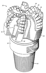
[0013] Figure 2 shows an oblique view of one embodiment of a drill bit which
can be made according to the invention.
[0014] Figure 3 shows an end view of the example bit in Figure 2.
[0015] Figure 4 shows one embodiment of a rupture disk which can be used in a
bit according to the invention.
[0016] Figure 5 shows an example of a pressure relief valve which can be used
in
a bit according to the invention.
[0017] Figure 6 shows another type of pressure relief valve which can be used
in
a bit according to the invention.
[0018] Figure 7 shows another embodiment of a flow relief according to the
invention.
Detailed Description
[0019] Figure 1 shows a drill bit 10 which may be any one of a number of
various
embodiments of the invention as it is used to drill a wellbore 5 through earth
formations 8. The drill bit 10 is coupled to the lower end of a drill string
4,
which typically includes segments of drill pipe (not shown separately)
threadedly
coupled together. The drill bit 10 may be coupled to the drill string 4
directly or
3a
CA 02392937 2002-07-10
through various drilling tools such as a drill collar 6, and rotary steerable
drilling
system 7. It should be understood that the drill string configuration shown in
Figure 1 is only one example of a drilling tool assembly which may be used
with
a drill bit according to the invention, and therefore, the drill string
configuration
of Figure 1 is not intended to limit the invention. The drill string 4 may be
rotated by a rotary table (not shown in Figure 1) or a top drive system 2
which is
itself hoisted and lowered by a drilling rig 1. Drilling fluid ("drilling
mud") is
circulated through the drill string 4 by mud pumps 3 of any type known in the
art. The drilling mud is pumped through the interior of the drill string 4
where it
is ultimately discharged through jets (not shown in Figure 1) on the drill bit
10.
After being discharged through the jets, the drilling mud returns to the
earth's
surface through an annular space between the wellbore 5 and the exterior of
the
drill string 4. As is known in the art, the number of, placement of and sizes
of
the jest (not shown in Figure 1) are selected to provide a desired amount of
fluid
pressure drop in the drill string, among other factors.
[0017] A typical drill bit which may include any one or more of a number of
various embodiments of the invention is shown in oblique view in Figure 2. The
drill bit 10 includes a bit body 12 made from steel or matrix material. The
bit
body 12 typically has a coupling 14, usually a threaded pin or box, to attach
it to
the drill string (4 in Figure 1). This particular bit bodyl2 includes a
plurality of
blades 16 onto which are affixed cutting elements 18, such as polycrystalline
diamond compact ("PDC") inserts, for example. Referring to Figure 3, the drill
bit 10 includes jets 20 which, as previously explained, provide a path for
discharging the drilling fluid from the interior of the drill string (4 in
Figure 1)
into the wellbore (S in Figure 1 ). One or more of the ports (not shown
separately
in Figure 3) for the jets 20 may alternatively be filed with a solid plug
instead of
a jet. This example drill bit 10 also includes one or more adjustable ports
22,
some of which may include a solid plug therein, or a fixed orifice, depending
on
4
CA 02392937 2002-07-10
the total flow area (TFA) required for the particular drill bit and earth
formations
being drilled. As is known in the art, the flow area of each of the jets 20
and any
orifices in the adjustable ports 22 are selected to provide the desired amount
of
TFA for the drill bit 10. In prior art drill bits, as explained in the
Background
section herein, changing the TFA includes changing any one of more of the jets
20 and/or plugs or orifices in any of the adjustable ports 22.
[0018] Although a bit according to the invention is shown in Figures 2 and 3
as
being included in a PDC (fZxed cutter) drill bit, it should be clearly
understood
that the invention is equally applicable to roller cone bits. Accordingly the
type
of bit is not intended to Iimit the scope of the invention. Irrespective of
the type
of bit, for purposes of defining the invention, the bit body can be thought of
as
having at least one cutting element operatively coupled to the bit body. In
the
case of PDC or similar fined cutter bits, such as shown in Figures 2 and 3,
the
cutting element is affixed to the bit body. Roller cone bits have at least one
cutting element in the form of a milled tooth or insert affixed to at least
one roller
cone, which is itself rotatably mounted to the bit body.
[0019] Generally speaking, a drill bit according to the invention includes at
least
one flow relief disposed in the bit to make an hydraulic connection between
the
interior of the bit body and the exterior of the bit body upon application of
a
selected drilling fluid flow characteristic to the interior of the drill bit.
The
selected fluid flow characteristic may include application of a selected
differential pressure, or application of a selected fluid flow rate and/or
total mud
flow volume to the drill bit. The at least one flow relief is adapted to
provide an
increase in TFA when the at least one flow relief is actuated.
[0020] One embodiment of a flow relief can be better understood by referring
to
Figure 4. In Figure 4, the flow relief is a rupture disk 24. The rupture disk
24
may be adapted to fit in any one or more of the adjustable ports (22 in Figure
3)
or may be adapted to replace any one or more of the jets (20 in Figure 3).
s
CA 02392937 2002-07-10
Rupture disks such as may be used in some embodiments of the invention are a
type of plug which is adapted to fail (open to flow permanently) at a selected
differential pressure. One type of rupture disk is described, for example, in
a
brochure entitled, Pressure Activation Device, published by Fike Corporation,
Blue Springs, MO 64105 ( 1999). In a drill bit according to this embodiment of
the invention, the TFA of the bit (10 in Figure 3) may increased by
momentarily
increasing the flow rate from the mud pumps (3 in Figure 1) to provide a
pressure drop across the bit which exceeds the rated burst or failure pressure
of
the rupture disk 24. When ruptured, the disk 24 provides an additional flow
area
through the bit, thereby increasing the TFA. The rated failure pressure of the
rupture disk 24 can be selected to provide the increased TFA where, for
example,
a rotary steerable drilling system having a limitation on pressure drop is
used, or
where drilling progresses to a depth where it would be useful to increase the
TFA
of the bit to compensate for increases is fluid friction due to the length of
the drill
string (4 in Figure 1).
[0021] In various embodiments of a drill bit according to the invention, any
one
or more of the adjustable ports (22 in Figure 3) or any one or more of the
jets (20
in Figure 3) may be replaced with a rupture disk such as shown at 24 in Figure
4.
[0022] Another embodiment of a flow relief is shown in Figure 5. This
embodiment of flow relief is a biased pressure relief valve 26. Bias may be
provided, for example, by a spring 30 which forces a valve ball 32 against a
valve seat 28 to stop flow until the force of the spring 30 is overcome by
fluid
pressure acting against the ball 32. The pressure relief valve 26 of Figure 5
has
the advantage, as compared to the rupture disk such as shown at 24 in Figure
4,
of being able to close again once the differential pressure across the
pressure
relief valve 26 drops below the rated differential pressure for the valve 26.
As in
the previous embodiment of Figure 4, the pressure relief valve 26 of Figure 5
may be used in any one or more of the adjustable ports 22 or any one or more
of
6
CA 02392937 2002-07-10
the jet ports on the bit body ( 12 in Figure 2). When opened, the pressure
relief
valve 26 provides increased TFA to the bit.
[0023] Another embodiment of a flow relief which can be used with a bit
according to the invention is shown in Figure 6. The flow relief 34 shown in
Figure 6 is a type of relief valve which may be similar in principle to "gas
lift"
valves used in some oil production systems. This type of relief valve is
adapted
to be opened upon application of a selected range of differential pressure,
and is
adapted to be closed at all other values of differential pressure. This
adaptation
is enabled by having a port 42 in a biased valve body 36 that is aligned with
a
corresponding port 44 in the valve housing 40 upon movement of the valve body
36 a selected distance. The selected distance is related to the biasing force
from,
for example, a spring 38, and the cross sectional area of the valve body 36.
As in
the previous embodiment, the flow relief 34 of Figure 6 may be used in any one
or more of the adjustable ports 22 or jet ports on the bit body (12 in Figure
2).
When opened, the pressure relief valve 34 provide increased TFA to the bit.
[0024] Still another type of flow relief shown in Figure 7 is adapted to
provide an
increase in TFA only by the flow of drilling mud through the bit for a
selected
time, and/or total flow volume. The flow relief 20A in Figure 7 can be similar
in
construction to a conventional jet or nozzle, but includes an erodible
material 54
disposed on an interior surface of the orifice of the jet body 52. The jet
body 52
may be made from conventional jet body materials, such as tungsten carbide,
while the erodible material 54 may be mild steel, or other substance that is
adapted to wear away by the flow of mud through the relief 20A. When the
erodible material 54 is worn away, the relief 20A presents a larger flow area
to
the bit than when the erodible material 54 is intact. A flow relief such as
shown
in Figure 7 may be configured to provide the larger flow area of the jet body
52
after a selected volume of drilling mud has passed through the erodible
material
54. The total flow volume , as is known in the art, is related to the rate at
which
CA 02392937 2002-07-10
the mud pumps (3 in Figure 1) discharge drilling mud, and the uneroded orifice
flow area of the flow relief ZOA. As is the case for the other embodiments of
flow relief according to the invention, the flow relief 20A of Figure 7 may be
inserted into any one or more of the adjustable ports (22 in Figure 3) or may
substitute any one or more of the jets (20 in Figure 3).
[0025] Various embodiments of the invention provide a drill bit which can have
the total flow area changed during drilling without the need to remove the
drill
bit from the wellbore.
[0026] While the invention has been described with respect to a limited number
of embodiments, those skilled in the art will appreciate that other
embodiments
of the invention can be readily devised which do not depart from the spirit of
the
invention as disclosed herein. Accordingly, the invention shall be limited in
scope only by the attached claims.
s