Note: Descriptions are shown in the official language in which they were submitted.
CA 02392974 2002-07-09
O1P12240
Dielectric barrier discharge lamp having a starting aid
TECHNICAL FIELD
The invention relates to a dielectric barrier discharge
lamp and a lighting system having such a lamp and an
electric power supply unit.
The term "dielectric barrier discharge lamp" in this
case covers sources of electromagnetic radiation based
on dielectrically impeded gas discharges. The spectrum
of the radiation emitted by the gas discharge can in
this case comprise both the visible region and the UV
(ultraviolet)/VUV (vacuum ultraviolet) region and the
IR (infrared) region. Furthermore, it is also possible
to provide a fluorescent layer for converting invisible
radiation into visible radiation (light).
The discharge vessel is usually filled with a rare gas,
for example xenon, or a gas mixture. What are termed
excimers are formed during the gas discharge, which is
preferably operated by the use of a pulsed operating
method described in US-A 5,604,410. Excimers are
excited molecules, for example Xe2*, which emit
electromagnetic radiation upon return to the generally
unbonded ground state. In the case of Xe2*, the maximum
of the molecular band radiation is approximately 172
nm.
A dielectric barrier discharge lamp necessarily has at
least one so-called dielectrically impeded electrode. A
dielectrically impeded electrode is separated from the
interior of the discharge vessel by the use of a
dielectric barrier. By way of example, this dielectric
barrier may be designed as a dielectric layer which
covers the electrode, or formed by the discharge vessel
of the lamp itself, specifically if the electrode is
CA 02392974 2002-07-09
- 2 -
arranged on the outer wall of the discharge vessel.
Because of the dielectric barrier, the operation of
such lamps requires a time-variable voltage between the
electrodes, for example a sinusoidal AC voltage or
pulsed voltage as disclosed in US-A 5,604,410.
In the case of dielectric barrier discharge lamps, the
first ignition or ignition after lengthy operating
pauses is frequently difficult, in particular after
lengthy storage of the lamps in the dark. As a rule, a
substantially higher voltage is required than in normal
operation. Moreover, upon first ignition a filamentary
partial discharge frequently occurs which is undesired,
since its useful radiation emission is inefficient by
comparison with that of the discharge form disclosed in
US-A 5,604,410.
BACKGROUND ART
Patent US-A 6,097,155 has already disclosed a
dielectric barrier discharge lamp having an elongated
discharge vessel and having elongated dielectrically
impeded electrodes arranged on the inside of the
discharge vessel wall along the longitudinal axis.
A high-power radiator based on dielectrically impeded
discharge is disclosed in US-A 5,432,398 in the form of
a coaxial double-tube arrangement. An outer electrode
in the form of a wire mesh extends over the entire
circumference of the outer quartz tube. A helical inner
electrode is pushed into the inner quartz tube. The
interior of the inner quartz tube is filled with a
cooling liquid that has a high dielectric constant and,
in addition to serving the purpose of cooling, also
serves to couple the inner electrode to the inner
quartz tube. A multiplicity of discharge channels form
between the electrodes upon the application of an AC
voltage in the space between the two tubes, the
CA 02392974 2002-07-09
- 3 -
discharge space. For the purpose of improving the
ignition behavior during the first ignition or after
lengthy operational pauses, means are provided that
force an initial ignition by means of local field
distortion or field prominence at a point in the
discharge space. The reliable ignition of the entire
discharge volume is then forced by the UV radiation
produced in this case and the charge carriers of this
local discharge. The following are disclosed as
suitable means for the field distortion: a dent in the
inner or outer tube that reaches approximately up to
half the gap width to the respective other tube; a
sphere of dielectric material in the discharge space; a
quartz droplet fused onto the inner surface of the
outer tube or the outer surface of the inner tube.
DISCLOSURE OF THE INVENTION
It is the object of the present invention to provide a
dielectrically impeded barrier discharge lamp which
demonstrates improved ignition behavior.
This object is achieved by means of a dielectric
barrier discharge lamp having an elongated discharge
vessel defining a longitudinal axis, and having
elongated dielectrically impeded electrodes arranged on
the discharge vessel wall along this longitudinal axis,
and having at least one electrically conductive means
that extends with reference to the longitudinal axis
only over a subregion of the discharge vessel wall and
that is arranged on the discharge vessel wall to
support the ignition of the dielectrically impeded
discharge.
Also claimed is a lighting system having the above-
named dielectric barrier discharge lamp and having a
voltage source with two poles which can provide a
pulsed-voltage sequence at these two poles, electrodes
being connected to the two poles.
CA 02392974 2002-07-09
- 4 -
The dielectric barrier discharge lamp according to the
invention has at least one electrically conductive
means for supporting the ignition of the dielectrically
impeded discharge that is arranged on the discharge
vessel wall and extends with reference to the
longitudinal axis only over a subregion of the
discharge vessel wall.
It is assumed according to the present state of
knowledge - without hereby intending to fix the
theoretical interpretation - that this means permits an
initial ignition between this means and at least one
dielectrically impeded electrode more specifically at
voltages that are already lower than without this
means. This initial ignition then effects an ignition
of the actual discharge between the dielectric
electrodes. In addition, the means greatly reduces the
probability of the undesired occurrence, mentioned at
the beginning, of the filamentary partial discharge.
In a preferred embodiment, the dielectric barrier
discharge lamp has inner electrodes, since this
embodiment in accordance with US-A 6,097,155 has proved
to be particularly efficient. In this case, the
dielectrically impeded electrodes are implemented by
means of elongated electrodes that are arranged on the
inside of the wall of the discharge vessel and are
covered by a dielectric layer. The electrically
conductive means is arranged on the outside of the wall
of the discharge vessel.
This embodiment has the additional advantage that the
means can be applied from the outside, that is to say
after fabrication of the discharge vessel. Suitable in
this case as electrically conductive means is, inter
alia, a ring or part of a ring, in particular made from
metal, which can also be mounted subsequently on the
elongated discharge vessel, particularly in the form of
CA 02392974 2002-07-09
- 5 -
a circular tube. Moreover, it is also possible to
conceive further refinement of the means which fulfill
the above-named purpose, for example a filament or
spring tightly wound around the discharge vessel.
Finally, a differently shaped planar refinement of the
means is also possible in principle, for example a
metal sheet of rectangular, round or oval shape,
although further arrangements for fastening the means
on the wall of the discharge vessel are to be taken in
some circumstances. This can be avoided when the means
is implemented by a corresponding conductive coating,
for example a metal solder layer.
The width of the means along the longitudinal axis of
the discharge vessel is typically between approximately
1 mm and a few 10 mm, particularly between 3 mm and
15 mm. It has proved that this is sufficient as a rule
for reliable ignition, on the one hand, and that the
light emitted by the lamp is still shaded to a
relatively small extent, on the other hand. Moreover,
the means is preferably arranged at one end of the
discharge vessel. It has proved to be advantageous in
this case when the means overlaps one end of the
elongated electrodes. An overlap of a few mm, in
particular approximately 1 mm, is already sufficient.
However, the means can also overlap the elongated
electrodes over its entire width.
In the case of very long lamps, it can possibly also be
advantageous to provide two means, for example one at
each end of the lamp, or else several means distributed
along the lamp axis, in order to ensure rapid and
uniform ignition of the entire lamp.
In a further preferred embodiment, the lamp has a base
at at least one end, the means being integrated in the
base.
Although the electrically conductive means can also be
CA 02392974 2002-07-09
- 6 -
at a floating electric potential, it has proved to be
favorable when the means is connected to ground
potential, preferably to the plane potential of the
voltage source supplying the lamp. The connection to
plane potential has the advantage that defined voltage
conditions are set up between the means and electrodes.
In order to make up a complete lighting system, the
electrodes of the dielectric barrier discharge lamp
according to the invention are connected to the
associated poles of a voltage source. The means is
connected to constant potential, with reference to the
time-variable voltage at the poles of the voltage
source. The voltage source is preferably designed in
such a way that it can provide a pulsed-voltage
sequence at its poles. Reference is made to US
6,323,600 for further details on this. It is
particularly preferred to design the voltage source in
such a way that the voltage source can provide a
symmetrical pulsed-voltage sequence with reference to
its plane potential, the means being connected to the
plane potential. The use of a symmetrical voltage has
the advantage here, inter alia, that no undesired
capacitive currents flow via the means to the ground
line.
BRIEF DISCRIPTION OF THE DRAWINGS
The aim below is to explain the invention in more
detail with the aid of exemplary embodiments. In the
drawing,
Figure 1 shows a schematic plan view of a first
exemplary embodiment,
Figure 2 shows a schematic plan view of a second
exemplary embodiment.
BEST MODE FOR CARRYING OUT THE INVENTION
CA 02392974 2002-07-09
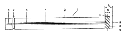
Figure 1 shows a tubular fluorescent lamp 1. The lamp 1
essentially comprises a tubular discharge vessel 2 made
from soda-lime glass with a circular cross section, as
well as two strip-shaped electrodes 3 (the second
electrode is covered and therefore cannot be seen),
which are applied, arranged parallel to the tube
longitudinal axis and diametrically relative to one
another, to the inside of the wall of the discharge
vessel 2. Each of the inner electrodes 3 is covered by
a dielectric barrier 4 made from glass solder.
Furthermore, the inside of the wall of the discharge
vessel is covered by a fluorescent layer (not shown for
reasons of presentation).
A first end of the discharge vessel 2 is sealed by
means of butt fusion 5. The two electrodes 3 end at a
short distance A=8 mm in front of this fusion 5. The
electrodes 3 are guided to the outside in a gastight
fashion through the other end of the discharge vessel
2, and merge there in each case into an external supply
lead 6. The second end of the discharge vessel 2 is
sealed by means of a plate-shaped sealing element (not
detectable in this illustration). To this end, the edge
of the plate-shaped sealing element is fused with a
restriction 7 of the discharge vessel 2. For further
details on this, reference is made to WO 02/27747.
Arranged at the first end of the discharge vessel 2 is
a metal ring 8 of width B=5mm - viewed in the direction
of the longitudinal axis of the discharge vessel 2 - on
the outside of the wall of the discharge vessel 2.
Moreover, the metal ring 8 is positioned such that it
covers the end, facing the first end of the discharge
vessel 2, of the electrodes 3 by the overlap D=1 mm.
The metal ring 8 is illustrated transparently in figure
1 for the purpose of better understanding of the
conditions.
CA 02392974 2002-07-09
The lamp 1 is provided for a pulsed mode of operation
in accordance with the already mentioned US-A
5,604,410. For this reason, the two outer supply leads
6 of the dielectric barrier discharge lamp 1 are
connected to the two poles of a voltage source (not
illustrated). The voltage source is designed to provide
at its two poles a pulsed-voltage sequence that is
symmetrical with reference to a plane potential.
Reference is made with regard to such a voltage source
to US 6,172,467. The metal ring 8 is connected via a
connection 9 to the plane potential of the voltage
source . Consequently, the metal ring 8 acts as a means
for improving the ignition behavior, as a result of
which markedly lower voltages are required for igniting
the lamp after long operational pauses than without the
ring.
A variant of the lamp from figure 1 is illustrated in
figure 2. Here, the same features are provided with the
same reference numerals. The variant in figure 1
differs in that the metal ring 8 is pushed over the
second end of the discharge vessel 2, and is arranged
over the constriction 7 (covered here and therefore not
visible). The advantage of this variant consists in
that the connection 9 can be guided to the voltage
source at the second end of the lamp in common with the
feed lines (not illustrated) for the supply leads 6 of
the electrodes 3. Moreover, it has been proved that in
this variant the probability of the undesired
occurrence, mentioned in the beginning, of the
filamentary partial discharge is reduced in a
particularly marked fashion. A connection to a defined
electric potential (plane or ground potential) is not
mandatory in this case. It is probable in each case
that the metal ring 8 over the constriction has a
favorable influence on the electric field in the region
of the lead-through of the supply leads 6 into the
interior of the discharge vessel 2.
CA 02392974 2002-07-09
_ g _
In a development, the lamp is provided with a base (not
illustrated) in which the metal ring is integrated.