Language selection

Search

Patent 2393099 Summary

Third-party information liability

Some of the information on this Web page has been provided by external sources. The Government of Canada is not responsible for the accuracy, reliability or currency of the information supplied by external sources. Users wishing to rely upon this information should consult directly with the source of the information. Content provided by external sources is not subject to official languages, privacy and accessibility requirements.

Claims and Abstract availability

Any discrepancies in the text and image of the Claims and Abstract are due to differing posting times. Text of the Claims and Abstract are posted:

  • At the time the application is open to public inspection;
  • At the time of issue of the patent (grant).
(12) Patent Application: (11) CA 2393099
(54) English Title: GAS HEATING APPLIANCE
(54) French Title: CUISINIERE A GAZ
Status: Deemed Abandoned and Beyond the Period of Reinstatement - Pending Response to Notice of Disregarded Communication
Bibliographic Data
(51) International Patent Classification (IPC):
  • F24C 3/02 (2006.01)
  • F23D 14/06 (2006.01)
  • F23D 14/46 (2006.01)
  • F24C 3/08 (2006.01)
  • F24C 15/10 (2006.01)
  • F24C 15/12 (2006.01)
(72) Inventors :
  • BROWN, SIMON DENZIL (New Zealand)
(73) Owners :
  • FISHER & PAYKEL APPLIANCES LIMITED
(71) Applicants :
  • FISHER & PAYKEL APPLIANCES LIMITED (New Zealand)
(74) Agent: RICHES, MCKENZIE & HERBERT LLP
(74) Associate agent:
(45) Issued:
(86) PCT Filing Date: 2000-12-22
(87) Open to Public Inspection: 2001-07-12
Examination requested: 2003-12-22
Availability of licence: N/A
Dedicated to the Public: N/A
(25) Language of filing: English

Patent Cooperation Treaty (PCT): Yes
(86) PCT Filing Number: PCT/NZ2000/000263
(87) International Publication Number: NZ2000000263
(85) National Entry: 2002-05-30

(30) Application Priority Data:
Application No. Country/Territory Date
502170 (New Zealand) 2000-01-06

Abstracts

English Abstract


The present invention relates to a gas burner particularly suited for gas
heating applicances for cooking food. In particular the present invention
comprises a generally circular moulded body (100) including gases inlet (106)
and an internal cavity (114). The internal cavity (114) is covered by a
substantially transparent glass cap (108), which also bounds on the gas
outlets (116). In this fashion, due to the transparency of the glass cap (108)
at low flame improve controllability and safety are achieved by visual
feedback of the flame size.


French Abstract

La présente invention concerne un brûleur à gaz particulièrement adapté pour les cuisinières à gaz servant à la cuisson d'aliments. La présente invention concerne, en particulier, un corps moulé (100) généralement circulaire comprenant une entrée (106) de gaz et une cavité interne (114). La cavité interne (114) est recouverte d'un couvercle de verre (108) sensiblement transparent, se fixant également aux sorties (116) de gaz. La transparence du couvercle de verre (108) à faible flamme, permettant de voir la dimension de la flamme, augmente ainsi la capacité de réglage et la sécurité.

Claims

Note: Claims are shown in the official language in which they were submitted.

-5-
CLAIMS
1. A gas burner comprising:
a body portion including a gas inlet and an open inner cavity in fluid
communication with said gas inlet,
a substantially transparent cover means adapted to engage or attach to said
body
portion and thereby substantially cover said inner cavity and,
a plurality of gas outlets substantially adjacent the boundary formed between
said
cover means and said body portion and in fluid communication with said inner
cavity,
wherein at least a portion of said gas outlets being visible through said
cover
means.
2. A gas burner as claimed in claim 1 wherein said cover means is
substantially
composed of glass.
3. A gas burner as claimed in claim 1 wherein said cover means is composed of
a
glass mixture with substantial resistance to thermal shock.
4. A gas burner as claimed in claim 1 wherein said cover means is composed of
glass
ceramic.
5. A gas burner as claimed in claim 1 wherein said cover means is composed of
a
silica based glass mixture.
6. A gas burner as claimed in claim 1 wherein said cover means in composed of
a
borosilicate glass mixture.
7. A gas burner as claimed in any one of the preceeding claims wherein said
plurality
of gas outlets comprises a number of channels formed in what is in use the
upper face of
said body portion, said channels running from the inner cavity of said body
portion to the

-6-
outer circumference of said body portion.
8. A gas burner as claimed in any one of claims 1 to 6 wherein said plurality
of gas
outlets comprises a number of channels formed in what is in use the lower face
of said
cover means, said channels running from (when said cover means is in place
atop said
body portion) the inner cavity of said body portion to the outer circumference
of said
body portion.
9. A gas burner as claimed in any one of claims 1 to 6 wherein said plurality
of gas
outlets comprise a plurality of holes in said body portion, extending .from
said inner cavity
to the exterior.
10. A gas burner as claimed in any one of the proceeding claims wherein said
cover
means includes lettering or designs moulded into or printed onto what is in
use the
underside of said cover means.
11. A gas burner as claimed in any one of the proceeding claims wherein said
body
portion includes a centre portion and said inner cavity comprising an annular
cavity
around said centre portion, said plurality of gas outlets comprising inner
outlets facing
inwardly substantially toward the centre of said burner and outer outlets
facing
substantially outwardly of said burner, and said cover means comprising a
substantially
transparent annular ring substantially covering said annular cavity.
12. A gas burner as claimed in any one of the proceeding claims wherein said
cover
means including a tapered portion on the outer circumference thereof.
13. A gas burner substantially as herein described with reference to and as
illustrated
by the accompanying figures.

Description

Note: Descriptions are shown in the official language in which they were submitted.


CA 02393099 2002-05-30
WO 01/50065 PCT/NZ00/00263
-1-
GA,.S HEATING APPLIANCE
TECHNICAL FIELD
This invention relates to a substantially transparent cap for a heating
appliance
particularly though not solely for use as a gas burner cooktop.
BACKGROUND ART
There are a number of methods known in the art for providing heating in a cook
top. One of the preferred methods is using a gas burner due to the ability to
deliver high
levels of heating when required and also relatively fine levels of control. It
is typical of
such gas burners that the finest levels of control will be desired at the low
end of the
output range.
Various methods have been postulated in order to implement fine control in the
lower output range. For example, US 5,009,393 discloses a gas turn down valve
with a
relatively gradual control characteristic which provides a greater level of
control
especially at lower outputs compared to traditional gas valves. In a further
improvement
described in Korean Patent 9,208,198 an electromechanical actuator is used to
rotate the
gas valve in order to achieve fine levels of control across the entire range
of output.
However, while these prior art systems do provide improved control, it would
be
desirable to have a simple system which by way of visual feedback allowed fine
control
at low levels of burner output.
DISCLOSURE OF THE INVENTION
It is an object of the present invention to provide a gas burner which goes
someway
to achieving the above mentioned desiderata or which will at least give the
public a useful
choice.
Accordingly in a first aspect the present invention consists in gas burner
comprising:
a body portion including a gas inlet and an open inner cavity in fluid
communication with said gas inlet,
a substantially transparent cover means adapted to engage or attach to said
body
portion and thereby substantially cover said inner cavity and,
a plurality of gas outlets substantially adjacent the boundary formed between
said

CA 02393099 2002-05-30
WO 01/50065 PCT/NZ00/00263
-2-
cover means and said body portion and in fluid communication with said inner
cavity.
To those skilled in the art to which the invention relates, many changes in
construction and widely differing embodiments and applications of the
invention will
suggest themselves without departing from the scope of the invention as
defined in the
appended claims. The disclosures and the descriptions herein are purely
illustrative and
are not intended to be in any sense limiting.
BRIEF DESCRIPTION OF THE DRAWINGS
One preferred form of the present invention will now be described with
reference
to the accompanying drawings in which;
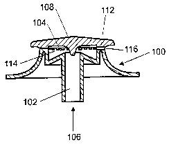
Figure 1 is a cut-away view of the gas burner according to the preferred
embodiment of the present invention,
Figure 2 is a plan view of the body portion according to the preferred
embodiment
of the present invention,
Figure 3 is a perspective view of the substantially transparent glass burner
cap
according to the preferred embodiment of the present invention,
Figure 4 is a plan view of the gas burner at a low flame setting according to
the
preferred embodiment of the present invention,
Figure 5 is a plan view of the gas burner on a high flame setting according to
the
preferred embodiment of the present invention,
Figure 6 is a side view of the wok-style burner, and
Figure 7 is a plan view of the wok-style burner.
BEST MODE FOR CARRYING OUT THE INVENTION
Referring now to Figure 1 and 2 a gas burner is shown according to the
referred
embodiment of the present invention. The gas burner is formed of a body
portion 100
including a gas inlet 102 and an internal cavity 104 such that the gas flows
from the gas
supply 106 into the internal cavity 104. The top of the internal cavity 104 is
closed off
with a substantially transparent glass cap 108 which attaches overtop of and
overhangs the
body portion 100. The gas then flows from the internal cavity out through
outlet channels
112 formed on the top face 114 of the body portion 100 to the outlet ports 116
where the
gas is ignited and heats the cooking vessel (not shown).

CA 02393099 2002-05-30
WO 01/50065 PCT/NZ00/00263
-3-
Referring to Figure 3 ~ a see the burner cap 108 in more detail. The cap 108
may
optionally include a central co a 1 SO designed to fit down the internal
cavity (104, Figure
1 ) of the body portion ( 100, Figure 1). On the underside is a flat annular
face 152
designed to sit firmly upon the upper face ( 114, Figure 1 ) of the body
portion. The cap 108
also includes an outer flange 156, which overhangs the body portion ( 100,
Figure 1 ). The
outer flange 156 is designed to diffuse the flames before they contact the
heating vessel.
The glass cap itself is composed of a typical ceramic type glass. Such glass
is
designed with a significant resistance to thermal shock and high contact
temperature, such
as expected when exposed to a gas fuelled flame. A Borosilicate based glass
would be
particularly appropriate.
The present invention is shown in use in Figures 4 to 5. At low flame, seen in
Figure 4 the actual flame 200 is only seen by virtue of the cap 202 being
transparent. At
high flame the flames 204 extent past the outer flange 206, and are evenly
distributed
around the circumference. By virtue of the flames being visible at low flame
more
accurate control and greater safety is possible over prior art burners.
A further improvement would be to mould designs or text onto the underside of
the
glass cap. This would allow the top face to be easily cleaned. The
manufacturers name
or other designs would then be visible from above.
It will be appreciated that by providing a low thermally conductive material
such
as the glass cap as opposed to the conventional cast iron, or highly thermally
conductive
caps, that the performance of the gas burner may improve. At low flame with a
highly
thermally conductive cap there is the potential for ''quelching" or partial
extinction of the
flame. This results in partial combustion with the by-product of higher CO
emissions.
With the low thermal conductivity of the glass cap according to the present
invention, the
potential for "quelching" is much reduced. Therefore the burning is more
controlled, more
efficient and the CO emissions are potentially reduced, especially at low
outputs.
Another advantage to the present invention relates to the fact that with glass
or
other transparent thermally retardant material as the burner cap, the need for
a separate
coating operation of the burner cap is eliminated. Traditionally with cast
iron or cast
aluminium burner caps, due to the fact that they are constantly in contact
with combusting

CA 02393099 2002-05-30
WO 01/50065 PCT/NZ00/00263
-4-
illustrated in a configuration for a wok-style burner. In this case the main
body 210 is
substantially composed as described in the preceeding embodiments, having
outlets 212
on the outer periphery 214 of a raised portion 211 inset from the edge of the
main body
210. However rather than having the inner cavity completely open, the main
body
includes a covered centre section 216 extending approximately 2/3 the radius
of the outer
periphery 214 to form an inner periphery 218 to the raised portion. Included
on the inner
periphery are a further set of outlet ports 220 to provide flames towards the
centre of the
wok to provide more even heating and to ensure that the centre of the wok is
sufficiently
hot as is often desirable when cooking with a wok.
Also shown in Figures 6 and 7 is the trivet plate 222 which supports the wok
(not
shown) above the flames. The trivet 222 supports the wok about an annular path
224
which allow the wok (not shown) to be readily moved and removed, ensuring
adequate
flame contact to the underside of the wok and minimal flame contact on the
trivet.
The substantially transparent glass cap 226 as described in the previous
embodiments is in this case embodied in an annular ring with tapered portions
(or rounded
edges) at its inner 228 and outer 230 peripheries. Again the cap 226 is
composed of a
similar material and at low flame ensures full visibility of the flame. At
high flame as
shown in Figure 6, the flames can be seen both inwardly and outwardly of the
raised
portion 211. It will be readily apparent to one skilled in the art the
advantages to the
system described above and as defined in the appended claims.

Representative Drawing
A single figure which represents the drawing illustrating the invention.
Administrative Status

2024-08-01:As part of the Next Generation Patents (NGP) transition, the Canadian Patents Database (CPD) now contains a more detailed Event History, which replicates the Event Log of our new back-office solution.

Please note that "Inactive:" events refers to events no longer in use in our new back-office solution.

For a clearer understanding of the status of the application/patent presented on this page, the site Disclaimer , as well as the definitions for Patent , Event History , Maintenance Fee  and Payment History  should be consulted.

Event History

Description Date
Application Not Reinstated by Deadline 2006-12-22
Time Limit for Reversal Expired 2006-12-22
Inactive: IPC from MCD 2006-03-12
Deemed Abandoned - Failure to Respond to Maintenance Fee Notice 2005-12-22
Letter Sent 2004-01-23
Request for Examination Received 2003-12-22
Request for Examination Requirements Determined Compliant 2003-12-22
All Requirements for Examination Determined Compliant 2003-12-22
Inactive: Office letter 2003-10-07
Letter Sent 2003-10-07
Inactive: Single transfer 2003-07-15
Amendment Received - Voluntary Amendment 2003-04-22
Inactive: Courtesy letter - Evidence 2002-11-05
Inactive: Cover page published 2002-11-01
Inactive: Notice - National entry - No RFE 2002-10-30
Application Received - PCT 2002-08-26
National Entry Requirements Determined Compliant 2002-05-30
Application Published (Open to Public Inspection) 2001-07-12

Abandonment History

Abandonment Date Reason Reinstatement Date
2005-12-22

Maintenance Fee

The last payment was received on 2004-11-09

Note : If the full payment has not been received on or before the date indicated, a further fee may be required which may be one of the following

  • the reinstatement fee;
  • the late payment fee; or
  • additional fee to reverse deemed expiry.

Patent fees are adjusted on the 1st of January every year. The amounts above are the current amounts if received by December 31 of the current year.
Please refer to the CIPO Patent Fees web page to see all current fee amounts.

Fee History

Fee Type Anniversary Year Due Date Paid Date
MF (application, 2nd anniv.) - standard 02 2002-12-23 2002-05-30
Basic national fee - standard 2002-05-30
Registration of a document 2002-05-30
MF (application, 3rd anniv.) - standard 03 2003-12-22 2003-11-12
Request for examination - standard 2003-12-22
MF (application, 4th anniv.) - standard 04 2004-12-22 2004-11-09
Owners on Record

Note: Records showing the ownership history in alphabetical order.

Current Owners on Record
FISHER & PAYKEL APPLIANCES LIMITED
Past Owners on Record
SIMON DENZIL BROWN
Past Owners that do not appear in the "Owners on Record" listing will appear in other documentation within the application.
Documents

To view selected files, please enter reCAPTCHA code :


To view images, click a link in the Document Description column (Temporarily unavailable). To download the documents, select one or more checkboxes in the first column and then click the "Download Selected in PDF format (Zip Archive)" or the "Download Selected as Single PDF" button.

List of published and non-published patent-specific documents on the CPD .

If you have any difficulty accessing content, you can call the Client Service Centre at 1-866-997-1936 or send them an e-mail at CIPO Client Service Centre.

({010=All Documents, 020=As Filed, 030=As Open to Public Inspection, 040=At Issuance, 050=Examination, 060=Incoming Correspondence, 070=Miscellaneous, 080=Outgoing Correspondence, 090=Payment})


Document
Description 
Date
(yyyy-mm-dd) 
Number of pages   Size of Image (KB) 
Representative drawing 2002-05-29 1 5
Description 2002-05-29 4 203
Abstract 2002-05-29 1 55
Claims 2002-05-29 2 84
Drawings 2002-05-29 4 56
Description 2002-05-29 4 196
Notice of National Entry 2002-10-29 1 192
Request for evidence or missing transfer 2003-06-01 1 102
Courtesy - Certificate of registration (related document(s)) 2003-10-06 1 106
Acknowledgement of Request for Examination 2004-01-22 1 174
Courtesy - Abandonment Letter (Maintenance Fee) 2006-02-15 1 174
PCT 2002-05-29 11 439
Correspondence 2002-10-29 1 24
Correspondence 2003-10-06 1 12
Fees 2003-11-11 1 36
Fees 2004-11-08 1 32