Note: Descriptions are shown in the official language in which they were submitted.
CA 02393203 2002-05-31
A 50001
spaniol. ~lrmin
METHOD AND ,~R.R~NG.EMENT FOR S1M'ULAT1NG1.~N A$RUPT SPREADING OF
FLAMES
The invcntiort .relates to a method and an arrangerrtent for simulating an
abzupt spreading of
flames in a firefighter tzainiz~g installation having a burn zoom for at least
one further .fire
place, wherein a 5as is directed near to the ceiling of the burn room and is
ignited.
~, spontanEOUS spreading of flames, starting from the ceiling of a zoom that
encloses a
fireplace, and more oz less $pzeadina across the vvhole ceiling like a sea of
flames and
penetrating into the .room. respectively, is refEZTed to as "flashover" in the
art and involves
high potential dangers for firefighters upon extinguishing a fire. Due to
widespread use of
synthetic materials: tlashovers tend to occur more and more often; thus
firefightezs have to be
trained to be prepared to a corresponding dangerous situation.
Flashover characteristics arise in dependence upon a plurality of parameters
such as
temperature, volume of the burn roozrv, amount of oxygen, amount of bwnned
gas, amount of
unburned gas, amount and type of solid combustibles resting unburned, amount
and type of
combustible zrtaterials, ignition tempErature(s) and/or the like as a function
of time. Despite
this laxge number o.f parameters defining a t~lashover, it has been found that
there are always
specific warning signals with a relatively high probability before a flaehover
actually occurs,
such warning signals being absolutely perceptible by firefighters. Thus, a
room often has been
observed to "respire" ,just before ignition of a flashover therein. More
particularly, according
to eyewitness reports, swaths of smoky; axe escaping a room just before a
flashover ignition,
especially between a door and the associated threshold thereof, deforming the
door outwardly,
and then partially are pulled back into the bum room pulling the door itself
into the burn
room. When a door is opened to a room, in which all the conditions for a
flashover ignition
are already met, such as indicated by said "respirinb", and oxygen is entering
said room, a
simultaneous ignition of unused gases and heated corribu~tibles occurs in the
area of the
ceiling. causing a very rapid generation arid propagation of heat, light and
pressure, thus an
abrupt spreading o.f flames: the t7ashover.
CA 02393203 2002-05-31
-2-
hs life endangering flachovers occur more and more often, known firefvghter
training
installations have been comprising in part an arrangement for simulating a
flashover. For
exunple, EP 0 585 392 B1 disclosesa method oftlae above character, wherein,
for simulating
a Ilashover, fuel in the form of pure propane gas not only is suppliod to a
main burner for a
fireplace near the floor of a burn .room which is to simulate a burning sofa
or the like, but also
to an auxiliary burner. For t:nese purposes at least one firefighter
operational parameter is
monitored and a second flame is produced near the ceiling i.n accordance with
attainment of a
predetermined threshold value of said monitored operational parameter, by
controlling the
supply of pure propane gas to the auxiliary burner in the form of a burn tube
independently of
the appropriate supply to the main burner, and igniting it. hJ(owever, this
known simulation of
a tlachover .through such a second flame is not realistic, for two reasons.
First. no indications
for the development of a flashover are perceptible before entering the burn
room. On the other
hand, the second flame is generated by releasing pure gas from a gas manifold
into the burn
room and igniting it using the air available therein, which causes the flames
to spread
relaCively slowly, or "lazy", as the gas searches for combustible air, which
under no
circumstances is capable of representing the dangers of an actual flashover.
In addition to flashover phenomena, so called "ro.llovers" consisting of fire
.fronts rolling.back
and .forth, a.~ well as "backdrafts" caused by re-ignition of heated items.
are known to involve
abruptly spreading flames.
It is the object of the present invention to improve the method and
arrangement of the
described character so as to overeo.me the drawbacks of the prior art,
particularly to produce a
more realistic abmpt flame propagation than in the prior art, for simulating
flashover, rollover
and/or backdrafl phenomena. ,A.t the same time the safety of the f refighters
to be trained is to
be ensured. Ellso, warning indications of an abrupt sprEading of flames that
is about to
develop should be simulated.
'.Che obiect concerning the inventive method is solved by releasing the gas,
after havinm been
mixed with oxygen, .into the bum chamber as a combustible gas-oxygen mixture
and then
igniting it.
CA 02393203 2002-05-31
Provisions may be zxtade for igniting the gas-oxygen znxxtuc~ within the burn
chamber on at
least two spaced Iocat.ions to generate two. preferably contra-directional,
tire fronts.
Further, the invention proposes to supply said oxygen via air, especially
fresh air.
:~Iso, according to the invention said gas may be supplied in the form of
propane gas,
preferably vaporized.
A prefezTed modification accoadiiig to the invrrition is characterized in that
smoke is pushed
out of the burn room and is subsEquently at least parkially sucked back into
it, at temperatures
above a predetermined temperature threshold value as measured within the burn
room with
the access door closed, said temperature threshold value being characteristic
for the
development of an abrupt spreading of .flames, wherein such smoke movement
preferably is
repeated periodically.
Provisions may be made xor pushing smoke out of the burn. .room and tucking it
back therein,
respectively, for approximately up to one minute each.
Further, the invention proposes to have the smoke .movement stopped by opening
the burn
room access door, and to subsequently initiate the delivery and ignition of
the gas-oxygen
mixture, preferably manually.
The object concerning the azrlngement according to the invention is solved by
a gas-oxygen
supply means adjacent the ceiling of the burnroona, from which a gac-oxygen
mixture is
introduced into the burn roam, flowing to~~ardc at least one ignitor.
T.he gac-oxygen supply means may by adapted to comprise in downstream
direction of the gas
andlor oxygen one after another: a blower for aspirating oxygen particularly
contained in
fresh air, a primary heating chamber for heating the oxygen by absorption of
heat of the burn
room, a pressure attenuation chamber. a gas manifold for introducing gas. such
ac propane gas
or the like. into the pressure attenuation chamber. a mixing chamber for
mixing gas,
preferably evaporated, and axygEn to a combustible gas-oxygen mixtuie, andlor
a unit .for
preventing sucking back, such as in x.he form of a cheek flap ox the like.
CA 02393203 2002-05-31
_g_
Further, according to he invention the ignitor is proposed to comprise a pair
of oppositely
extending electrodes having two oppositely: facixag end faces. each providing
an ignition
surface. and a curxent supply line
Additionally, the ignitor may be adapted to have at least one ignition surface
disposed at not
more than one meter in front of the gas-oxygen mixture outlet of said gas-
oxygen supply
means.
Further, a manual control unit may be provided for activating and
deactivating, respectively,
said gas-oxygen supply means and/or said ignitor.
Also, accozding to the invention there rnay be provided at lEast one sheet
metal divertor
between the ceiling of the burn room on one sidE and the gas-oxygen supply
means and the
ignitor on the other side, for generating whirls of flames.
Further, the invention proposes to dispose the gas-oxygen supply zzaeans
outside the burn
roo .rn, particular.ty within an installation chamber separated from the burn
room by a
separating wall.
Also, the gas-oxygen supply means may be adaptEd to be tapered in the
downstream direction
of the gas and/or oxygen, especially in the area of the pressure attenuation
chamber.
Preferred embodiments of the invention are characterized by at least one
temperature sensor
within the burn room, a smoke generator for blowing smoke out of the burn
room, preferably
at least adjacent the access door, such as between the access door and the
associated threshold
or the like, and a further blower for at least partially sucking back said
smoke into tho burn
chamber, wherein said temperature sensor, said smoke generator attd said
further blower are
functionally associated to each other.
The smoke generator and the further blower may be adapted to be activated;
preferably
automatically, with the burn .room access door open. and to be inactivated
with the burn room
CA 02393203 2002-05-31
,5_
access door closed, upon heating up to a thxeshvld temperature sEnsed within
the burn room
by cxteans of said temperature sensor.
Finally, the invention also proposes the smoke generator and/or the further
blower to be
mounted on the access door, preferably adjsicent the associated threshold.
The invention thus is based upon the unexpected realisation of the possibility
to simulate
actual conditions of a flashover, including propagation of lieht, heat and
pressure, within a
burn room of a firefi~htex training installation by introducing a combustible
mixture of gas,
such as vaporized propane gas and oxygen, as contained in fresh air, into the
burn room and
igniting it therein, so that in contrast to known simulations there is zto
need for the gas to flow
after the oxygen which is still available in the burtx room, for being
ignited. Preferably,
accordinfi to the invexition the generation of the flashover is initiated
manually to minimize
hazards for the firefighters that axe to be trained. Also, the combu.~tible
mixture according to
the invention,preferably is ignited on at least two locations so as to produce
a pair of
oppositely directed fire fronts. and whirls of flames are caused according to
the invention by
means of sheet metal divertors.
Additionally, the invention for the first time piovides the possibility to
simulate the early
detection of a flas.hover about to develop by simulating warning indications,
namely in
generating smoke that is pushed out of the bun room, with the access door
closed. above a
threshold temperature chaxactexistic for the development of an abrupt
spreading of flames, and
that is at least partially sucked back into the burn zoom after a ftw seconds.
Other features and advantages ofthe invention will be apparent from the
following
description, in which two embodiment. of the invention are; discussed in
detail with reference
to the schematic drawings in which;
Figure 1 is a sectional view through a burn chamber including an inventive
aaangement; and
Figure 2 is a perspective partial view of another inventive arrangement.
CA 02393203 2002-05-31
-6-
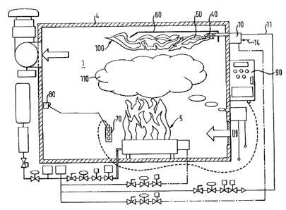
As is apparent from figure 1, a fireplace S is positioned in a burn roozra 1
for simulating, by
way of example, combustion of a sofa disposed on the floor of the bum room. A
gas-air
supply means 10 enters burn zvom 1 just beneath the ceiling 4 thereof, the gas-
air supply
means being conuaected to a gas supply conduit 11, for supply of e.g. pure
propane gas, and to
a fresh air supply 14, and being capable of releasing a gas-air mixture 40
into burn room 1
towards an ignitor 50, for initiating an abrupt flame spreading 100 to
simulate a flashover.
The simulated tlashover is defined by a propagation of flazxtes in at least
two opposite
diree2ions due to ignition on a pair of opposite ignition surfaces, and by
whirling flames due
to the positioning o.f a sheet metal divertor 60 in the path of the flames. In
addition to
fireplace 5 and to flashover 100, smoke 1 l0 may also be introduced into burn
zoom 1.
Gas-air supply means 10 and ign.itor SO naay be activated and deactivated,
respectively,
through manual controller unit 70, which in turn is connected to emergency
stop 80 within
burn room 1 and to operator console 90 outside the burn room 1. For training
firefighters,
initially fireplace 5 is activated and smolte 110 is introduced into burn room
1, respectively
controlled through operator eonsole.90. Subsequezitly, a fast extinguishing
exercise xxtay take
place, during which a simulated flashover l00 may then be initiated according
to the
invention via manual controller unit 70 by a team supervisor. Once, gas-air
supply means 10
and ignitor 50 have been activated through manual controller unit 70 and
controller console
90, ig.aition of the gas-air mixture 40 occurs in the area of ignitor 50, said
ignition occurring
abruptly with a sisnultaaeous propagation of light, heat and pressure with
nearly realistic
conditions.
Referring to fi~-ure 2, a specific arrangement according to the inventiomwill
now be discussed
in detail. The arrangement comprises a gas-air supply means 10 disposed
outside burn roam 1
i.r< an inst<~llation chamber separated by a separating wall 3. The gas-air
supply means 10 itself
comprises, .in downstreann direction of the fresh air ,supplied thereto by a
fresh air supply 14, a
blower 20, a primary heating chamber 30, a pressure attenuation chamber 31
with a gas
manifold 12 disposed therein for a gas 13: a mixing chamber 32, and a chock
flap 33. ~1s .fresh
air is aspirated into primary heating chamber 30 through blower 20 just after
activation of
gas-air supply means 10, the aspirated air is;heated_within primary heating
chsmber 30
through absorption of heat from burn room 1: The heated ais 21 and the gas 13
from ga.S
manifold 12 pass through pressure attenuation chamber 31, which is tapered
from primary
ri
CA 02393203 2002-05-31
heating chamber 30 towards mixing charrabex 32, so that vaporized gas together
with air is
conveyed to miring chamber 32 and is mixed into a combustible gas-air mixture
40 therein,
the gas-air mixture 40, after having passed check klap 33 which prevents it
from being sucked
back into gas-air supply means 10, is exiting mixing chamber 32 to enter bum
room 1. Thm,
gay-air mixture 40 enters burn room 1 from gas-air supply means 10 immediately
after having
passed clZeck flap 33, flowing towards a firM igrxition surface 51 of an
ignitor 50 so that an
abrupt generation of a flame occurs at first ignition surface S l , f1 sheet
metal divertor 60
inverts the flow direction of a portion of gas-air mixture 40 and tktus
directs it to a second
ignition surface 52 of the ignitor 50, producing a similar ignition thereon,
wherein the ignition
on the first ignition surface 51 is only very slightly offset temporarily of
the ignition on the
second ignition surface 52, leading to a zoalastic abnbp: spreading of flames.
In the inventive
dual ignition of gas-air mixture 40 the ceneiation of flames is accelerated as
compared to the
prior art, because there is no need for the g~.~ 13 to "'ruzi after" the air
available in burn room
1. Further, sheet metal divertor 60 provides fox generation of whirls of
.flames.
The features of the invention disclosed in the foregoing description, the
claims and the
drawings .rzaay separately or in any combination thereof be signif cant fox
realising the
invention in ite diverse embodiments.
I /.
CA 02393203 2002-05-31
A 50001
Spaniol, Armin
LIST OF REFERENCE NU~IER~1L5
1 burn room
2 installation chamber
3 separating wall
4 ceiling
fireplace
gas-air supply means
11 gas supply cotaduit
12 gas manifold
13 gas
14 fresh air supply
blower
21 ai.r
primary heating claaznber
1 pressure attenuation chamber
32 mixing chlmber
33 check flap
gas-air mixture
SO igra.itor
51 ignition surface
52 ignition surface
53 current supply line
60 sheet metal divertor
70 manual controller unit
80 emergency stop
90 operator console
100 flashover
110 smoke