Note: Descriptions are shown in the official language in which they were submitted.
CA 02393263 2007-11-13
P30480PCT
AUTOMATED CABLE HANDLING AND TRANSPORT
APPARATUS AND VEHICLE
BACKGROUND OF THE INVENTION
1 o 1. Field of the Invention
The present invention generally relates to cable handling and, more
particularly,
is concerned with an apparatus and vehicle for laying seismic line cable on
the ground,
for retrieving the laid cable from near the ground surface, and, for
transporting the cable
over Iand.
2. Description of the Prior Art
Seismic exploration for oil and gas reservoirs underlying land areas often
requires the laying and later retrieval of very long lengths of seismic line
cable.
Geophone sensors and electronic modules are usually attached at intermittent
points
along the length of the cable. The components, once deployed and connected
together,
fonn a long line, or lines, of seismic sensors, with attached remote
electronic
monitoring packages, and a system of interconnecting cables that carry each
sensors'
output signals back to a seismic recording system.. This attached sensitive
electronic
equipment requires that the seismic line cable be laid carefully. To obtain
accurate
seismic data, the geophone sensors attached to the cable must be placed or
deployed on
the ground surface in a vertical orientation, rather than tilted or sideways.
When
retrieving the seismic line cable fxom the ground after the exploration
activities are
completed, the cable must be held in tension to prevent the entangling of the
sensors,
electronic inodules, and their lead wires with otie another or with the
seismic line cable.
Seismic exploration operations are often conducted in very harsh weather
environments. For example, exploration activities in the Arctic are often
performed at
temperatures as low as minus 50 C. The seismic line cable becomes stiff and
inflexible
at such low temperatures, which makes deploying cable at such temperatures
difficult.
CA 02393263 2002-05-29
WO 02/29948 PCT/US01/11640
Present methods for transporting, deploying and later retrieving, and securing
for further transport, the electronics, the wired arrays of seismic sensors,
and the
associated seismic line cables, are manual and time consuming. The common
method
for transporting and deploying these items is to transport the cables piled
into a basket
or bin mounted on a transport vehicle. The individual packages of electronic
monitoring devices are placed into small bins on the vehicle, and the strings
of sensors
are grouped together by hanging the sensors, and associated interconnecting
wire, by
passing a rod through loops attached to the sensor's interconnecting wire. The
rod is
often in the shape of a "safety pin." The pin closes by latching one end into
a clasp on
the otller end. The sensors are strung onto the pin, while it is open, until
all the sensors,
and their associated intercomlecting wires, are secured by their attached
loops onto the
pin. The pin is then closed. The now full pin is hung onto the vehicle from
hangers
attached along the sides of the transport vehicle.
During the deployment process, the appropriate number of sensor arrays on
pins, electronic module packages, and interconnecting cables are dropped off
the
vehicle at appropriate intervals along the line. Seismic exploration crew
personnel
walk along behind the vehicle and position the electronic module packages,
stretch out
the cables between the electronic modules, unpin the array of sensors and
stretch'them
out along side the interconnecting cable. Each sensor is then installed into
the ground.
The end of the wired sensor array is terminated with an electrical connector
that is then
connected into the electronic package.
When the recording process is complete, the crew personnel again walk along
the line picking up the sensors, grouping them again back onto the pins by
sliding the
end of the pin through the individual loops on the sensor's wire. The seismic
cable is
then rolled up. All of these items are then placed back onto the vehicle to be
transported to the next layout location. Hence, the present method for laying
and
retrieving seismic cable is slow and highly labor intensive.
Consequently, a need exists for an automated cable handling and transport
apparatus and vehicle that is capable of both deploying and retrieving seismic
cable
having sensors and electronic modules _attached intermittently along its
length.
Preferably, the apparatus and vehicle that meets this need can accomplish both
deployment and retrieval of the cable without the constant need for personnel
on the
ground to assist in either action. In addition, the apparatus and vehicle will
preferably
2
CA 02393263 2002-05-29
WO 02/29948 PCT/US01/11640
be capable of maintaining a controlled amount of tension on the cable as it is
being
retrieved so as to prevent entangling of the cable components. Furtller, the
apparatus
and vehicle will preferably provide a means for energizing and testing the
cable and its
electronic components while the cable is being laid, so that mislaid or
defective
components can be relaid or repaired while personnel are still in their
vicinity. Ideally,
such an apparatus and vehicle will also provide a means for maintaining the
stored
cable at a temperature at which it can be easily handled and deployed.
BRIEF SUMMARY OF THE INVENTION
The present invention addresses the aforementioned needs by providing a
mechanized cable laying, retrieval, and transport apparatus and vehicle. In
one
exeinplary application, the seismic line cable includes geophone sensors and
electronic
modules that are interconnected by sensor interconnect lead wires.
A powered reel mouiited on a vehicle is used to lay out, retrieve, and hold
for
transport these three components as a single unit. The result is faster
deployment and
retrieval of the equipment. Also, the number of personnel required to perform
the lay
out and retrieval process is reduced. The number of personnel exposed to
stress and
weather related injuries is also reduced. The present invention permits the
required
seismic crew personnel to ride on the vehicle for operating the controls of
the power
reel unit.
According to one aspect of the invention, an apparatus and vehicle is provided
for retrieving a length of cable from near "the ground surface and
transporting the
retrieved cable. The apparatus and vehicle comprises a vehicle capable of
movement
over land and at least one cable reel is supported by the vehicle for spooling
the cable
thereon as it is being retrieved from near the ground surface. Means is
associated with
the vehicle for tensioning the cable being retrieved.
According to another aspect of the invention, an apparatus and vehicle is
provided for transporting and laying cable on the ground. The apparatus and
vehicle
comprises a vehicle capable of movement over land and at least one cable reel
supported by the vehicle for unspooling the cable therefrom as it is being
laid. Means
may also be associated with the vehicle for forming a channel in the ground
for laying
the unspooled cable therein.
3
CA 02393263 2007-11-13
4
According to a third aspect of the invention, an apparatus and vehicle is
provided
for laying cable on the ground, for retrieving cable from near the ground
surface, and for
transporting the cable. The apparatus and vehicle comprises a vehicle capable
of movement
over land and at least one cable reel supported by the vehicle for unspooling
the cable
therefrom when laying cable, and for spooling the cable thereon when
retrieving cable.
Means may also be associated with the vehicle for forming a channel in the
ground for
laying the unspooled cable therein. A motor is attached to the cable reel for
tensioning the
cable and for rotating the reel to spool the cable thereon. An arm has a first
end pivotally
attached to the vehicle and a second end extending away from the vehicle. The
arm is
pivotally biased upward and away from the ground surface. A guide roller is
rotatably
attached to the second end of the arm. The cable being retrieved passes over
the guide roller
so that the pivotally biased arm assists in tensioning the cable being
retrieved. At least one
sheave is rotatably mounted on the arm. The cable being retrieved passes over
the sheave
for flexing the cable so as to break up and remove any foreign material
adhering to the
cable.
The invention therefore seeks to provide an apparatus and vehicle for
retrieving a
length of cable from near the ground surface and transporting the retrieved
cable, which
comprises:
a vehicle capable of movement over land;
at least two cable reels supported by the vehicle for spooling the cable
thereon as it
is being retrieved from near the ground surface;
at least one cable guide and standoff mounted on the vehicle for guiding the
cable
being retrieved past one or more of the reels and to another one of the reels
for providing an
unobstructed path for spooling the cable thereon; and
means associated with the vehicle for tensioning the cable being retrieved.
The invention further seeks to provide an apparatus and vehicle for
transporting and
laying cable on the ground, which comprises:
a vehicle capable of movement over land;
CA 02393263 2007-11-13
4a
at least two cable reels supported by the vehicle for unspooling the cable
therefrom
as it is being laid;
at least one cable guide and standoff mounted on the vehicle for guiding the
cable
being laid from the reel being unspooled from and past another one or more of
the reels
mounted on the vehicle for providing an unobstructed path for the cable being
laid;
means associated with the vehicle for tensioning the cable being retrieved;
and
means associated with the vehicle for forming a channel in the ground for
laying the
unspoiled cable therein.
BRIEF DESCRIPTION OF THE DRAWING
For a more complete understanding of the present invention, and the advantages
thereof, reference is now made to the following Detailed Description of the
Invention taken
in conjunction with the accompanying drawing, in which:
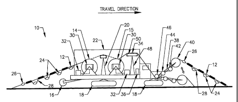
Figure 1 is a side elevation view of the seismic cable handling and transport
apparatus and vehicle of the present invention.
DETAILED DESCRIPTION OF THE INVENTION
The preferred embodiment of the present invention and its advantages are best
understood by referring to the drawing, like numerals being used for like and
corresponding
parts of the various drawing.
In Figure 1, there is shown in side elevation view an apparatus and vehicle,
generally designated 10, for laying or deploying seismic line cable on the
earth surface, for
retrieving the deployed cable from near the ground surface, and for
transporting the cable.
Vehicle 10 both lays and retrieves cable while traveling in the indicated
direction (left to
right) in Figure 1. The seismic line cable 12 is spooled onto, unspooled from,
and
transported by cable reels 14 and 15 mounted on vehicle 10.
CA 02393263 2002-05-29
WO 02/29948 PCT/US01/11640
Cable reels 14 and 15 are of sufficient size to store a minimum of 8000 feet
(2440
meters) of seismic line cable with attached sensors and electronic modules.
Cable reels
14 and 15 are detachably mounted onto vehicle 10 so that full or empty reels
14 or 15
can be easily transferred on and off vehicle 10. Additional cable reels (not
illustrated)
can also be mounted on vehicle 10 if desired.
When laying or deploying cable 12 on snow, sand, or soft earth, depression
wheel 16 towed by vehicle 10 depresses a channel or trough in the earth
covering, into
wliich channel cable 12 is laid. Alternatively, the channel can be depressed
in the soft
earth covering by one of the load bearing vehicle wheels (not illustrated) or
by the
flexible tracks 18 on which the vehicle rides. When laying cable 12 on hard
soil, the
channel for laying cable 12 therein can be formed by a single blade plow (not
shown)
towed by vehicle 10.
Cable guide and standoff 20 is mounted on vehicle 10 between cable reels 14
and 15. When cable 12 is being laid from cable reel 15, cable guide and
standoff 20
guides cable 12 so that the path of cable 12 is unobstructed by cable reel 14
or other
apparatus on vehicle 10, and so that cable 12 follows the desired path to the
ground.
When used to lay cable in very cold environments, enclosure 22 is mounted on
vehicle 10 to enclose cable reels 14 and 15. Enclosure 22 is insulated and
temperature
controlled to maintain spooled cable 12 at a temperature at which it is
sufficiently
flexible for handling and laying. Cable 12 should preferably be maintained at
a
temperature of not less than minus 100 C and below the melt point of water (0
C).
In one exemplary application, seismic line cable 12 includes geophone sensors
24 and electronic modules 26 that are interconnected by sensor interconnect
lead wires
28. Between each pair of sensors 24 and between each electronic module 26 and
adjacent sensor 24, lead wire 28 is taped or otherwise fastened to cable 12.
In other
applications to which the present invention is applicable, seismic line cable
12 may
include other or different components than these. To obtain accurate seismic
data in
seismic exploration using geophone sensors, it is essential that the sensors
be deployed
in a vertical orientation and not tilted, sideways, or upside down. As seen in
Figure 1,
there is sufficient slack in lead wire 28 to permit sensors 24 to hang freely
below cable
12 as cable 12 is being laid. Thus, because sensors 24 hang from cable 12 with
their
bottoms down and tops up, sensors 24 are correctly deployed in a vertical
orientation as
cable 12 is laid in the channel formed in the earth surface.
5
CA 02393263 2002-05-29
WO 02/29948 PCT/US01/11640
Cable reels 14 and 15 contain an electrically conductive slip ring (not
illustrated) so that cable 12 and its electronic modules 26 and sensors 24 can
be
continuously powered and tested as cable 12 is being deployed. The slip ring
preferably contains 4 or 6 conductors. For example, the SERCEL "tilt" test can
be
applied to each sensor 24 after it has been deployed to determine whether it
is oriented
vertically or is tilted from the vertical. If the tilt test reveals that a
sensor is improperly
deployed, corrective action can be taken while personnel are still near the
misplaced
sensor.
Apparatus and vehicle 10 is also equipped for retrieving a length of cable 12
from near the ground surface and transporting the retrieved cable 12. Cable 12
is
retrieved from the front end of vehicle 10, and may be spooled on either cable
reel 14
or reel 15 as it is retrieved. If cable 12 is being spooled onto reel 14,
cable 12 is guided
by cable guide and standoff 20 so that the path of cable 12 (indicated by
dotted lines in
Figure 1) is unobstructed by cable reel 15 or other apparatus on vehicle 10.
Cable reels 14 and 15 are equipped with drive motors 30 for rotating reels 14
and 15 to spool cable 12 thereon and for tensioning the unspooled cable being
retrieved. Drive motors 30 may be electric or hydraulic. A motor power
controller 32
is connected to each motor 30 for automatically controlling the motor power so
that a
constant, operator selectable tension is maintained in cable 12 as it is being
retrieved.
If sufficient tension is not maintained and cable 12 becomes slack as it is
being
retrieved, the geophone sensors 24 and electronic modules 26 can become
entangled
with each other or with lead wires 28 as cable 12 is being spooled, or when
later
unspooled and deployed. A cable tension measuring device 34 measures the
tension in
cable 12 as it is being retrieved and provides appropriate feedback to motor
power
controller 32. Cable tension measuring device 34 may be a running line
tensionometer,
for example.
The cable tension measuring device 34 also provides a measured cable tension
signal to vehicle drive control system 36. When the tension in cable 12 being
retrieved
reaches a predetermined value, vehicle drive control system 36 automatically
slows the
drive speed of vehicle 10 until the cable tension drops sufficiently to resume
normal
vehicle speed. When the tension in cable 12 reaches a second and higher
predetermined value, vehicle drive control system 36 automatically stops the
forward
motion of vehicle 10. Personnel may then deboard vehicle 10 to determine and
correct
6
CA 02393263 2002-05-29
WO 02/29948 PCT/US01/11640
the cause of excessive cable tension, such as, for example, a cable stuck in
ice. After
the cable has been freed, automated retrieval of cable 12 may be resuined.
As an alternative to automatic control, drive motors 30 may be mariually
controlled by the operator of apparatus and vehicle 10. In this case, the
operator may
control either the power to the drive motor 30 or the rotational speed of
cable reel 14 or
so as to maintain constant tension in cable 12 being retrieved. Apparatus and
vehicle 10 may also be equipped so that the operator can control the drive
inotors either
automatically or manually, depending on the terrain he is covering.
As a further means for tensioning cable 12 as it is being retrieved, apparatus
and
10 vehicle 10 is equipped with arm 38 having guide roller or pulley 40 on its
outer end.
The 6pposite end of arm 38 from guide roller 40 is pivotally attached to the
lower front
portion of vehicle 10. Arm 38 is pivotally biased or urged upward, away from
the
ground surface, by one or more mechanical springs or hydraulic or pneumatic
cylinders
(not shown) attached to arm 38. Guide roller 40 has a sufficiently large
diameter to
15 permit the maximum expected tension to be applied to cable 12 without
causing
damage to cable 12. This permits a cable that has become stuck in ice to be
pulled free
by apparatus 10 without manual removal from the ice, and without damage to the
cable.
Cable 12 being retrieved by apparatus and vehicle 12 passes first over guide
roller 40 and then around rotatable sheaves 42, 44, and 46. From lowermost
sheave 46
cable 12 passes back up and over cable guide and standoff 48, and then to a
cable reel
15 or 14. As seen in Figure 1, pivotally biased arm 38 tensions cable 12 as it
is being
retrieved from the ground, and the tension in cable 12 resists the upward
pivotal motion
of arm 38 that is urged by the spring or fluid cylinder (not shown) attached
to ann 38.
As the tension in cable 12 increases, the cable tension force pulls arm 38
down toward
the ground to the position shown in dotted lines in Figure 1. As the cable
tension
decreases, the spring or fluid cylinder attached to arm 38 pivots arm 38 back
up to the
position shown in solid lines in Figure 1. The position of arm 38 thus
provides a visual
indication to the vehicle operator of the amount of tension in cable 12 as it
is being
retrieved. This visual indication assists the operator in efficiently
retrieving the cable,
particularly when the operator manually controls the retrieval rate. The
position of arm
38 can also be used to monitor the cable tension for providing the tension
signal to
vehicle drive control system 36 for slowing and for stopping vehicle 10 at
predetermined levels of cable tension, as described above.
7
CA 02393263 2002-05-29
WO 02/29948 PCT/US01/11640
As cable 12 passes over sheaves 42, 44, and 46, it is flexed in opposite
directions so as to break up and remove any foreign material, such as
accumulated ice
or dirt, from cable 12. The centers of sheaves 42 and 46 are offset from the
center line
of arm 38 so as to increase the degree of wrap, and of flex, of cable 12, and
thus to
facilitate removal of foreign material from cable 12 as it is being retrieved.
A level wind mechanism 50 is built into the top of cable guide and standoff 48
for distributing the cable wind uniformly across the width of cable reel 14 or
15 as
cable 12 is being spooled thereon. Cable wind mechanisms suitable for this
application
are commercially available to the industry.
Apparatus and vehicle 10 should be designed with as low a center of gravity as
possible to permit vehicle 10 to be operated over hilly or mountainous terrain
without
overturning.
The automated cable handling and transport apparatus and vehicle of the
present
invention, and many of its intended advantages, will be understood from the
foregoing
description of an example embodiment, and it will be apparent that, although
the
invention and its advantages have been described in detail, various changes,
substitutions, and alterations may be made in the manner, procedure, and
details thereof
without departing from the spirit and scope of the invention, as defined by
the
appended claims, or sacrificing all of its material advantages, the form
hereinbefore
described being exemplary embodiment thereof.
8