Note: Descriptions are shown in the official language in which they were submitted.
CA 02393347 2002-05-31
WO 01/40330 PCT/US00/13373
SOLUTION FEED OF MULTIPLE CATALYSTS
FIELD OF THE INVENTION
This invention relates to a method to feed multiple catalysts systems into a
polymerization reactor, preferably a gas or slurry phase polymerization
reactor.
BACKGROUND OF THE INVENTION
The demands of polyolefin fabricators are increasingly becoming more and more
specific. In an attempt to meet these demands polyolefin producers are
attempting to create
to more and more specialized polyolefins that have particular product
configurations. One
means to do this comprises using two catalysts in the same reactor to produce
intimately
mixed polymer blends. The difficulty however lies in selecting compatible
catalysts that
will actually work together well and reactor conditions that do not benefit
one catalyst while
hindering another.
15 Mobil, in PCT patent application WO 99/03$99, discloses using a metallocene
type
catalyst and a Ziegler-Natta type catalyst in the same reactor to produce a
bimodal
molecular weight distribution (MWD) high-density polyethylene (HDPE). These
two
catalyst however were fed into the reactor as supported powders.
2o SUMMARY OF THE INVENTION
This invention relates to a method to feed multiple catalysts systems into a
polymerization reactor, preferably a gas or slurry phase polymerization
reactor. The
catalysts, activators and /or catalyst systems are preferably introduced into
the reactor in a
liquid carrier, preferably in solution. The catalysts, activators, catalysts
systems, etc may be
25 combined in different orders and in different amounts. The individual
catalysts or activators
may be introduced into the reactor directly or they may be combined with one
or more other
catalysts and or activators prior to being placed in the reactor. Further the
catalysts,
activators and/or catalyst systems (and the carriers) may be contacted
sequentially, in series
or in parallel. Each catalyst, however, is independently activated.
CA 02393347 2002-05-31
WO 01/40330 PCT/US00/13373
BRIEF DESCRIPTION OF THE DRAWINGS:
Figure 1 is a graphic representation of Illustration 1 below.
Figure 2 is a graphic representation of Illustration 2 below.
Figure 3 is a graphic representation of Illustration 3 below.
Figure 4 is a graphic representation of Illustration 4 below.
Figure S is a graphic representation of Illustration 5 below.
Figure 6 is a graphic representation of Illustration 6 below.
Figure 7 is a graphic representation of Illustration 7 below.
Figure 8 is a graphic representation of Illustration 8 below.
to Figure 9 is a graphic representation of Illustration 9 below.
-2-
CA 02393347 2002-12-20
DETAILED DESCRIPTION OF THE INVENTION:
In a preferred embodiment this invention relates to a method to introduce
multiple
catalysts, activators, or catalyst systems into a polymerization reactor,
preferably a gas phase
reactor. For the purposes of this invention the term "catalyst" refers to a
metal compound
that when combined with an activator polymerizes olefins. For the purposes of
this
invention, the term "catalyst system" refers to the combination of a catalyst
and an activator.
For the purposes of this invention the term "activator" is used
interchangeably with the term
"co-catalyst."
The catalyst system(s), the catalysts and or the activators are preferably
introduced
to into the reactor in one or more liquid carriers, preferably as a solution,
suspension or an
emulsion. For example, in one embodiment, a solution of two catalyst systems
in an alkane
such as pentane, hexane, toluene, isopentane or the like is introduced into
the gas or slurry
phase reactor. In another embodiment the catalyst or activator or both are
contacted in a
liquid carrier with a surfactant to produced an emulsion, then the emulsion is
introduced into
a reactor, such as for example, by spraying the emulsion into a particle lean
zone. (Particle
lean zones are described in U S Patent 5,693, i2-.)
The catalysts, activators, catalysts systems, etc may be combined in different
orders
and in different amounts. In some embodiments the each catalyst may be
contacted with the
same or different activators. Likewise the catalysts may be contacted with
each other first
2o then contacted with the activator(s). Similarly the activator may be
contacted with one
catalyst first with the second catalyst being added thereafter. Further there
may be time
periods, anywhere from 1 second to several days or more between each of the
contacts.
In the various activation and feed schemes possible in the practice of this
invention it
is particularly preferred that each catalyst be independently activated. By
independently
activated is meant that each catalyst has an opportunity to combine or react
with an activator
without having to compete for the activator with another catalyst. For example
in one
embodiment the two catalysts are activated in separate chambers then combined
before
introduction into the reactor. In another embodiment a first catalyst is
activated with an
activator, thereafter a second catalyst is added to the first
catalysts/activator combination
3o and allowed to react/combine with the excess activator. In this embodiment
the second
catalyst is still activated independently from the first. Likewise in another
embodiment two
-3-
CA 02393347 2002-05-31
WO 01/40330 PCT/LTS00/13373
or more catalysts can be activated independently at the same time in the same
solution as
long as sufficient activator for both catalysts to be activated.
In another particularly preferred embodiment, the various catalyst
combinations are
all combined prior to being introduced into the reactor. The catalyst
combinations may be
fed into the reactor from multiple injection points, however it is preferred
that the same
catalyst solution be fed into the reactor through all the injection points.
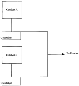
In particular this invention relates to the following illustrations of
combinations. In
the following illustrations, A refers to a catalyst or mixture of catalysts,
and B refers to a
different catalyst or mixture of catalysts. The mixtures of catalysts in A and
B can be the
l0 same catalysts, just in different ratios. Graphic representations of theses
illustrations are
Figures 1-9. Further, it is noted that additional solvents or inert gases may
be added at many
locations.
Illustration 1: A and B plus the activator are mixed off line and then fed to
the
reactor.
Illustration 2: A and B are mixed off line. Activator is added on-line and
then fed
to the reactor.
Illustration 3: A or B is contacted with the activator (off line) and then
either A or B
is added on-line before entering the reactor.
Illustration 4: A or B is contacted with the activator (on-line) and then
either A or B
is added on-line before entering the reactor.
Illustration 5: A and B are each contacted with the activator off line. Then A
+
activator and + cocatalyst are contacted on-line before entering the reactor.
Illustration 6: A and B are each contacted with the activator on-line. Then A
+
activator and B + activator are contacted on-line before entering the reactor.
(This is a
preferred configuration since the ratio of A to B and the ratio of activator
to A and the ratio
of activator to B can be controlled independently.)
Illustration 7: In this example, A or B is contacted with the activator (on-
line) while
a separate solution of either A or B is contacted with activator off line.
Then both stream of
A or B + activator are contacted on-line before entering the reactor.
-4-
CA 02393347 2002-05-31
WO 01/40330 PCT/US00/13373
Illustration 8: A is contacted on-line with B. Then, an activator is fed to on-
line to
the A+B mixture.
Illustration 9: A is activated with activator off line. Then A + activator is
contacted
on-line with B. Then, an activator is fed to in-line to the A+B+ activator
mixture.
Illustration 10: A and B are mixed off line. Then the mixture of Aand B is
contacted on-line with activator, then additional catalyst A is added on line,
thereafter
additional catlayst B is added on-line and then the whole mixture is
introduced into the
reactor.
In any of the above illustrations, a means for mixing and/or creating a
certain
residence time may be employed. For example a mixing blade or screw may be
used to mix
the components or a certain length pipe may be used to obtain a desired
contact or residence
time between the components.
"On-line" means the material described is in a pipe, tube, or vessel which is
directly
or indirectly connected to the reactor system.
"Off line" means the material described is in a pipe, tube, or vessel which is
not
connected to the reactor system.
In a preferred embodiment this invention relates to a method to polymerize
olefins in
a gas-phase reactor wherein at least two catalysts and at least one activator
are introduced in
2o the polymerization reactor in a liquid carrier. In a preferred embodiment
the catalysts and
the activators) are combined in the liquid Garner before being introduced into
the reactor.
In another preferred embodiment the catalysts are combined in a liquid carrier
then
introduced into a channeling means connecting to the reactor and thereafter
the activators)
is introduced into the channeling means at the same or different point as the
catalysts.
In another preferred embodiment the catalysts are combined in a liquid carrier
and
thereafter the activators) is introduced into the liquid carrier.
In another preferred embodiment the liquid carrier containing the catalysts
and the
activators) are placed into an apparatus for introducing the liquid carrier
into the reactor.
In another preferred embodiment the catalysts and liquid carrier are
introduced into
3o the apparatus before the activator is introduced into the apparatus.
-5-
CA 02393347 2002-05-31
WO 01/40330 PCT/US00/13373
In another preferred embodiment the composition comprising the liquid carrier
comprises a liquid stream flowing or sprayed into the reactor.
In another preferred embodiment at least one catalyst, at least one activator
and the
liquid carrier are placed into an apparatus for introduction into the reactor
wherein
additional catalysts) is/are introduced into the apparatus after the first
catalyst and activator
are introduced into the apparatus.
In another preferred embodiment, a first combination comprising at least one
catalyst
in a liquid carrier is introduced into an apparatus connecting to the reactor,
and a second
composition comprising at least one activator in liquid Garner is introduced
into the
apparatus connecting to the reactor, then, after a period of time, a different
catalyst in liquid
Garner is introduced into the apparatus connecting to the reactor, and then
the catalyst-
activator combination is introduced into the reactor.
In another preferred embodiment, at least one catalyst(a) and at least one
activator(a)
are combined in a liquid carrier, and at least one catalyst(b) and at least
one activator(b) are
combined in a liquid Garner, wherein either the catalyst(b) is different from
the catalyst(a) or
the activator (b) is different from the activator(a), thereafter both
combinations are
introduced into an apparatus connecting to the reactor, and, thereafter the
combinations are
introduced into the reactor.
In another preferred embodiment the liquid Garner containing catalyst(b) and
2o activator(b) is introduced into the apparatus connecting to the reactor
after the liquid carrier
containing catalyst(a) and activator(a) is introduced into the apparatus
connecting to the
reactor.
In another preferred embodiment, a first composition comprising at least one
catalyst(a), at least one activator(a) and a liquid carrier is placed in an
apparatus connected
to the reactor, and a second composition comprising at least one catalyst(b),
at least one
activator(b) and a liquid carrier, wherein either the catalyst(b) or the
activator (b) is different
from the catalyst(a) or the activator(a), is introduced into the apparatus
connecting to the
reactor after the first composition is, and thereafter the combined
compositions is introduced
into the reactor.
3o In another preferred embodiment at least one catalyst and the liquid
carrier are
placed into an apparatus for introduction into the reactor wherein additional
catalysts) and
-6-
CA 02393347 2002-05-31
WO 01/40330 PCT/US00/13373
activators) are introduced into the apparatus after the first catalyst is
introduced into the
apparatus.
In another preferred embodiment a first composition comprising at least one
catalyst(a), at least one activator(a) and a liquid carrier is introduced into
an apparatus
feeding into a reactor, and thereafter a second catalyst in a liquid carrier
is added to the
apparatus feeding into the reactor, and thereafter a second activator in a
liquid carrier is
added to the apparatus feeding into the reactor, and thereafter the total
combination is
introduced into the reactor.
More specific preferred embodiments include:
l0 1. Catalyst A could be used as a 0.25 weight % solution in hexane and
Catalyst
B could be used as a 0.50 weight % solution in toluene at molar ratios of B to
A of about 0.7
when the two are activated separately then mixed together or at molar ratios
of B to A of 2.2
to 1.5 when A is activated then B is added.
2. Raising or lowering the reaction temperature to narrow or broaden the
Mw/Mn, respectively.
3. Changing residence time to affect product properties. Large changes can
have significant impact. One to five, preferably four hours residence time
appears to
produce good product properties.
4. Spraying the catalyst into the reactor in such a way as to create a
particle lean
2o zone. A particle lean zone can be created by a 50,000 lb/hr flow of cycle
gas through 6 inch
pipe. The catalyst can be atomized w/ a spray nozzle using nitrogen atomizing
gas.
5. The activator, preferably MMAO 3A can be used at 7 weight % al in
isopentane, hexane or heptane at feed rate sufficient to give an Al/Zr ratio
of 100 to 300.
6. Catalyst A is mixed on-line with MMAO 3A then Catalyst B is added on
line, then the mixture is introduced into the reactor.
7. Catalyst A is mixed on-line with MMAO 3A and Catalyst B is mixed on line
with MMAO 3A thereafter the two activated catalysts are mixed on-line then
introduced
into the reactor.
In one embodiment, a second catalyst is contacted with the first catalyst and
3o activator, such as modified methylalumoxane, in a solvent and just before
the solution is fed
into a gas or slurry phase reactor. In another embodiment a solution of a
first catalyst is
_7_
CA 02393347 2002-05-31
WO 01/40330 PCT/US00/13373
combined with a solution of the second catalyst and the activator then
introduced into the
reactor.
In another embodiment, two or more catalysts are blended together in a slurry
feed
vessel then are contacted with one or more activators, allowed to react for a
specified
amount of time then introduced into the reactor. In another embodiment two or
more
catalysts are contacted in-line and then the activator is fed into the
combined stream then
introduced into the reactor. In another embodiment the catalysts are
independently activated
in-line and then contacted just before delivery to the reactor. Intimate
mixing of the
catalysts and/or the activator is preferred. A static mixer can be used to
achieve intimate
to mixing. In another embodiment the a dilute solution of catalyst is added to
a pre-mixed
batch of catalysts.
Solutions of the catalysts are prepared by taking the catalyst and dissolving
it in any
solvent such as a hydrocarbon, preferably an alkane, toluene, xylene, etc. The
solvent may
first be purified in order to remove any poisons which may affect the catalyst
activity,
15 including any trace water and/or oxygenated compounds. Purification of the
solvent may be
accomplished by using activated alumina and/or activated supported copper
catalyst, for
example. The catalyst is preferably completely dissolved into the solution to
form a
homogeneous solution. Both catalysts may be dissolved into the same solvent,
if desired.
Once the catalysts are in solution, they may be stored indefinitely until use.
Preferred
2o solvents include pentane, hexane, butane, isopentane, cyclohexane, toluene,
xylene, and the
like.
Catalysts:
One of many catalysts or catalysts systems that be used herein include
transition
25 metal catalysts such as one or more bulky ligand metallocene catalysts
and/or one or more
conventional type transition metal catalysts such as one or more Ziegler-Natta
catalysts,
vanadium catalysts and/or chromium catalysts.
For purposes of this invention cyclopentadienyl group is defined to include
indenyls
and fluorenyls.
_g_
CA 02393347 2002-05-31
WO 01/40330 PCT/US00/13373
Bulky Ligand Metallocene Compound:
Bulky ligand metallocene compound (hereinafer also referred to as
metallocenes)
may also be used in the practice of this invention.
Generally, bulky ligand metallocene compounds include half and full sandwich
compounds having one or more bulky ligands bonded to at least one metal atom.
Typical
bulky ligand metallocene compounds are generally described as containing one
or more
bulky ligand(s) and one or more leaving groups) bonded to at least one metal
atom. In one
preferred embodiment, at least one bulky ligands is rl-bonded to the metal
atom, most
preferably r)5-bonded to the metal atom.
to The bulky ligands are generally represented by one or more open, acyclic,
or fused
rings) or ring systems) or a combination thereof. These bulky ligands,
preferably the
rings) or ring systems) are typically composed of atoms selected from Groups
13 to 16
atoms of the Periodic Table of Elements, preferably the atoms are selected
from the group
consisting of carbon, nitrogen, oxygen, silicon, sulfur, phosphorous,
germanium, boron and
15 aluminum or a combination thereof. Most preferably the rings) or ring
systems) are
composed of carbon atoms such as but not limited to those cyclopentadienyl
ligands or
cyclopentadienyl-type ligand structures or other similar functioning ligand
structure such as
a pentadiene, a cyclooctatetraendiyl or an imide ligand. The metal atom is
preferably
selected from Groups 3 through 15 and the lanthanide or actinide series of the
Periodic
2o Table of Elements. Preferably the metal is a transition metal from Groups 4
through 12,
more preferably Groups 4, 5 and 6, and most preferably the transition metal is
from Group
4.
In one embodiment, the bulky ligand metallocene catalyst compounds are
represented by the formula:
L.'~I-BMQn (I)
where M is a metal atom from the Periodic Table of the Elements and may be a
Group 3 to
12 metal or from the lanthanide or actinide series of the Periodic Table of
Elements,
preferably M is a Group 4, 5 or 6 transition metal, more preferably M is a
Group 4 transition
metal, even more preferably M is zirconium, hafnium or titanium. The bulky
ligands, LA
and LB, are open, acyclic or fused rings) or ring systems) and are any
ancillary ligand
system, including unsubstituted or substituted, cyclopentadienyl ligands or
-9-
CA 02393347 2002-05-31
WO 01/40330 PCT/US00/13373
cyclopentadienyl-type ligands, heteroatom substituted and/or heteroatom
containing
cyclopentadienyl-type ligands. Non-limiting examples of bulky ligands include
cyclopentadienyl ligands, cyclopentaphenanthreneyl ligands, indenyl ligands,
benzindenyl
ligands, fluorenyl ligands, octahydrofluorenyl ligands, cyclooctatetraendiyl
ligands,
cyclopentacyclododecene ligands, azenyl ligands, azulene ligands, pentalene
ligands,
phosphoyl ligands, phosphinimine (WO 99/40125), pyrrolyl ligands, pyrozolyl
ligands,
carbazolyl ligands, borabenzene ligands and the like, including hydrogenated
versions
thereof, for example tetrahydroindenyl ligands. In one embodiment, LA and LB
may be any
other ligand structure capable of r)-bonding to M, preferably rl3-bonding to M
and most
1o preferably rls-bonding . In yet another embodiment, the atomic molecular
weight (MW) of
LA or LB exceeds 60 a.m.u., preferably greater than 65 a.m.u.. In another
embodiment, LA
and LB may comprise one or more heteroatoms, for example, nitrogen, silicon,
boron,
germanium, sulfur and phosphorous, in combination with carbon atoms to form an
open,
acyclic, or preferably a fused, ring or ring system, for example, a hetero-
cyclopentadienyl
ancillary ligand. Other LA and LB bulky ligands include but are not limited to
bulky amides,
phosphides, alkoxides, aryloxides, imides, carbolides, borollides, porphyrins,
phthalocyanines, cornns and other polyazomacrocycles. Independently, each L''
and LB
may be the same or different type of bulky ligand that is bonded to M. In one
embodiment
of formula (I) only one of either LA or LB is present.
Independently, each LA and LB may be unsubstituted or substituted with a
combination of substituent groups R. Non-limiting examples of substituent
groups R
include one or more from the group selected from hydrogen, or linear, branched
alkyl
radicals, or alkenyl radicals, alkynyl radicals, cycloalkyl radicals or aryl
radicals, acyl
radicals, aroyl radicals, alkoxy radicals, aryloxy radicals, alkylthio
radicals, dialkylamino
radicals, alkoxycarbonyl radicals, aryloxycarbonyl radicals, carbomoyl
radicals, alkyl- or
dialkyl- carbamoyl radicals, acyloxy radicals, acylamino radicals, aroylamino
radicals,
straight, branched or cyclic, alkylene radicals, or combination thereof. In a
preferred
embodiment, substituent groups R have up to 50 non-hydrogen atoms, preferably
from 1 to
carbon, that can also be substituted with halogens or heteroatoms or the like.
Non-
30 limiting examples of alkyl substituents R include methyl, ethyl, propyl,
butyl, pentyl, hexyl,
cyclopentyl, cyclohexyl, benzyl or phenyl groups and the like, including all
their isomers,
for example tertiary butyl, isopropyl, and the like. Other hydrocarbyl
radicals include
fluoromethyl, fluroethyl, difluroethyl, iodopropyl, bromohexyl, chlorobenzyl
and
hydrocarbyl substituted organometalloid radicals including trimethylsilyl,
trimethylgermyl,
methyldiethylsilyl and the like; and halocarbyl-substituted organometalloid
radicals
-10-
CA 02393347 2002-05-31
WO 01/40330 PCT/US00/13373
including tris(trifluoromethyl)-silyl, methyl-bis(difluoromethyl)silyl,
bromomethyldimethylgermyl and the like; and disubstitiuted boron radicals
including
dimethylboron for example; and disubstituted pnictogen radicals including
dimethylamine,
dimethylphosphine, diphenylamine, methylphenylphosphine, chalcogen radicals
including
methoxy, ethoxy, propoxy, phenoxy, methylsulfide and ethylsulfide. Non-
hydrogen
substituents R include the atoms carbon, silicon, boron, aluminum, nitrogen,
phosphorous,
oxygen, tin, sulfur, germanium and the like, including olefins such as but not
limited to
olefinically unsaturated substituents including vinyl-terminated ligands, for
example but-3-
enyl, prop-2-enyl, hex-5-enyl and the like. Also, at least two R groups,
preferably two
adjacent R groups, are joined to form a ring structure having from 3 to 30
atoms selected
from carbon, nitrogen, oxygen, phosphorous, silicon, germanium, aluminum,
boron or a
combination thereof. Also, a substituent group R group such as 1-butanyl may
form a
carbon sigma bond to the metal M.
Other ligands may be bonded to the metal M, such as at least one leaving group
Q.
In one embodiment, Q is a monoanionic labile ligand having a sigma-bond to M.
Depending on the oxidation state of the metal, the value for n is 0, 1 or 2
such that formula
(I) above represents a neutral bulky ligand metallocene catalyst compound.
Non-limiting examples of Q ligands include weak bases such as amines,
phosphines,
ethers, carboxylates, dimes, hydrocarbyl radicals having from 1 to 20 carbon
atoms,
hydrides or halogens and the like or a combination thereof. In another
embodiment, two or
more Q's form a part of a fused ring or ring system. Other examples of Q
ligands include
those substituents for R as described above and including cyclobutyl,
cyclohexyl, heptyl,
tolyl, trifluromethyl, tetramethylene, pentamethylene, methylidene, methyoxy,
ethyoxy,
propoxy, phenoxy, bis(N-methylanilide), dimethylamide, dimethylphosphide
radicals and
the like.
The two L groups may be bridged together by group A as defined below.
In one embodiment, the bulky ligand metallocene catalyst compounds of the
invention include those of formula (I) where LA and LB are bridged to each
other by at least
one bridging group, A, such that the formula is represented by
L'4ALBMQ" (II)
These bridged compounds represented by formula (II) are known as bridged,
bulky
ligand metallocene catalyst compounds. LA, LB, M, Q and n are as defined
above. Non-
limiting examples of bridging group A include bridging groups containing at
least one
-11-
CA 02393347 2002-12-20
Group 13'to 16 atom, often referred to as a divalent moiety such as but not
limited to at least
one of a carbon, oxygen, nitrogen, silicon, aluminum, boron, germanium and tin
atom or a
combination thereof. Preferably bridging group A contains a carbon, silicon or
germanium
atom, most preferably A contains at least one silicon atom or at least one
carbon atom. The
bridging group A may also contain substituent groups R as defined above
including
halogens and iron. Non-limiting examples of bridging group A may be
represented by
R'ZC, R'zSi, R'ZSi R'zSi, R'zGe, R'P, where R' is independently, a radical
group which is
hydride, hydrocarbyl, substituted hydrocarbyl, halocarbyl, substituted
halocarbyl,
hydrvcarbyl-substituted organometalloid, halocarbyl-substituted
organometalloid,
to disubstituted boron, disubstituted pnictogen, substituted chalcogen, or
halogen or two or
more R' may be joined to form a ring or ring system. In one embodiment, the
bridged,
bulky ligand metallocene catalyst compounds of formula (II) have two or more
bridging
groups A (EP 664 301 B 1 ).
In one embodiment, the bulky ligand metallocene catalyst compounds are those
where the R substituents on the bulky ligands LA and LB of formulas (I) and
(II) are
substituted with the same or different number of substituents on each of.the
bulky ligands.
In another embodiment, the bulky ligands LA and LBOf formulas (I) and (II) are
different
from each other.
Other bulky ligand metallocene catalyst compounds and catalyst systems useful
in
2o the invention may include those described in U.S. Patent Nos. 5,064,802,
5,145,819,
5,149,819, 5,243,001, 5,239,022, 5,276,208, 5,296,434, 5,321,106, 5,329,031,
5,304,614,
5,677,401, 5,723,398, 5,753,578, 5,854,363, 5,856,547 5,858,903, 5,859,158,
5,900,51? and
5,939,503 and PCT publications WO 93/08221, WO 93/08199, WO 95/07140, WO
98/11144, WO 98/41530, WO 98/41529, WO 98/46650, WO 99/02540 and WO 99/14221
and European publications EP-A-0 578 838, EP-A-0 638 595, EP-B-0 513 380, EP-
A1-0
816 372, EP-A2-0 839 834, EP-B1-0 632 819, EP-B1-0 748 821 and EP-B1-0 757
996.
In one embodiment, bulky ligand metallocene catalysts compounds useful in the
invention include bridged heteroatom, mono-bulky ligand metallocene compounds.
These
3o types of catalysts and catalyst systems are described in, for example, PCT
publication WO
92/00333, WO 94/07928, WO 91104257, WO 94103506, W096/00244, WO 97115602 and
WO 99/20637 and U.S. Patent Nos. 5,057,475, 5,096,867, 5,055,438, 5,198,401,
5,227,440
and 5,264,405 and European publication EP-A-0 420 436.
-12-
CA 02393347 2002-12-20
In this embodiment, the bulky ligand metallocene catalyst compound is
represented
by the formula:
LcAJMQ" (III)
where M is a Group 3 to 16 metal atom or a metal selected from the Group of
actinides and
lanthanides of the Periodic Table of Elements, preferably M is a Group 4 to 12
transition
metal, and more preferably M is a Group 4, S or 6 transition metal, and most
preferably M is
a Group 4 transition metal in any oxidation state, especially titanium; L~ is
a substituted or
to unsubstituted bulky ligand bonded to M; J is bonded to M; A is bonded to M
and J; J is a
heteroatom ancillary ligand; and A is a bridging group; Q is a univalent
anionic ligand; and
n is the integer 0,1 or 2. In formula (III) above, L~, A and J form a fused
ring system. In an
embodiment, L~ of formula (III) is as defined above for LA, A, M and Q of
formula (III) are
as defined above in formula (I).
In formula (III), J is a heteroatom containing ligand in which J is an element
with a
coordination number of three from Group 15 or an element with a coordination
number of
two from Group 16 of the Periodic Table of Elements. Preferably J contains a
nitrogen, ,
phosphorus, oxygen or sulfur atom with nitrogen being most preferred.
In an embodiment of the invention, the bulky ligand metallocene catalyst
2o compounds are heterocyclic ligand complexes where the bulky Iigands, the
rings) or
ring system(s), include one or more heteroatoms or a combination thereof. Non-
limiting
examples of heteroatoms include a Group 13 to 16 element, preferably nitrogen,
boron,
sulfur, oxygen, aluminum, silicon, phosphorous and tin. Examples of these
bulky ligand
metallocene catalyst compounds are described in WO 96/33202, WO 96/34021, WO
97/17379 and WO 98/22486 and EP-A1-0 874 005 and U.S. Patent No. 5,637,660,
5,539,124, 5,554,775, 5,756,611, 5,233,049, 5,744,417, and 5,856,258.
In one embodiment, the bulky ligand metallocene catalyst compounds are those
complexes known as transition metal catalysts based on bidentate ligands
containing
3o pyridine or quinoline moieties, such as those described in U.S. Patent No.
6,103,657.
In another embodiment, the bulky ligand metallocene catalyst compounds are
those
described in PCT publications WO 99/01481 and WO 98/42664.
-13-
CA 02393347 2002-12-20
In a preferred embodiment, the bulk3~ ligand metalloc~sne catalyst compound is
a complex of a metal, preferably a transition metal, a bulky Ii,gand,
preferably a
substituted or unsubstituted pi-bonded ligand, and one or more heteroallyl
moieties,
such as those described in U_S. Patent Nos. .5,527,752 and 5,'.147,406 and EP-
B1-0 735
057.
In a particularly preferred embodiznc:nt, the other metal compound or second
metal compound is the bulky ligand metallo~cene catalyst compound is
represented by
the formula:
io T.°I~IQ~(Y~~
where M is a Grcoug 3 to 16 metal, preferably a Group ~4 to 1:2 transition
metal, and
most preferably a Group 4, 5 or 6 transition metal; LD is a bulky Iigand that
is bonded
- to M; each C? is independently bonded to M and (~(Y~ forms a ligand,
preferably a
z5 unicharged polydeatate Iigand; A or Q is a univalent anionic. ligand also
bonded to M;
X is a univalent anionic group when a is 2 ~nr X is a divalent anionic i,'roup
when n is
1; n is 1 or 2, '
In formula (IVY, L and M are as defined above for formula (>'). Q is as
defined
above for formula (I), preferably Q is selected from the group consisting of -
O-, -NR-,
-CRS- and -S-; Y is either C or S; Z is selected from the ,gi~cwp consisting
of -OR, - _
~2~ -~3~ -S~ -5~3~ PR2, -H, and substituted or unsub;ytituted axyl groups,
with
the proviso that when Q is NR- then Z is !:elected from one of the group
consisting of
-Ol~, ..NRZ, -SR, -SiR3, PR2 and H; R is selected from a ~gt~oup containing
carbon,
"' silicon, nitrogen, oxygen, andJor phosphorus, px eferably wh~exe R is 'a
hydrocarbon
25 group containing from 1 to 20 carbon atoms, most preferably an alkyl,
cyeloalkyl, or
an aryl group; n is an integer from 1 to 4, preferably 1 or 2; X is a
univalent anionic
group when ~ is 2 or X is a divalent anionio group when n is 1; preferably X
is a
carbonate, carboxylate, or other heteroallyl moiety describW by the Q, Y and Z
combination.
3o In a particularly preferred embodime~at the bulky li~;and metalloeene
compound iS
represented by the formula:
_14-
CA 02393347 2002-05-31
WO 01/40330 PCT/US00/13373
O
CH3/
- O i
HgC- C~ ~ Zr,, O
O O~ ~~~~ O~ ~~ C Hg
C H3
~CH3
H3C- C CH3 CHg
C H3
Phenoxide Catal~:
Another group of catalysts that may be used in the process of this invention
include
one or more catalysts represented by the following formulae:
R1
R2
O M n Q n-1
R3 ~ R5
R4 __
R1 Qn_2
R2 M n~
O
R5
R5 O
R3
R4 R1 ~ R4
R2 R3
wherein R1 is hydrogen or a C4 to Cioo group, preferably a tertiary alkyl
group, preferably a
C4 toC2o alkyl group, preferably a C4 toC2o tertiary alkyl group, preferably a
neutral C4 to
-1 S
CA 02393347 2002-05-31
WO 01/40330 PCT/US00/13373
Cioo soup and may or may not also be bound to M, and at least one of RZ to R5
is a group
containing a heteroatom, the rest of RZ to RS are independently hydrogen or a
C~ to Cloo
group, preferably a C4 to CZO alkyl group (preferably butyl, isobutyl, pentyl
hexyl, heptyl,
isohexyl, octyl, isooctyl, decyl, nonyl, dodecyl ) and any of RZ to RS also
may or may not be
bound to M,
O is oxygen, M is a group 3 to group 10 transition metal or lanthanide metal,
preferably a
group 4 metal, preferably Ti, Zr or Hf, n is the valence state of the metal M,
preferably 2, 3,
4, or 5, Q is an alkyl, halogen, benzyl, amide, carboxylate, carbamate,
thiolate, hydride or
alkoxide group, or a bond to an R group containing a heteroatom which may be
any of R' to
RS A heteroatom containing group may be any heteroatom or a heteroatom bound
to carbon
silica or another heteroatom. Preferred heteroatoms include boron, aluminum,
silicon,
nitrogen, phosphorus, arsenic, tin, lead, antimony, oxygen, selenium,
tellurium. Particularly
preferred heteroatoms include nitrogen, oxygen, phosphorus, and sulfur. Even
more
particularly preferred heteroatoms include oxygen and nitrogen. The heteroatom
itself may
be directly bound to the phenoxide ring or it may be bound to another atom or
atoms that are
bound to the phenoxide ring. The heteroatom containing group may contain one
or more of
the same or different heteroatoms. Preferred heteroatom groups include imines,
amines,
oxides, phosphines, ethers, ketenes, oxoazolines heterocyclics, oxazolines,
thioethers, and
the like. Particularly preferred heteroatom groups include imines. Any two
adjacent R
groups may form a ring structure, preferably a 5 or 6 membered ring. Likewise
the R
groups may form mufti-ring structures. In one embodiment any two or more R
groups do
not form a 5 membered ring.
These phenoxide catalysts may be activated with activators including alkyl
aluminum compounds (such as diethylaluminum chloride), alumoxanes, modified
alumoxanes, non-coordinating anions, non-coordinating group 13 metal or
metalliod anions,
boranes, borates and the like. For further information on activators please
see the
ACTIVATOR section below.
Conventional-Type Transition Metal Catalysts:
Conventional-type transition metal catalysts are those traditional Ziegler-
Natta,
vanadium and Phillips-type catalysts well known in the art. Such as, for
example Ziegler-
-16-
CA 02393347 2002-12-20
Natta catalysts as described in Ziegler-Natta Catalysts and Polymerizations,
John Boor,
Academic Press, New York, 1979. Examples of conventional-type transition metal
catalysts
are also discussed in U.S. Patent Nos. 4,115,639, 4,077,904, 4,482,687,
4,564,605,
4,721,763, 4,879,359 and 4,960,741.
The conventional-type transition metal catalyst compounds that may be used in
the present
invention include transition metal compounds from Groups 3 to 17, preferably 4
to 12, more
preferably 4 to 6 of the Periodic Table of Elements.
These conventional-type transition metal catalysts may be represented by the
formula: MRX, where M is a metal from Groups 3 to 17, preferably Group 4 to 6,
more
to preferably Group 4, most preferably titanium; R is a halogen or a
hydrocarbyloxy group;
and x is the oxidation state of the metal M. Non-limiting examples of R
include alkoxy,
phenoxy, bromide, chloride and fluoride. Non-limiting examples of conventional-
type
transition metal catalysts where M is titanium include TiCla, TiBr4,
Ti(OC2H5)3C1,
Ti(OC2H5)Cl~, Ti(OCaH9)3C1, Ti(OC3H~)2Clz, Ti(OC2H5)2Br2, TiC13~1/3A1C13 and
1s Ti(OC,2Hz5)C13.
Conventional-type transition metal catalyst compounds based on
magnesiumltitanium electron-donor complexes that are useful in the invention
are described
in, for example, U.S. Patent Nos. 4,302,565 and 4,302,566.
The MgTiCl6 (ethyl acetate),, derivative is particularly preferred.
2o British Patent Application 2,105,355 and U.S. Patent No. 5,317,036,
describes various conventional-type vanadium catalyst
compounds. Non-limiting examples of conventional-type vanadium catalyst
compounds
include vanadyl trihalide, alkoxy halides and alkoxides such as VOC13,
VOC12(OBu) where
Bu =butyl and VO(OCZHS)3; vanadium tetra-halide and vanadium alkoxy halides
such as
2s VCh and VCl3(OBu); vanadium and vanadyl acetyl acetonates and chloroacetyl
acetonates
such as V(AcAc)3 and VOCIz(AcAc) where (AcAc) is an acetyl acetonate. The
preferred
conventional-type vanadium catalyst compounds are VOC13, VCl4 and VOCIz-OR
where R
is a hydrocarbon radical, preferably a C, to C,o aliphatic or aromatic
hydrocarbon radical
such as ethyl, phenyl, isopropyl, butyl, propyl, n-butyl, iso-butyl, tertiary-
butyl, hexyl,
3o cyclohexyl, naphthyl, etc., and vanadium acetyl acetonates.
-17-
CA 02393347 2002-12-20
Conventional-type chromium catalyst compounds, often referred to as Phillips-
type
catalysts, suitable for use in the present invention include Cr03, chromocene,
silyl chromate,
chromyl chloride (Cr01C12), chromium-2-ethyl-hexanoate, chromium
acetylacetonate
(Cr(AcAc)3), and the like. Non-limiting examples are disclosed in U.S. Patent
Nos.
3,709,853, 3,709,954, 3,231,550, 3,242,099 and 4,077,904.
Still other conventional-type transition metal catalyst compounds and catalyst
systems suitable for use in the present invention are disclosed in U.S. Patent
Nos. 4,124,532,
4,302,565, 4,302,566, 4,376,062, 4,379,758, 5,066,737, 5,763,723, 5,849,655,
5,852,144,
Io 5,854,164 and 5,869,585 and published EP-A2 0 416 815 A2 and EP-A1 0 420
436.
Other catalysts may include cationic catalysts such as A1C13, and other
cobalt, iron,
nickel and palladium catalysts well known in the art. See for example U.S.
Patent Nos.
3,487,112, 4,472,559, 4,182,814 and 4,689,437,
Typically, these conventional-type transition metal catalyst compounds
excluding
some conventional-type chromium catalyst compounds are activated with one or
more of the
conventional-type cocatalysts described below.
2o Conventional-Type Cocatalysts:
Conventional-type cocatalyst compounds for the above conventional-type
transition
metal catalyst compounds may be represented by the formula M3M4vX2cR3b~ ,
wherein M3
is a metal from Group 1 to 3 and 12 to 13 of the Periodic Table of Elements;
M4 is a metal
of Group 1 of the Periodic Table of Elements; v is a number from 0 to l; each
X2 is any
halogen; c is a number from 0 to 3; each R3 is a monovalent hydrocarbon
radical or
hydrogen; b is a number from 1 to 4; and wherein b minus c is at least 1.
Other
conventional-type organometallic cocatalyst compounds for the above
conventional-type
transition metal catalysts have the formula M3R3k, where M3 is a Group IA,
I.IA, IIB or IIIA
metal, such as lithium, sodium, beryllium, barium, boron, aluminum, zinc,
cadmium, and
3o gallium; k equals 1, 2 or 3 depending upon the valency of M3 which valency
in turn
-18-
CA 02393347 2002-12-20
normally depends upon the particular Group to which M3 belongs; and each R;
may be any
monovalent hydrocarbon radical.
Non-limiting examples of conventional-type organometallic cocatalyst compounds
useful with the conventional-type catalyst compounds described above include
methyllithium, butyllithium, dihexylmercury, butylmagnesium, diethylcadmium,
benzylpotassium, diethylzinc, tri-n-butylaluminum, diisobutyl ethylboron,
diethylcadmium,
di-n-butylzinc and tri-n-amylboron, and, in particular, the aluminum alkyls,
such as tri-
hexyl-aluminum, triethylaluminum, trimethylaluminum, and tri-isobutylaluminum.
Other
conventional-type cocatalyst compounds include mono-organohalides and hydrides
of
1o Group 2 metals, and mono- or di-organohalides and hydrides of Group 3 and
13 metals.
Non-limiting examples of such conventional-type cocatalyst compounds include
di-
isobutylaluminum bromide, isobutylboron dichloride, methyl magnesium chloride,
ethylberyllium chloride, ethylcalcium bromide, di-isobutylaluminum hydride,
methylcadmium hydride, diethylboron hydride, hexylberyllium hydride,
dipropylboron
hydride, octylmagnesium hydride, butylzinc hydride, dichloroboron hydride, di-
bromo-
aluminum hydride and bromocadmium hydride. Conventional-type organometallic
cocatalyst compounds are known to those in the art and a more complete
discussion of these
compounds may be found in U.S. Patent Nos. 3,221,002 and 5,093,415.
Activators:
The catalysts, preferably the metallocene catalysts described herein, are
preferably
combined with one or more activators to form olefin polymerization catalyst
systems.
Preferred activators include alkyl aluminum compounds (such as diethylaluminum
chloride), alumoxanes, modified alumoxanes, non-coordinating anions, non-
coordinating
group 13 metal or metalloid anions, boranes, borates and the like. It is
within the scope of
this invention to use alumoxane or modified alumoxane as an activator, and/or
to also use
ionizing activators, neutral or ionic, such as tri {n-butyl) ammonium tetrakis
(pentafluorophenyl) boron or a trisperfluorophenyl boron metalloid precursor
which ionize
3o the neutral metallocene compound. Other useful compounds include triphenyl
boron,
-19-
CA 02393347 2002-12-20
triethyl boron, tri-n-butyl ammonium tetraethylborate, triaryl borane and the
like. Other
useful compounds include aluminate salts as well.
In a preferred embodiment modified alumoxanes are combined with the catalysts
to .
form a catalyst system. In a preferred embodiment MMA03A (modified methyl
aiumoxane
in heptane, commercially available from Akzo Chemicals, Inc. under the trade
name
Modified Methylalumoxane type 3A , covered under patent number US 5,041,584)
is
combined with the first and second metal compounds to form a catalyst system.
There are a variety of methods for preparing alumoxane and modified
alumoxanes,
non-limiting examples of which are described in U.S. Patent No. 4,665,208,
4,952,540,
l0 5,091,352, 5,206,199, 5,204,419, 4,874,734, 4,924,018, 4,908,463,
4,968,827, 5,308,815,
5,329,032, 5,248,801, 5,235,081, 5,157,137, 5,103,031, 5,391,793, 5,391,529,
5,041,584
5,693,838, 5,731,253, 5,041,584 and 5,731,451 and European publications EP-A-0
561 476,
EP-B1-0 279 586 and EP-A-0 594-218, and PCT publication WO 94/10180.
Ionizing compounds may contain an active proton, or some other cation
associated
with but not coordinated to or only loosely coordinated to the remaining ion
of the ionizing
compound. Such compounds and the like are described in European publications
EP-A-0
570 982, EP-A-0 520 732, EP-A-0 495 375, EP-A-0 426 637, EP-A-500 944, EP-A-0
277
003 and EP-A-0 277 004, and U.S. Patent Nos. 5,153,157, 5,198,401, 5,066,741,
5,206,197,
5,241,025, 5,387,568, 5,384,299, 5,502,124 and 5,643,847.
Other activators include those described in PCT publication WO
98/07515 such as tris (2, 2', 2"- nonafluorobiphenyl) fluoroaluminate, which
is fully
incorporated herein by reference. Combinations of activators are also
contemplated by the
invention, for example, alumoxanes and ionizing activators in combinations,
see for
example, PCT publications WO 94/07928 and WO 95/14044 and U.S. Patent Nos.
5,153,157 and 5,453,410, Also, methods of activiation such as using radiation
and the
like are also contemplated as activators for the purposes of this invention.
When two different catalysts are used, the first and second catalyst compounds
may
be combined at molar ratios of 1:1000 to 1000:1, preferably 1:99 to 99:I,
preferably 10:90
to 90:10, more preferably 20:80 to 80:20, more preferably 30:70 to 70:30, more
preferably
-20-
CA 02393347 2002-05-31
WO 01/40330 PCT/US00/13373
40:60 to 60:40. The particular ratio chosen will depend on the end product
desired and/or
the method of activation. One practical method to determine which ratio is
best to obtain
the desired polymer is to start with a 1:1 ratio, measure the desired property
in the product
produced and adjust the ratio accordingly.
Multi-component catalyst systems with similar activity decay rates provide a
route
for olefin polymerization in which the effects of catalyst residence time in
the reactor can be
mitigated. The catalysts preferably have a decay rate that is similar as
measured by a decay
model, be it first or higher order. The decay rates or alternatively, the
catalyst half lives, are
preferably within about 40% of each other, more preferably about 20% of each
other, and
most preferably about 10 to 0% of each other. 0% would mean essentially the
same.
It is recognized that the decay characteristics can be affected by
temperature,
monomer pressure, comonomer type and concentration, hydrogen,
additives/modifiers/other
catalysts, catalyst poisons or impurities in the gas stream, presence of
condensing agents or
operation in condensing-mode.
A corollary to this is that one or both of the catalysts can have a fast decay
such that
they are relatively insensitive to residence time effects in the normal range
of reactor
operation. One can calculate how much the decay rates can differ between
catalysts based
upon their respective decay rates, in order that the variation of polymer
properties in the
reactor is relatively small when there are changes in residence time.
2o In another embodiment the first catalyst is selected because when used
alone it
produces a high weight average molecular weight polymer (such as for example
above 100,
000, preferably above 150, 000, preferably above 200,000, preferably above
250,000, more
preferably above 300,000) and the second catalyst is selected because when
used alone it
produces a low molecular weight polymer (such as for example below 80,000,
preferably
below 70,000, preferably below 60,000, more preferably below 50,000, more
preferably
below 40,000, more preferably below 30,000, more preferably below 20,000 and
above
5,000, more preferably below 20,000 and above 10,000).
When three or more catalysts are used multi component catalyst polymerization
split
can be estimated and controlled by perturbing the feed rate of one or both of
the catalyst
3o feed rates to the polymerization reactor and measuring the change in
polymer production
rate. The invention is especially useful when the catalysts are
indistinguishable elementally
-21-
CA 02393347 2002-05-31
WO 01/40330 PCT/US00/13373
but can be used with other systems. It is especially applicable in systems
where the relative
amounts of each catalyst can be easily varied such as for solution feed or
hybrid solution
feed.
The change in catalyst feed is less than 40%, preferably less than 15% and
most
preferably about 5 to 10%. There are accompanying changes in the polymer split
composition, however, these are relatively small and may be inconsequential as
the time-
frame for observing changes in production rate may be short relative to
residence time in the
reactor. The change in polymer composition is diluted.
The production rate need not line out, but can be estimated mathematically
when it is
1o about 30 to 80% of its final value based upon theoretical response of CSTR
(continuous
stirred tank reactor) to a step change.
The simplest case is for a catalyst with very fast decay so residence time
effects are
inconsequential (although decay can easily be dealt with using a simple
formula). As an
example, let catalyst A and B be fed at a 50:50 rate, producing 10,000 pph of
resin. Increase
catalyst A by 10% and hold B constant so the feed split is now 55:50. The
production rate
increases from 10,000 to 10,500 pph. The difference of 5000 pph is
attributable to the 10%
increase of catalyst A, so the initial amount of resin produce by A was 5000
pph and its new
value is 5500 pph. The initial polymer split was 50:50 and the new split is
55:50. (In this
example, the catalysts were taken to be equally active, but the equation work
for other
sytems.
The catalyst feed rate or one or both catalysts can be constantly perturbed by
small
amounts continuously around the aim split (back and forth) so that the net
resin composition
is always around the aim split. A step change is made and the response
measured. The
system performance can include an update term based on measured split to
account for
variations in catalyst productivity and decay.
Catalyst productivity models including the effects of temperature, residence
time,
monomer partial pressure, comonomer type and concentration, hydrogen
concentration,
impurities, inerts such as isopentane, and/or operation in or close to
condensing mode can be
used for each component of a separate addition, mufti-component polymerization
system for
polymerization fraction split control. In response to changes in variables,
the feed rates of
component catalysts can be adjusted. For example, a change in residence time
can be
-22-
CA 02393347 2002-05-31
WO 01/40330 PCT/US00/13373
compensated for by forward control that automatically adjusts the catalysts
feed rates to a
new aim value. Effects of temperature, partial pressure and other variables
can also be
compensated in a feed forward fashion.
The models can also be used for process control based upon measured polymer
split
fractions. Ethylene partial pressure, for example could be adjusted by the
models based
upon the measured split. The concentration of an inert that affects the
productivity of one
catalyst more than the other could also be adjusted (like isopentane due
presumably to its
tempered cooling effect).
Most commonly, the catalyst feed rates would be adjusted to move the measured
polymer split back to aim. The effects of catalyst decay and residence time
are part of the
model, so the even the use of catalysts with significant or different decay
rates can be
controlled.
The instant invention is applicable to gas phase polymerization with solution
or
liquid feed.
In general the combined catalysts and the activator are combined in ratios of
about
1000:1 to about 0.5:1. In a preferred embodiment the catalysts and the
activator are
combined in a ratio of about 300:1 to about 1:1, preferably about 150:1 to
about 1:1, for
boranes, borates, aluminates, etc. the ratio is preferably about 1:1 to about
10:1 and for alkyl
aluminum compounds (such as diethylaluminum chloride combined with water) the
ratio is
2o preferably about 0.5:1 to about 10:1.
Polymerization Process:
The catalysts, activators and catalyst systems described above are suitable
for use in
any polymerization process, including solution, gas or slurry processes or a
combination
thereof, most preferably a gas or slurry phase process.
In one embodiment, this invention is directed toward the polymerization or
copolymerization reactions involving the polymerization of one or more
monomers having
from 2 to 30 carbon atoms, preferably 2-12 carbon atoms, and more preferably 2
to 8 carbon
atoms. The invention is particularly well suited to the copolymerization
reactions involving
the polymerization of one or more olefin monomers of ethylene, propylene,
butene-1,
pentene-1, 4-methyl-pentene-1, hexene-l, octene-1, decene-l, 3-methyl-pentene-
1, 3,5,5-
-23-
CA 02393347 2002-12-20
trimethyl-hexene-1 and cyclic olefins or a combination thereof. Other monomers
can
include vinyl monomers, diolefins such as. dienes, polyenes, norbornene,
norbornadiene
monomers. Preferably a copolymer of ethylene is produced, where the comonomer
is at
least one alpha-olefin having from 4 to 15 carbon atoms, preferably from 4 to
12 carbon
atoms, more preferably from 4 to 8 carbon atoms and most preferably from 4 to
7 carbon
atoms. In an alternate embodiment, the geminally disubstituted olefins
disclosed in WO
98/37109 may be polymerized or copolymerized using the invention herein
described.
In another embodiment ethylene or propylene is polymerized with at least two
different comonomers to form a terpolymer. The preferred comonomers are a
combination
to of alpha-olefin monomers having 4 to 10 carbon atoms, more preferably 4 to
8 carbon
atoms, optionally with at least one dime monomer. The preferred terpolymers
include the
combinations such as ethylene/butene-1/hexene-1, ethylene/propylene/butene-1,
propylene/ethylene/hexene-1, ethylene/propylene/ norbornene and the like.
In a particularly preferred embodiment the process of the invention relates to
the
polymerization of ethylene and at least one comonomer having from 4 to 8
carbon atoms,
preferably 4 to 7 carbon atoms. Particularly, the comonomers are butene-1, 4-
methyl-
pentene-1, hexene-1 and octene-1, the most preferred being hexene-1 and/or
butene-1.
Typically in a gas phase polymerization process a continuous cycle is employed
where in one part of the cycle of a reactor system, a cycling gas stream,
otherwise known as
2o a recycle stream or fluidizing medium, is heated in the reactor by the heat
of polymerization.
This heat is removed from the recycle composition in another part of the cycle
by a cooling
system external to the reactor. Generally, in a gas fluidized bed process for
producing
polymers, a gaseous stream containing one or more monomers is continuously
cycled
through a fluidized bed in the presence of a catalyst under reactive
conditions. The gaseous
stream is withdrawn from the fluidized bed and recycled back into the reactor.
Simultaneously, polymer product is withdrawn from the reactor and fresh
monomer is added
to replace the polymerized monomer. (See for example U.S. Patent Nos.
4,543,399,
4,588,790, 5,028,670, 5,317,036, 5,352,749, 5,405,922, 5,436,304, 5,453,471,
5,462,999,
5,616,661 and 5,668,228. )
3o The reactor pressure in a gas phase process may vary from about 10 psig (69
kPa) to
about 500 psig (3448 kPa), preferably in the range of from about 100 psig (690
kPa) to
-24-
CA 02393347 2002-12-20
about 400 psig (2759 kPa), preferably in the range of from about 200 psig
(1379 kPa) to
about 400 psig (2759 kPa), more preferably in the range of from about 250 psig
(1724 lc.Pa)
to about 350 psig (2414 kPa).
The reactor temperature in the gas phase process may vary from about
30°C to about
120°C, preferably from about 60°C to about 115°C, more
preferably in the range of from
about 75°C to 110°C, and most preferably in the range of from
about 85°C to about 110°C.
Altering the polymerization temperature can also be used as a tool to alter
the final polymer
product properties.
The productivity of the catalysts) or catalyst systems) is influenced by the
main
l0 monomer partial pressure. The preferred mole percent of the main monomer,
ethylene or
propylene, preferably ethylene, is from about 25 to 90 mole percent and the
monomer partial
pressure is in the range of from about 75 psia (S 17 kPa) to about 300 psia
(2069 l:Pa), which
are typical conditions in a gas phase polymerization process. In one
embodiment the
ethylene partial pressure is about 220 to 240 psi (1517- 1653 kPa). In another
embodiment
i 5 the molar ratio of hexene to ethylene ins the reactor is 0.03:1 to 0.08:1.
In a preferred embodiment, the reactor utilized in the present invention and
the
process of the invention produce greater than 500 lbs of polymer per hour (227
Kg/hr) to
about 200,000 lbs/hr (90,900 Kg/hr) or higher of polymer, preferably greater
than 1000
ibs/hr (455 Kg/hr), more preferably greater than 10,000 lbs/hr (4540 Kghir),
even more
20 preferably greater than 25,000 lbs/hr (11,300 Kg/hr), still more preferably
greater than
35,000 lbs/hr (15,900 Kglhr), still even more preferably greater than 50,000
lbs/hr (22,700
Kg/hr) and most preferably greater than 65,000 Ibs/hr (29,000 Kg/hr) to
greater than
100,000 Ibs/hr (45;500 Kg/hr).
Other gas phase processes contemplated by the process of the invention include
25 those described in U.S. Patent Nos. 5,627,242, 5,665,818 and 5,677,375, and
European
publications EP-A- 0 794 200, EP-A- 0 802 202 and EP-B- 634 421.
A slurry polymerization process generally uses pressures in the range of from
about
1 to about 50 atmospheres and even greater and temperatures in the range of
0°C to about
30 120°C. In a slurry polymerization, a suspension of solid,
particulate polymer is formed in a
liquid polymerization diluent medium to which ethylene and comonomers and
often
-25-
CA 02393347 2002-12-20
hydrogen along with catalyst are added. The suspension including diluent is
intermittently
or continuously removed from the reactor where the volatile components are
separated from
the polymer and recycled, optionally after a distillation, to the reactor. The
liquid diluent
employed in the polymerization medium is typically an alkane having from 3 to
7 carbon
atoms, preferably a branched atkane. The medium employed should be liquid
under the
conditions of polymerization and relatively inert. When a propane medium is
used the
process must be operated above the reaction diluent critical temperature and
pressure.
Preferably, a hexane or an isobutane medium is employed.
In one embodiment, a preferred polymerization technique of the invention is
referred
Io to as a particle form polymerization, or a slurry process where the
temperature is kept below
the temperature at which the polymer goes into solution. Such technique is
well known in
the art, and described in for instance U.S. Patent No. 3,248,179.
The preferred temperature in the particle form process is within the
range of about 185°F (85°C) to about 230°F (
110°C). Two preferred polymerization
methods for the slurry process are those employing a loop reactor and those
utilizing a
plurality of stirred reactors in series, parallel, or combinations thereof.
Non-limiting
examples of slung processes include continuous loop or stirred tank processes.
Also, other
examples of slurry processes are described in U.S. Patent No. 4,613,484,
2o In another embodiment, the slurry process is carried out continuously in a
loop
reactor. The catalyst (s) and/or activators) as a solution, as a suspension,
as an emulsion, or
as a slurry in isobutane or as a dry free flowing powder is injected regularly
to the reactor
loop, which is itself filled with circulating slurry of growing polymer
particles in a diluent of
isobutane containing monomer and comonomer. Hydrogen, optionally, may be added
as a
molecular weight control. The reactor is maintained at pressure of about 525
psig to 625
psig {3620 kPa to 4309 kPa) and at a temperature in the range of about 140
°F to about 220
°F (about 60 °C to about 104 °C) depending on the desired
polymer density. Reaction heat
is removed through the loop wall since much of the reactor is in the form of a
double-
jacketed pipe. The slurry is allowed to exit the reactor at regular intervals
or continuously to
a heated low pressure flash vessel, rotary dryer and a nitrogen purge column
in sequence for
-26-
CA 02393347 2002-12-20
removal of the isobutane diluent and all unreacted monomer and comonomers. The
resulting hydrocarbon free powder is then compounded for use in various
applications.
In another embodiment the reactor used in the slurry process of the invention
is
capable of and the process of the invention is producing greater than 2000 lbs
of polymer
per hour (907 Kglhr), more preferably greater than 5000 lbs/hr (2268 Kg/hr),
and most
preferably greater than 10,000 lbs/hr (4540 Kg/hr). In another embodiment the
slurry
reactor used in the process of the invention is producing greater than 15,000
lbs of polymer
per hour (6804 Kg/hr), preferably greater than 25,000 lbs/hr (11,340 Kg/hr) to
about
100,000 lbs/hr (45,500 Kg/hr).
to In another embodiment in the slurry process of the invention the total
reactor
pressure is in the range of from 400 psig (2758 kPa) to 800 prig (5516 kPa),
preferably 4S0
psig (3103 kPa) to about 700 psig (4827 kPa), more preferably 500 psig (3448
kPa) to about
650 psig (4482 kPa), most preferably from about 525 psig (3620 kPa) to 62S
psig (4309
kPa).
In yet another embodiment in the slurry process of the invention the
concentration of
ethylene in the reactor liquid medium is in the range of from about 1 to 10
weight percent,
preferably from about 2 to about 7 weight percent, more preferably from about
2.S to about
6 weight percent, most preferably from about 3 to about 6 weight percent.
A preferred process of the invention is where the process, preferably a slurry
or gas
2o phase process is operated in the absence of or essentially free of any
scavengers, such as
triethylaluminum, trimethylaluminum, tri-isobutylaluminum and tri-n-
hexylaluminum and
diethyl aluminum chloride, dibutyl zinc and the like. This preferred process
is described in
PCT publication WO 96/08520 and U.S. Patent No. 5,712,352.
In another preferred embodiment the one or all of the catalysts are combined
with up
to 10 weight % of a metal stearate, (preferably a aluminum stearate, more
preferably
aluminum distearate) based upon the weight of the catalyst system (or its
components), any
support and the stearate. In an alternate embodiment a solution of the metal
stearate is fed
into the reactor. In another embodiment the metal stearate is mixed with the
catalyst and fed
into the reactor separately. These agents may be mixed with the catalyst or
may be fed into
the reactor in a solution or a slurry with or without the catalyst system or
its components.
-27-
CA 02393347 2002-12-20
In another preferred embodiment the supported catalysts combined with the
activators are tumbled with 1 weight % of aluminum distearate or 2 weight % of
an antistat,
such as a methoxylated amine, such as Witco's Kemamine M AS-900 from ICI
Specialties in
Bloomington Delaware. In another embodiment, a supported catalyst system of
component
is combined with 2 to 3 weight % of a metal stearate, based upon the weight of
the catalyst
system (or its components), any support and the stearate.
More information on using aluminum stearate type additives may be found in
U.S. Patent No. 6,031,120.
In a preferred embodiment a slurry of the stearate in mineral oil is
introduced into
1 o the reactor separately from the metal compounds and or the activators.
Experience with solution catalyst has shown that a smooth MMAO flow rate is
better
for maintaining a low static level in the reactor. Also, quick changes in MMAO
flow, either
up or down, are preferably avoided or else extreme static levels could be
generated.
Reduced static levels will result in reduced agglomeration and sheeting
episodes.
15 While solution or slurry is a referenced embodiment, the catalyst and/or
the activator
may be placed on, deposited on, contacted with, incorporated within, adsorbed,
or absorbed
in a support. Typically the support can be of any of the solid, porous
supports, including
microporous supports. Typical support materials include talc; inorganic oxides
such as
silica, magnesium chloride, alumina, silica-alumina; polymeric supports such
as
2o polyethylene, polypropylene, polystyrene, cross-linked polystyrene; and the
like. Preferably
the support is used in finely divided form. Prior to use the support is
preferably partially or
completely dehydrated. The dehydration may be done physically by calcining or
by
chemically converting all or part of the active hydroxyls. For more
information on how to
support catalysts please see US 4,808,561 which discloses how to support a
metallocene
25 catalyst system. The techniques used therein are generally applicable for
this invention.
In another embodiment NMR, (or other) equipment is used to analyze the feed
stream
composition of the catalyst solution prior to injecting it into a
polymerization reactor. The
information is then used to control individual feed streams and thus the final
polymer
product.
3o In another embodiment a selective poison is added to the polymerization
which
selectively deactivates one of the catalysts in a controlled manner and
thereby controls the
-28-
CA 02393347 2002-05-31
WO 01/40330 PCT/US00/13373
active split of polymer being produced. Preferred selective poisons include
carbon dioxide,
carbon monoxide, various internal olefins and dimes, oxygen, Lewis bases such
as ethers,
esters, and various amines.
In another embodiment if catalyst from one feeder is lost or interrupted
during the
independent (but mixed) addition of two or more catalyst to a polymerization,
the other
catalyst feeders) are stopped within about 30 minutes, preferably within about
5 minutes,
most preferably within about 2 minutes or immediately. The reactor may be
killed or mini-
killed if residence effects are expected to drive the split off specification
when the reactor is
operating with no fresh catalyst feed and catalyst feed cannot be restored
within a specific
1o period of time dependent upon the performance of the catalysts.
The present invention should be applicable to gas phase polymerization with
solution
feed or hybrid solution feed system.
In a preferred embodiment, the polymer produced herein has an IZl (as measured
by
ASTM 1238, condition E, at 190 °C) of 20 g/ 10 min or less, preferably
15 g/ 10 min or less,
preferably 12 or less, more preferably between 5 and 10 g/10 min, more
preferably between
6 and 8 g/10 min and a melt flow index "MIR" of IZI/I2 (as measured by ASTM
1238,
condition E and F, at 190 °C) of 80 or more, preferably 90 or more,
preferably 100 or more,
preferably 125 or more.
In another embodiment, the polymer has an I21 (as measured by ASTM 1238,
2o condition E, at 190 °C) of 20 g/ 10 min or less, preferably 15 g/ 10
min or less, preferably
12 or less, more preferably between 5 and 10 g/10 min, more preferably between
6 and 8
g/10 min and a melt flow index "MIR" of Izl/I2 (as measured by ASTM 1238,
condition E,
at 190 °C) of 80 or more, preferably 90 or more, preferably 100 or
more, preferably 125 or
more and has one or more of the following properties in addition:
(a) Mw/Mn of between 15 and 80, preferably between 20 and 60, preferably
between 20
and 40;
(b) an Mw of 180,000 or more, preferably 200,000 or more, preferably 250,000
or more,
preferably 300,000 or more;
(c) a density (as measured by ASTM 2839) of 0.94 to 0.970 g/cm3; preferably
0.945 to
0.965 g/cm3; preferably 0.950 to 0.960 g/cm3;
-29-
CA 02393347 2002-05-31
WO 01/40330 PCT/CTS00/13373
(e) a residual metal content of 2.0 ppm transition metal or less, preferably
1.8 ppm
transition metal or less, preferably 1.6 ppm transition metal or less,
preferably 1.5 ppm
transition metal or less, preferably 2.0 ppm or less of group 4 metal,
preferably 1.8 ppm or
less of group 4 metal, preferably 1.6 ppm or less of group 4 metal, preferably
1.5 ppm or
less of group 4 metal, preferably 2.0 ppm or less zirconium, preferably 1.8
ppm or less
zirconium, preferably 1.6 ppm or less zirconium, preferably 1.5 ppm or less
zirconium(as
measured by Inductively Coupled Plasma Optical Emission Spectroscopy run
against
commercially available standards, where the sample is heated so as to fully
decompose all
organics and the solvent comprises nitric acid and, if any support is present,
another acid to
to dissolve any support (such as hydrofluoric acid to dissolve silica
supports) is present;
(f) 35 weight percent or more high weight average molecular weight component,
as
measured by size-exclusion chromatography, preferably 40% or more. In a
particularly
preferred embodiment the higher molecular weight fraction is present at
between 35 and 70
weight %, more preferably between 40 and 60 weight %.
Molecular weight (Mw and Mn) are measured as described below in the examples
section.
In another embodiment, the polymer product has a residual metal content of 2.0
ppm
transition metal or less, preferably 1.8 ppm transition metal or less,
preferably 1.6 ppm
transition metal or less, preferably 1.5 ppm transition metal or less,
preferably 2.0 ppm or
less of group 4 metal, preferably 1.8 ppm or less of group 4 metal, preferably
1.6 ppm or
less of group 4 metal, preferably 1.5 ppm or less of group 4 metal, preferably
2.0 ppm or
less zirconium, preferably 1.8 ppm or less zirconium, preferably 1.6 ppm or
less zirconium,
preferably 1.5 ppm or less zirconium(as measured by Inductively Coupled Plasma
Optical
Emission Spectroscopy run against commercially available standards, where the
sample is
heated so as to fully decompose all organics and the solvent comprises nitric
acid and, if any
support is present, another acid to dissolve any support (such as hydrofluoric
acid to
dissolve silica supports) is present.
In another embodiment, the polymer product has a residual nitrogen content of
2.0
ppm or less, preferably 1.8 ppm nitrogen or less, preferably 1.6 ppm nitrogen
or less,
preferably 1.5 ppm nitrogen or less (as measured by Inductively Coupled Plasma
Optical
Emission Spectroscopy run against commercially available standards, where the
sample is
-30-
CA 02393347 2002-05-31
WO 01/40330 PCT/US00/13373
heated so as to fully decompose all organics and the solvent comprises nitric
acid and, if any
support is present, another acid to dissolve any support (such as hydrofluoric
acid to
dissolve silica supports) is present.
In another embodiment, the polymer produced herein has a composition
distribution
breadth index (CDBI) of 70 or more, preferably 75 or more even more preferably
80 or
more. Composition distribution breadth index is a means of measuring the
distribution of
comonomer between polymer chains in a given sample. CDBI is measured according
to the
procedure in WO 93/03093, published February 18, 1993, provided that fractions
having a
molecular weight below 10,000 Mn are ignored for the calculation.
to In a preferred embodiment, the polyolefin recovered typically has a melt
index as
measured by ASTM D-1238, Condition E, at 190°C of 3000 g/10 min or
less. In a preferred
embodiment the polyolefin is ethylene homopolymer or copolymer. In a preferred
embodiment for certain applications, such as films, molded article and the
like a melt index
of 100 g/10 min or less is preferred. For some films and molded article a melt
index of 10
15 g/10 min or less is preferred.
In another aspect, this invention relates to a polymer produced in a single
reactor
having an IZ1 of less than or equal to 20 g/ 10 min and an melt index ratio
(MIR = I2~/IZ) of
greater than or equal to 80. I21 and Iz are measured according to ASTM 1238,
condition E at
190 °C.
2o In another aspect, this invention relates to films produced from the
polymer
produced herein.
In a preferred embodiment, the catalyst system described above is used to make
a
polyethylene having a density of between 0.94 and 0.970 g/cm3 (as measured by
ASTM
1505) and a melt index of 0.5 or less g/lOmin or less (as measured by ASTM D-
1238,
25 Condition E, at 190°C).
Polyethylene having a melt index of between 0.01 to 10 dg/min is preferably
produced.
Polyolefms, particularly polyethylenes, having a density of 0.89 to 0.97g/cm3
can be
produced using this invention. In particular polyethylenes having a density of
0.910 to
3o 0.965, preferably 0.915 to 0.960, preferably 0.920 to 0.955 can be
produced. In some
-31-
CA 02393347 2002-05-31
WO 01/40330 PCT/US00/13373
embodiments, a density of 0.915 to 0.940 g/cm3 would be preferred, in other
embodiments
densities of 0.930 to 0.970 g/cm3 are preferred.
The melt index (and other properties) of the polymer produced may be changed
by
manipulating the polymerization system by:
1) changing the amount of the first catalyst in the polymerization system,
and/or
2) changing the amount of the second catalyst in the polymerization system,
and/or
3) adding or removing hydrogen to or from the polymerization process; and/or
4) changing the amount of liquid and/or gas that is withdrawn and/or purged
from the
process; and/or
5) changing the amount and/or composition of a recovered liquid and/or
recovered gas
returned to the polymerization process, said recovered liquid or recovered gas
being
recovered from polymer discharged from the polymerization process; and/or
6) using a hydrogenation catalyst in the polymerization process; and/or
7) changing the polymerization temperature; and/or
8) changing the ethylene partial pressure in the polymerization process;
and/or
9) changing the ethylene to comonomer ratio in the polymerization process;
and/or
10) changing the activator to transition metal ratio in the activation
sequence, and/or
11) changing the length of time that activator contacts the transition metal
in the
activation sequence, and/or
12) varying the amount of the activators) and/or the two or more catalysts
that are
introduced into the feed apparatus, and/or
13) altering the point at which the multiple catalysts and or activators are
added to the
feed apparatus, and/or
14) altering the residence times of the multiple catalysts in the feed
apparatus, and/or
15) altering the flow rate of the carrier, and/or
16) altering the temperature of the mixture in the feed apparatus.
In a preferred embodiment the hydrogen concentration in the reactor is about
200-
2000 ppm, preferably 250-1900 ppm, preferably 300-1800 ppm, preferably 350-
1700 ppm,
-32-
CA 02393347 2002-05-31
WO 01/40330 PCT/US00/13373
preferably 400-1600 ppm, preferably 500-1500 ppm, preferably 500-1400 ppm,
preferably
500-1200 ppm, preferably 600-1200 ppm, preferably 700-1100 ppm, more
preferably 800-
1000 ppm.
The polyolefins then can be made into films, molded articles (including
pipes),
sheets, wire and cable coating and the like. The films may be formed by any of
the
conventional techniques known in the art including extrusion, co-extrusion,
lamination,
blowing and casting. The film may be obtained by the flat film or tubular
process which
may be followed by orientation in an uniaxial direction or in two mutually
perpendicular
directions in the plane of the film to the same or different extents.
Orientation may be to the
to same extent in both directions or may be to different extents. Particularly
preferred methods
to form the polymers into films include extrusion or coextrusion on a blown or
cast film
line.
The films produced may further contain additives such as slip, antiblock,
antioxidants, pigments, fillers, antifog, UV stabilizers, antistats, polymer
processing aids,
15 neutralizers, lubricants, surfactants, pigments, dyes and nucleating
agents. Preferred
additives include silicon dioxide, synthetic silica, titanium dioxide,
polydimethylsiloxane,
calcium carbonate, metal stearates, calcium stearate, zinc stearate, talc,
BaS04,
diatomaceous earth, wax, carbon black, flame retarding additives, low
molecular weight
resins, hydrocarbon resins, glass beads and the like. The additives may be
present in the
2o typically effective amounts well known in the art, such as 0.001 weight %
to 10 weight %.
-33-
CA 02393347 2002-05-31
WO 01/40330 PCT/US00/13373
EXAMPLES:
Mn and Mw were measured by gel permeation chromatography on a waters
150°C GPC
instrument equipped with differential refraction index detectors. The GPC
columns were
calibrated by running a series of molecular weight standards and the molecular
weights were
calculated using Mark Houwink coefficients for the polymer in question.
MWD = M~,,/Mn
Density was measured according to ASTM D 1505.
Melt Index (MI) IZ was measured according to ASTM D-1238, Condition E, at
190°C.
1o IZl was measured according to ASTM D-1238, Condition F, at 190°C.
Melt Index Ratio (MIR) is the ratio of I21 over IZ.
Weight % comonomer was measured by proton NMR.
"PPH" is pounds per hour. "mPPH" is millipounds per hour. "ppmw" is parts per
million
by weight.
CATALYST 1
Indenyl zirconium tris pivalate, a bulky ligand metallocene compound, also
represented by formula IV, can be prepared by performing the following general
reactions:
(1) Zr(NEt2)4 + IndH ~ IndZr(NEtZ)3 + EtZNH
(2) IndZr(NEt2)3 + 3 (CH3)3CCOZH ~ IndZr[OZCC(CH3)]3 + EtZNH
Where Ind = indenyl and Et is ethyl.
Preparation of Catalyst 1
Preparation 1 wt% Catalyst 1 in Hexane Solution
All procedures were performed in a glove box.
1. Transfer 1 liter of purified hexane into a 1 L Erlenmeyer flask equipped
with a Teflon
coated stir bar.
2. Add 6.67 grams of indenyl zirconium tris pivalate dried powder.
3. Place solution on magnetic agitator and stir for 15 minutes. All of the
solids go into
solution.
-34-
CA 02393347 2002-05-31
WO 01/40330 PCT/US00/13373
4. Pour solution into a clean, purged 1-L Whitey sample cylinder, labeled, and
removed
from glovebox and place in holding area until use in operation.
CATALYST2
Catalyst 2 is [1-(2-Pyridyl)N-1-Methylethyl][1-N-2,6-Diisopropylphenyl Amido]
Zirconium Tribenzyl and was produced as follows:
Preparation Of [1-(2-P~rid~)N-1-Meth,~~l~l-N-2,6-Diisopropylphen~lAmine
H3C~ ~ H3
C
II
In a dry box, 22.45 mmol (6.34 g) 2-acetylpyridine(2,6-diisopropylphenylimine)
were charged to a 250 mL round bottom flask equipped with a stir bar and
septa. The flask
was sealed, removed from the dry box and placed under nitrogen purge. Dry
toluene (50
15 mL) was added and stirred to dissolve the ligand. The vessel was chilled to
0° C in a wet ice
bath. Trimethyl aluminum (Aldrich, 2.0 M in toluene) was added dropwise over
ten
minutes. The temperature of the reaction was not allowed to exceed 10°
C. When addition
of the trimethyl aluminum was complete, the mixture was allowed to warm slowly
to room
temperature, and then was then placed in an oil bath and heated to 40°
C for 25 minutes.
2o The vessel was removed from the oil bath and placed in an ice bath. A
dropping funnel
containing 100 mL of 5% KOH was attached to the flask. The caustic was charged
to the
reaction dropwise over a 1 hour span. The mixture was transferred to a
separatory funnel.
The aqueous layer was removed. The solvent layer was washed with 100 mL water
then 100
mL brine. The red-brown liquid product was dried over Na2S04, vacuum stripped
and
25 placed under high vacuum over night.
80 mL of red-brown liquid was transferred to a 200 mL Schlenk flask equipped
with a stir bar. A distillation head with a dry ice condenser was attached to
the flask. The
-35-
CA 02393347 2002-05-31
WO 01/40330 PCT/US00/13373
mixture was vacuum distilled yielding approximately 70 g of dark yellow
viscous liquid
product.
Preparation Of [1-(2-Pyridyl)N-1-Methyleth~l[1-N-2,6-Diisopropylphenyl Amidol
Zirconium Tribenzyl
H3C~ CH3 CH3
C \H3C
\ / H3C
Zr
CHz ~ ~ ' 'CH CH3
2
CH2
In a darkened room and darkened dry box, 5.0 mmol (1.45 g) of the ligand made
in
Example 1 were charged to a 100 mL Schlenk tube equipped with a stir bar. The
ligand was
dissolved in 5 mL of toluene. To a second vessel equipped with a stir bar was
charged 5.5
mmol (2.Sg) tetrabenzyl zirconium and 10 mL toluene.
The ligand solution was transferred into the tetrabenzyl zirconium solution.
The
vessel was covered with foil and allowed to stir at room temperature in the
dry box. After 6
hours at room temperature 80 mL dry hexane was added to the reaction solution
and
allowed to stir overnight. The reaction mixture was filtered through a medium
porosity frit
with approximately 2g pale yellow solids collected.
-36-
CA 02393347 2002-05-31
WO 01/40330 PCT/US00/13373
CATALYST 3
Catalyst 3 is tetrahydroindenyl zirconium tris pivalate" a bulky ligand
metallocene
compound, also represented by formula IV, can be prepared by performing the
following
general reactions:
(1) Zr(NEt2)4 + IndH ~ IndZr(NEt2)3 + Et2NH
(2) IndZr(NEt2)3 + 3 (CH3)3CCOZH -~ IndZr[OZCC(CH3)]3 + EtZNH
Where Ind = tetrahydroindenyl and Et is ethyl.
l0 Example 1:
An ethylene hexene copolymer was produced in a 14-inch (35.6 cm) pilot plant
scale
gas phase reactor operating at 85° C and 350 psig (2.4 MPa) total
reactor pressure having a
water cooled heat exchanger. The reactor was equipped with a plenum having
about 1,600
PPH of recycle gas flow. (The plenum is a device used to create a particle
lean zone in a
fluidized bed gas-phase reactor. See US Patent 5,693,727.) A tapered catalyst
injection
nozzle having a 0.041 inch (0.10 cm) hole size was position in the plenum gas
flow. Prior to
starting the catalyst feed, ethylene pressure was about 220 psia (1.5 MPa), 1-
hexene
concentration was about 0.6 mol % and hydrogen concentration was about 0.25
mol %.
Nitrogen was fed to the reactor as a make-up gas at about 5-8 PPH. The
catalyst solution
was a 1:1 molar ratio of Catalyst 2:Catalyst 3 catalyst in a toluene solution.
Catalyst feed
was started at 13 cc's per hour, which was sufficient to give the desired
production rate of
17 lbs/hr(kg/hr7.7). The catalyst and co-catalyst (MMAO-3A, 1 wt % Aluminum)
were
mixed in line prior to passing through the injection nozzle into the fluidized
bed. MMAO to
catalyst was controlled so that the AI:Zr molar ratio was 300:1. 5.0 lbs/hr
(2.3 kg/hr)
Nitrogen and 20 lbs/hr (9.1 kg/hr) 1-hexene were also fed to the injection
nozzle. A
bimodal polymer having nominal 0.43 dg/min (I21) and 0.942 g/cc properties was
obtained.
The resin average particle size was 0.023 inches (0.58 cm). A residual
zirconium of 2.2
ppm was measured by x-ray fluorescence.
-37-
CA 02393347 2002-05-31
WO 01/40330 PCT/US00/13373
Example 2 - Three Catalyst Component Examples:
Example ZA. Preparation of a two-catalyst component solution
1. In a glovebox, weighed out 688.4 g of purified toluene into a 1 L
Erlenmeyer flask
equipped with a Teflon coated stirbar.
2. Added 3.45 g of Catalyst 2 catalyst and 0.43 g of bis n-
butylcyclopentadienyl
zirconium dichloride, placed on agitator and stirred for 15 minutes. All
solids went
into solution.
3. Charged 1 L of catalyst solution to a Whitey sample cylinder, labeled,
removed from
glovebox and placed into holding area for operations.
Example 2B. Preparation of third catalyst component solution
1. In a glovebox, weighed out 647 g of purified hexane into a 1 L Erlenmeyer
flask
equipped with a Teflon coated stirbar.
2. Added 0.81 g of indenyl zirconium tris-pivalate catalyst from Boulder
Scientific,
placed on agitator and stirred for 15 minutes. All solids went into solution.
3. Charged 1 L of catalyst solution to a Whitey sample cylinder, labeled,
removed from
glovebox and placed into holding area for operations.
Example 2C. Production of Resin containing three catalyst components
An ethylene hexene copolymer was produced in a 14-inch (35.6 cm) pilot plant
scale
gas phase reactor operating at 85° C and 350 psig (2.4 MPa) total
reactor pressure having a
water cooled heat exchanger. Ethylene was fed to the reactor at a rate of
about 38 pounds
per hour (17.2 kg/hr), hexene was fed to the reactor at a rate of about 0.3
pounds per hour
(0.14 kg/hr) and hydrogen was fed to the reactor at a rate of 8 mPPH. Nitrogen
was fed to
the reactor as a make-up gas at about 4-8 PPH. The production rate was about
30 PPH. The
3o reactor was equipped with a plenum having about 1,600 PPH of recycle gas
flow. (The
plenum is a device used to create a particle lean zone in a fluidized bed gas-
phase reactor.
-3 8-
CA 02393347 2002-12-20
See US Patent 5,693,727.) A tapered catalyst injection nozzle having a 0.055
inch (0.14
cm) hole size was position in the plenum gas flow. Catalyst from Example B was
contacted
in-line with 1-hexene and 3.55 % A1 (MMAO-3A) in hexane for approximately 30
minutes
before joining a stream of the mixed catalyst from Example A. The catalyst
ratio was kept
at 2.2:1 (Example B : Example A). The MMAO-3A was controlled so that the
overall AI:Zr
molar ratio was 230:1. Nitrogen was also fed to the injection nozzle as needed
to maintain a
stable average particle size.
A broad molecular weight distribution polymer having nominal 4.69 dg/min Iz,,
0.02
dg/min I2, 234 IZ,/IZ ratio and 0.94$ g/cc properties was obtained. A residual
zirconium of
1.18 ppmw was calculated based on a reactor mass balance. The polymer was
characterized
by SEC (See Figure 1) and determined to be approximately 53 % high molecular
weight
polymer. The final polymer had an Mn of 12,222, an Mw of 372,661 and an Mw/Mn
of
30.49.
1s
As is apparent form the foregoing general description and the specific
embodiments, while forms of the invention have been illustrated and described,
various
modifications can be made without departing from the spirit and scope of the
invention.
Accordingly it is not intended that the invention be limited thereby.
-39-