Note: Descriptions are shown in the official language in which they were submitted.
CA 02393509 2002-06-04
WO 01/47135 PCT/US00/34774
PROGRAMMABLE MATCHED FILTER SEARCHER FOR
MULTIPLE PILOT SEARCHING
BACKGROUND OF THE INVENTION
I. Field of the Invention
The present invention relates to communications. More particularly, the
present invention relates to a novel and improved method and apparatus for
detecting one or more pilot signals with a programmable matched filter
searcher.
II. Description of the Related Art
Pseudorandom noise (PN) sequences are commonly used in direct
sequence spread spectrum communication systems such as that described in the
IS-95 over the air interface standard and its derivatives such as IS-95-A and
ANSI J-STD-008 (referred to hereafter collectively as the IS-95 standard)
promulgated by the Telecommunication Industry Association (TIA) and used
primarily within cellular telecommunications systems. The IS-95 standard
incorporates code division multiple access (CDMA) signal modulation
techniques to conduct multiple communications simultaneously over the same
RF bandwidth. When combined with comprehensive power control,
conducting multiple communications over the same bandwidth increases the
total number of calls and other communications that can be conducted in a
wireless communication system by, among other things, increasing the
frequency reuse in comparison to other wireless telecommunication
technologies. The use of CDMA techniques in a multiple access communication
system is disclosed in U.S. Patent No. 4,901,307, entitled "SPREAD SPECTRUM
COMMUNICATION SYSTEM USING SATELLITE OR TERRESTRIAL
REPEATERS", and U.S. Patent No. 5,103,459, entitled "SYSTEM AND METHOD
FOR GENERATING SIGNAL WAVEFORMS IN A CDMA CELLULAR
TELEPHONE SYSTEM", both of which are assigned to the assignee of the
present invention and incorporated by reference herein.
FIG. 1 provides a highly simplified illustration of a cellular telephone
system configured in accordance with the use of the IS-95 standard. During
operation, a set of subscriber units 10a - d conduct wireless communication by
CA 02393509 2002-06-04
WO 01/47135 PCT/US00/34774
2
establishing one or more RF interfaces with one or more base stations 12a - d
using CDMA modulated RF signals. Each RF interface between a base station
12 and a subscriber unit 10 is comprised of a forward link signal transmitted
from the base station 12, and a reverse link signal transmitted from the
subscriber unit. Using these RF interfaces, a communication with another user
is generally conducted by way of mobile telephone switching office (MTSO) 14
and public switch telephone network (PSTN) 16. The links between base
stations 12, MTSO 14 and PSTN 16 are usually formed via wire line
connections, although the use of additional RF or microwave links is also
known.
Each subscriber unit 10 communicates with one or more base stations 12
by utilizing a rake receiver. A RAKE receiver is described in U.S. Patent No.
5,109,390 entitled "DIVERSITY RECEIVER IN A CDMA CELLULAR
TELEPHONE SYSTEM", assigned to the assignee of the present invention and
incorporated herein by reference. A rake receiver is typically made up of one
or
more searchers for locating direct and multipath pilot from neighboring base
stations, and two or more fingers for receiving and combining information
signals from those base stations. Searchers are described in co-pending U.S.
Patent Application 08/316,177, entitled "MULTIPATH SEARCH PROCESSOR
FOR SPREAD SPECTRUM MULTIPLE ACCESS COMMUNICATION
SYSTEMS", filed September 30, 1994, assigned to the assignee of the present
invention and incorporated herein by reference.
Inherent in the design of direct sequence spread spectrum
communication systems is the requirement that a receiver must align its PN
sequences to those of the base station. In IS-95, each base station and
subscriber
unit uses the exact same PN sequences. A base station distinguishes itself
from
other base stations by inserting a unique offset in the generation of its PN
sequences. In IS-95 systems, all base stations are offset by an integer
multiple of
64 chips. A subscriber unit communicates with a base station by assigning at
least one finger to that base station. An assigned finger must insert the
appropriate offset into its PN sequence in order to communicate with that base
station. It is also possible to differentiate base stations by using unique PN
sequences for each rather than offsets of the same PN sequence. In this case,
fingers would adjust their PN generators to produce the appropriate PN
sequence for the base station to which it is assigned.
Subscriber units locate base stations by utilizing searchers. A fast,
flexible, and hardware efficient matched filter searcher is described in co-
pending U.S. Patent Application 09/283,010 (hereinafter the '010 application),
CA 02393509 2002-06-04
WO 01/47135 PCT/US00/34774
3
entitled "PROGRAMMABLE MATCHED FILTER SEARCHER", filed March 31,
1999, assigned to the assignee of the present invention and incorporated
herein
by reference. This searcher adds flexibility to the parallel computation
features
of a matched filter, allowing a variable number of coherent accumulations and
a
variable number of non-coherent accumulations to be performed at high speed
for a wide range of search hypotheses in a resource efficient manner. Many of
the features of this searcher are applicable to the present invention as well,
and
will be described in greater detail below.
The FCC has mandated that by October 2001, carriers must provide the
location of a cell phone user making an emergency 911 call to within 125
meters. In addition to providing mandated location services, wireless carriers
are interested in providing revenue-generating location-based services such as
roadside assistance, traffic updates, yellow page directory assistance, and
the
like.
A variety of approaches can be taken to solve this problem, among them
are solutions based on the Global Positioning System (GPS). The Global
Positioning System comprises a constellation of 24 satellites. Each satellite
contains a clock that is kept synchronized to GPS time by monitoring ground
stations. GPS receivers on the ground can use signals received from several
GPS satellites to determine position and time.
Each GPS satellite transmits two microwave carriers: a 1575.42 MHz L1
carrier which carries the signals used for Standard Positioning Service (SPS),
and a 1227.60 MHz L2 carrier which carries signals needed for Precise
Positioning Service (PPS). PPS is used by governmental agencies and allows a
higher degree of accuracy in positioning.
The Ll carrier is modulated by the Coarse Acquisition (C/A) code, a
1023-chip pseudorandom code transmitted at 1.023 Mcps that is used for civil
position location services. Each GPS satellite has its own C/A code that
repeats
every 1 ms. The code used for PPS is a 10.23 MHz code that is 267 days in
length.
Each GPS satellite has a different C/A code that belongs to a family of
codes called Gold codes. Gold codes are used because the cross-correlation
between them is small. Each GPS satellite generates a unique C/A code
sequence. A GPS receiver reproduces the C/A sequence for a particular
satellite and correlates it with the received signal over all possible
offsets.
When correlation is found, the start time of the code is referred to as the
time of
arrival (TOA) at the receiver. This TOA is a measure of the range to the
satellite, with an offset due to any mismatch between the receiver clock and
CA 02393509 2002-06-04
WO 01/47135 PCT/US00/34774
4
GPS time. The TOA is also referred to as the pseudorange. Once the
pseudoranges from each of 4 satellites have been obtained, a position fix can
be
computed by solving for the intersection of 4 spheres. Using 4 satellites
allows
the receiver clock uncertainty to be cancelled out.
GPS position location can be done based solely on signals received from
GPS satellites, as just described, but can also be accomplished using a hybrid
scheme. Such hybrid schemes are often useful when additional information is
available to reduce the complexity of the position location task. One example
is
a wireless network, where the base station can provide information to limit
the
required search windows or can provide accurate time corresponding to GPS
time. One such system is described in co-pending U.S. Patent Application
09/187,939, entitled "MOBILE COMMUNICATION SYSTEM WITH POSITION
DETECTION TO FACILITATE HARD HANDOFF", filed November 6, 1998,
assigned to the assignee of the present invention and incorporated herein by
reference.
There is commonality in the hardware needed to search for CDMA pilots
(or the like) and that needed for position location (whether pure GPS or some
hybrid). However, in contrast to the single pilot code systems such as that
described in IS-95, multiple pilot code systems such as GPS would inherently
benefit from the ability to search more than one pilot code simultaneously.
Many devices, such as subscriber unit 10 in FIG. 1, will need to perform both
types of searching during their normal course of operation. There is a need in
the art for a fast, flexible, hardware-efficient searcher that combines CDMA
pilot searching with multiple pilot searching for systems such as GPS position
location.
SUMMARY OF THE INVENTION
A novel and improved method and apparatus for searching is described.
This searcher combines the ability to search multiple offsets of single
pilots,
such as those found in the IS-95 system, with the ability to search multiple
pilots, such as those found in a GPS location determination system. Both types
of searching can be done in a single architecture combining the parallel
computation features of a matched filter with the flexibility of allowing a
variable number of coherent accumulations and a variable number of non-
coherent accumulations to be performed at high speed for a wide range of
CA 02393509 2002-06-04
WO 01/47135 PCT/US00/34774
search hypotheses in a resource efficient manner. This invention allows for
parallel use of the matched filter structure in a time-sliced manner to search
multiple windows. In addition, the searcher allows for optional independent
Walsh decovering for each search window. The time-sharing approach allows
5 for optional frequency searching of any offset.
I and Q channel data are despread utilizing a matched filter structure.
The matched filter structure can be configured as one large matched filter
with
a single I/Q data input, or it can be configured to accept a plurality of
signals,
essentially breaking the matched filter into a plurality of smaller matched
filters. The plurality of inputs can be independent signals from a variety of
sources, such as multiple satellites in a GPS network.
The in-phase and quadrature amplitudes from the matched filter are
delivered to coherent accumulators to sum for a programmable duration of
time. This coherent accumulation can occur for the entire matched filter
structure, or multiple accumulations can be generated based on the subsets of
the matched filter associated with each of a plurality of input signals. These
coherent accumulations are available for further processing in a device such
as
a DSP. For single pilot searching, the coherent amplitude accumulations are
squared and summed to produce an energy measurement. The energy
measurement is accumulated for a second programmable time to perform non-
coherent accumulation. The resulting value is used to determine the likelihood
of a pilot signal at that offset.
Each matched filter structure comprises an N-value shift register for
receiving data, a programmable bank of taps to perform despreading and
optional Walsh decovering, and an adder structure to sum the resulting filter
tap calculations. The matched filter structure can optionally be used in a
time-
sharing manner to search multiple windows as dictated by a multiplexor which
supplies various streams of tap values for despreading (with optional Walsh
decovering included in the tap values). In addition, an optional phase rotator
can be added to apply multiplexed phase values to perform frequency
searching. Every cycle the matched filter structure produces an intermediate
calculation for a particular offset (with optional Walsh decovering and
optional
phase rotation) which includes N calculations based on the data in the shift
register.
CA 02393509 2002-06-04
WO 01/47135 PCT/US00/34774
6
BRIEF DESCRIPTION OF THE DRAWINGS
The features, objects, and advantages of the present invention will
become more apparent from the detailed description set forth below when
taken in conjunction with the drawings in which like reference characters
identify correspondingly throughout and wherein:
FIG. 1 is a block diagram of cellular telephone system;
FIG. 2 is a block diagram of a prior art programmable matched filter
searcher;
FIG. 3 depicts a QPSK despreader;
FIG. 4 depicts a BPSK despreader;
FIG. 5 is a block diagram of a matched filter searcher configured in
accordance with the present invention; and
FIGS. 6A-6D contain a more detailed block diagram configured in
accordance with the present invention;
DETAILED DESCRIPTION OF THE PREFERRED
EMBODIMENTS
FIG. 2 depicts a simplified diagram of a searcher configured in
accordance with the invention disclosed in the '010 application. The features
of
the '010 invention are reiterated here, followed by the modifications to be
made
in accordance with the present invention. One of the novel features of the
present invention is to allow the increased functionality of GPS searching
while
utilizing an architecture that is very similar to that described in the '010
application.
I and Q data (Hereinafter DI and DQ) enters shift registers 400 and 402,
respectively. The size of the matched filter component of this invention is
given
by N, the number of memory locations in the shift registers. Data is
continually
loaded and shifted through the shift registers at a constant rate. In the
exemplary embodiment, data is loaded in at twice the chip rate. This allows
for
searching on every chip and half-chip boundary.
The data in shift registers 400 and 402 are then correlated with N-bit
portions of the I and Q PN sequences (Hereinafter PNI and PNQ) which are
CA 02393509 2002-06-04
WO 01/47135 PCT/US00/34774
7
loaded into despreader 410. To despread a QPSK spread pilot signal, complex
despreading is performed: (DI + jDQ).( PN, + jPNQ) _ (DIPN, + DQPNQ) + j(DQPNI
- DIPNQ). FIG. 3 depicts one stage of the N-stage QPSK despreader. One of the
N values of DI is multiplied by the corresponding tap value PN, in multiplier
600 and by the corresponding tap value PNQ in multiplier 604. Similarly, D~ is
multiplied by tap values PNI and PNQ in multipliers 604 and 606, respectively.
The output of multipliers 600 and 606 are summed in adder 608. The output of
multiplier 604 is subtracted from the output of multiplier 602 in adder 610.
The
output of adder 608 is the despread I value. The output of adder 610 is the
despread Q value. Since there are N stages, there will be N such complex
results.
The present invention is also useful for BPSK despreading. In this case
there is only a single PN sequence to correlate with, which provides the tap
values for both the I and Q in despreader 410. The circuit shown in FIG. 3 can
be used as is with the single PN sequence being delivered to both PN, and PNQ.
FIG. 4 shows the simplified despreader which can be used if only BPSK
despreading is desired. D, and DQ are multiplied by the PN sequence in
multipliers 612 and 614 respectively. The results are summed in adder 616 to
produce the despread I value. The output of multiplier 612 is subtracted from
multiplier 614 in adder 618 to produce the despread Q value. Again there are N
stages, so there will be N complex results.
Although FIG. 3 and FIG. 4 show multipliers in use, simplifications are
known in the art. When the tap values are binary, as they are in the exemplary
embodiment, consisting only of the values 1 and -1, and the proper data format
is chosen for D, and DQ, the despreading step can be accomplished utilizing
only
XOR gates and multiplexors (details not shown).
The N despread I and despread Q values produced in despreader 410 are
summed respectively in summers 420 and 422. Each time the data in shift
registers 400 and 402 change, new sums are calculated in summers 420 and 422,
as shown in FIG. 2. Each sum is an N-chip coherent accumulation of a
particular offset. The process is repeated for a programmable number of cycles
without changing the tap values in despreader 410. For example, in the
exemplary embodiment the matched filter size, N, is 64. Suppose a search
window size, L, of 64 and a coherent accumulation, C, of 256 was desired. In
this case, the tap values appropriate for the beginning of the window are
loaded
into despreader 410 and data is cycled through the shift register, producing
results from summers 420 and 422 each cycle.
CA 02393509 2002-06-04
WO 01/47135 PCT/US00/34774
8
Each result is loaded into coherent accumulators 430 and 432,
respectively. These accumulators accommodate multiple accumulations at a
single time. In the exemplary embodiment, they are RAM based. During each
cycle, the appropriate partial accumulation is retrieved, added to the output
of
either summer 420 or 422, and the resultant partial accumulation is stored
again
in the RAM. In our example, when 64 cycles have passed, the first 64 I and Q
sums have been loaded into accumulators 430 and 432. Each of these sums
corresponds to a C of 64, since that is the width of the matched filter.
During this time, a new set of tap values for despreader 410 has been
calculated. These are calculated so that the same 64 offset hypotheses that
were
tested in the first pass can be tested again. If the tap values were not
changed, a
new offset would be tested with each cycle until the entire PN space had been
searched (like a standard matched filter searcher). The matched filter
procedure is repeated again for another 64 cycles. This time, each result is
summed with the corresponding partial accumulation for its offset as stored in
accumulators 430 and 432. After 64 cycles have passed, each partial
accumulation is made up of two 64 chip partial accumulations, corresponding
to a C of 128. The process is repeated twice more, changing the taps each time
until the accumulators have accumulated four 64 chip values for the desired C
of 256. In this configuration, the searcher can perform coherent accumulation
on any C that is an integer multiple of N. The window size that can be
concurrently searched is determined by the number of partial accumulations
which can be stored in accumulators 430 and 432. (The upper bound on C is
determined by the number of bits of precision employed and scaling techniques
used, if any. Those skilled in the art can readily design circuits which
accommodate a desired C value.)
The loading of PN tap values is performed as follows: the PN sequences
will be generated differently depending on whether the same set of hypotheses
is to be tested or a new set is beginning. In the exemplary embodiment, the PN
sequences are generated via linear feedback shift register (LFSR) based PN
generators. The timing of tap generation is best explained with an example. In
the exemplary embodiment, the matched filter is N values wide so an N bit tap
sequence must be generated. For simplicity we will assume that data changes
at the chip rate which is the same rate the PN generators must be updated.
This
is in contrast to the exemplary embodiment in which data is updated at twice
the chip rate, so two data samples are correlated with each PN state. Suppose
that we wish to accumulate C=192 values for a window size of 128. Assume
our PN generator has generated the appropriate first 64 I and Q tap values
CA 02393509 2002-06-04
WO 01/47135 PCT/US00/34774
9
which are loaded into despreader 410. 64 sets of data will cycle through shift
registers 400 and 402. For each set a 64 value coherent I sum is calculated
and
stored in non-coherent accumulator 430 and a 64 value coherent Q sum is
calculated and stored in accumulator 432. Each coherent sum corresponds to
one of the first 64 sequential offset hypotheses being searched. Since a C of
192
is desired, the above 64 cycles must be repeated 3 times to reach 192. But
appropriate steps must be taken to properly align the PN taps in despreader
410 to the incoming data. We desire that the same offsets be tested again to
produce the second set of coherent values. The PN generators used to create
the incoming data have moved forward 64 chips. We also need to load a new
set of PN values 64 chips forward to retest the same offsets. These values are
created by the PN generators while the first 64 sums are generated. The
process
is repeated for the third set to create coherent accumulations of 192 chips.
Now the first half of the search window has been performed. The PN
generators used to create the incoming data have moved forward by 64 chips
again. If we loaded a similar advanced PN sequence into despreader 410, we
would collect more data on the first 64 offsets, which is not needed in this
example. Instead, we wish to introduce an offset of 64 to test the next 64
offsets.
We can do this by simply not updating the PN values (since the PN sequence in
the incoming data has advanced in relation to the values presently in
despreader 410). When the first 64 calculations are performed for the second
half of the window, a new set of PN values must be loaded in despreader 410 to
collect more data on the same offsets, just as described above. The process
repeats until 192 chips worth of data have been accumulated.
When the coherent accumulations of the I and Q data are complete as
just described, the resultant values are squared and summed (I~2 + Q~2) as
shown in energy calculator 440. The result for each offset is loaded into non-
coherent accumulator 450. This accumulator is a mufti-accumulation capable
accumulator similar to accumulators 430 and 432. For the programmed number
of non-coherent accumulations, M, the values of independent coherent
accumulations are accumulated for each offset in the search window. Each time
the energy is stored in non-coherent accumulator 450, the partial
accumulations
in coherent accumulators 430 and 432 are reset for another C calculations.
Those skilled in the art will employ myriad solutions to process the
results stored in non-coherent accumulator 450. In the exemplary embodiment,
the results of non-coherent accumulator 450 are delivered to DSP 460 where the
values are examined to determine which offset in the search window, if any,
likely corresponds to the location of a pilot signal. DSP 460, which can be
any
CA 02393509 2002-06-04
WO 01/47135 PCT/US00/34774
DSP or microprocessor capable of performing the desired operations, can
control all of the matched filter searching procedures. It may be dedicated to
the searcher, or the search functions may make up just a fraction of the
various
tasks that DSP 400 performs in the operation of the subscriber unit. The
entire
5 process as just described can be repeated for multiple search windows if
necessary.
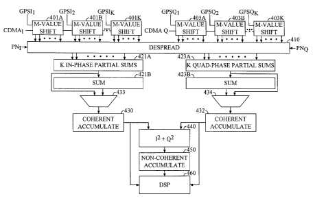
FIG. 5 depicts the searcher of FIG. 2 modified in accordance with the
present invention. Like numbered objects are identical in the two figures, and
the modifications will be detailed below.
10 N-value shift registers 400 and 402, from FIG. 2, have been replaced with
series of M-value shift registers 401A-K and 403A-K respectively. Each M
value shift register 401A-K and 403A-K has a selectable input which can be set
to select a GPS input (from among GPSh_K and GPSQ,_K respectively) or the
output of the prior M-value shift register (except for the initial registers,
401A
and 403A, which select the CDMA I and Q sequences, respectively).
When configured for CDMA pilot searching, as described above, each M-
value register is configured to select as its input the output of the prior M-
value
register (except for the initial registers, 401A and 403A, which select the
CDMA
I and Q sequences, respectively). In this mode, M-value shift registers 401A-K
and 403A-K function identically to the N-value shift registers, 400 and 402
respectively, that they replace.
When configured for GPS searching, each M-value shift register 401A-K
or 403A-K selects as its input the in-phase or quadrature component of the GPS
signal it is to decode, namely GPSI,_K and GPSQ,_K respectively. Those skilled
in
the art will recognize that a variety of configurations of the M-value
registers
are possible. For example, when K registers are available but only K/2 pilots
need to be searched, the K registers can be configured in pairs to form K/2 2M
valued registers. Implementors of this invention can choose the level of
independent programmability of the selectable inputs of M-value shift
registers
401A-K and 403A-K to suit their specific requirements.
The outputs of M-value shift register 401A-K and 403A-K are then
despread in despreader 410 in the fashion described above in reference to FIG.
3
and FIG. 4. The PN sequences for the despreading are chosen based upon
whether CDMA pilot searching or GPS pilot searching is required. The
appropriate codes are loaded into despreader 410. In FIG. 5, only a single in-
phase code (PNI) and a single quadrature phase code (PNQ) are shown as
inputs to despreader 410. This configuration requires the K GPS codes to be
concatenated and loaded serially. Those skilled in the art will know how to
CA 02393509 2002-06-04
WO 01/47135 PCT/US00/34774
11
provide additional taps to allow multiple sections of the despreader to be
loaded with GPS or CDMA codes, and this option is detailed below in reference
to FIG. 6D. (Keep in mind that CDMA and GPS pilot searching are the options
selected in the exemplary embodiment of this invention. Those skilled in the
art will recognize that this invention is readily usable for other situations
in
which a variable number of sources must be searched with a variable number of
different PN sequences.)
Summers 420 and 422 of FIG. 2 are replaced in FIG. 5 with partial
summers 421A and 423A followed by additional summers 421B and 423B.
Summer 421A computes K sums of the despread in-phase results and summer
423A computes K sums of despread quadrature phase results. These results are
the complete sums when the searcher is operating in GPS mode, and the results
are delivered to mux 433 and mux 434, respectively. When the searcher is
configured for CDMA pilot searching, the K sums represent partial sums, and
they must be summed in summers 421B and 4238, respectively. The results of
summers 421B and 423B are delivered to muxes 433 and 434.
Muxes 433 and 434 are used to select between the partial sums (which
represent complete sums for the K individual GPS pilots) and the complete sum
used for CDMA pilot searching. The results are delivered to coherent
accumulators 430 and 432 respectively. In CDMA mode, coherent accumulators
430 and 432 function as described above in reference to FIG. 2. Without
modification, only the memory element of the accumulators is useful during
GPS mode - the results must be delivered to a processor such as DSP 460, as
shown, for coherent accumulation. Another option is to construct coherent
accumulators 430 and 432 in a programmable fashion such that the integrated
adders (not shown) can be reconfigured to produce K accumulations when GPS
searching is being conducted. In either case, in the exemplary embodiment, the
results are delivered to DSP 460 for energy computation, non-coherent
accumulation, peak detection, and other processing necessary for pseudorange
generation. This is not mandatory, as hardware used for CDMA pilot detection
can be deployed to compute values for GPS detection as well. However, rather
than a single path, as is the case for CDMA, K paths would need to be
constructed to give the K desired results. This would require K times the
hardware or a factor K increase in processing speed (if the existing hardware
were time-shared).
The results from coherent accumulators 430 and 432 are delivered to
energy calculator 440, non-coherent accumulator 450, and then to DSP 460 for
processing in the fashion described in reference to FIG. 2 above.
CA 02393509 2002-06-04
WO 01/47135 PCT/US00/34774
12
FIGS. 6A-6D depict the exemplary embodiment of the present invention.
This embodiment is configured to support CDMA searching or simultaneous
search of eight GPS satellites with minimal impact or increase in hardware
required of the CDMA searcher described in the '010 application.
In FIG. 6A, received signals enter antenna 700 and RF processing tasks
such as amplification, down-conversion, filtering, and A/D conversion are
carried out in receiver 702. The results are delivered to optional matched
filter
704 and mux 706. Mux 706 selects the filtered or non-filtered version to be
processed by the eight GPS front ends, comprised of blocks 708A-G, 710A-G,
and 712A-G. Code doppler adjust blocks 708A-H receive the signal from mux
706. The resultant code doppler adjusted signals are processed in rotators
710A-H, respectively, to accommodate the independent frequency doppler
effects from the eight satellites. These resultant signals are decimated in
decimators 712A-H. Decimation is optional. In the exemplary embodiment, the
digital IQ samples coming from receiver 702 are sampled at chipx8, or eight
times the chip rate. The exemplary decimators 712A-H provide output signals
which can be at rates chipx8 (no decimation), chipx4, or chipx2. The outputs
of
decimators 712A-H are labeled PATH_1 through PATH 8, respecively.
FIG. 6B shows the exemplary code doppler adjust block. It is labeled as
code doppler adjust block 708A, but is representative of blocks 708A-H. IQ
data from mux 706 enters and is delivered to tap delay line 716A, which has
eight taps in the exemplary embodiment. The IQ data also goes to optional
interpolating filter 714A. The output of interpolating filter 714A is
delivered to
tap delay line 718A, also containing 8 taps in the exemplary embodiment. Each
output of tap delay lines 716A and 718A is selectably controlled by a DSP (DSP
820 in FIG. 6C). Mux 720A selects one output of either tap delay line 716A or
716B, and delivers the output to rotator 710A, as described above.
In FIG. 6C, signals PATH 2 through PATH 8 are shown entering muxes
802B-H, respectively. These muxes are used to switch the input to tap delay
lines (TDL) 800B-H between signals PATH 2 through PATH 8 and the output
of the prior TDL, 800A-G, respectively. PATH_1 feeds directly into TDL SOOA.
Those skilled in the art will recognize the option to program the entire path
from antenna 700 through to PATH_1 such that it represents the CDMA pilot
search data or data for one of the eight GPS search pilots. Each of TDL 800A-H
is of length 16 with 8 taps. This allows for computation on half-chip
boundaries. The results of each of TDL 800A-H are directed to QPSK
despreaders 804A-H, where despreading occurs with either the PN sequence
CA 02393509 2002-06-04
WO 01/47135 PCT/US00/34774
13
for CDMA pilot searching, labeled CDMA_PN, or one of the GPS coarse
acquisition sequences CA 1 A through CA 8 A.
As an alternative, as shown in relation to despreader 410 in FIG. 5, the
codes CA_1 A through CA 8 A can be sequenced onto the single chained
input to despreaders 804A-H as shown through input CDMA_PN. In the
exemplary embodiment, as shown in FIG. 6C, each of sequences CA_1 A
through CA 8 A feeds directly into despreaders 804A-H, respectively. The
generation of these sequences is shown in FIG. 6D. Separate gold code
generators for each channel (not shown) produce sequences CA_1 through
CA 8, which feed into TDLs 830A-H. Each of these TDLs is of length 24 with
taps at positions 0,4,8,16, and 24. The outputs of these taps are selected at
rate
chipx8 by muxes 832A-H to produce signals CA_1 A through CA 8 A. This
allows each GPS channel to search up to four adjacent windows spanning 16
chipx2 hypotheses in every eight-chip interval during a coarse search. Mux 834
is used to concatenate these sequences for delivery to QPSK despreader 804A
through input CDMA_PN.
The despread results are delivered to summers 804A-H to produce the
values labeled GPS sum_1 through GPS sum 8. These values are available for
accumulation in coherent accumulator 810. In CDMA mode, these values
represent partial sums and must be summed in summer 808. The resultant
signal is labeled CDMA. The CDMA signal can be rotated in rotator 812 (this
block is optional) and the result is also available to coherent accumulator
810.
Coherent accumulator selects between the GPS sums or the CDMA value
depending on the current operational mode. The results of the coherent
accumulation are delivered to DSP 820 during GPS searching. During CDMA
searching, the results of coherent accumulation are delivered to energy
calculator 814. Those results are passed on to non-coherent accumulator 816,
and those outputs are delivered to DSP 820. (Note that other hardware
processing may take place after non-coherent accumulation rather than in the
DSP, as discussed in the '010 application.)
Thus, a method and apparatus for a programmable matched filter
searcher for multiple pilot searching has been described. The description is
provided to enable any person skilled in the art to make or use the present
invention. The various modifications to these embodiments will be readily
apparent to those skilled in the art, and the generic principles defined
herein
may be applied to other embodiments without the use of the inventive faculty.
Thus, the present invention is not intended to be limited to the embodiments
CA 02393509 2002-06-04
WO 01/47135 PCT/US00/34774
14
shown herein but is to be accorded the widest scope consistent with the
principles and novel features disclosed herein.
WE CLAIM: