Note: Descriptions are shown in the official language in which they were submitted.
CA 02393536 2002-06-03
METHOD FOR ORGANIZING A PRODUCTION LINE AND METHOD
AND APPARATUS FOR ASSEMBLING A VEHICLE BODY
BACKGROUND OF THE INVENTION
Field of the Invention
The present invention relates to a method for organizing a production line,
for
example, a method for organizing a production line capable of producing a
plurality of
types of vehicles by a single production line, and in particular, relates to a
method for
organizing a production line capable of providing efficient production by
absorbing
differences in manhour due to the type of vehicles and to a vehicle body
assembly
method and a vehicle body assembly line, capable of reducing the length of the
single
line and exhibiting a high productivity. ,
Background Art
A conventional design concept for organizing the flow production system of,
for .
example, vehicles is disclosed in Japanese Unexamined Patent Application,
First
Publication No. Sho 61-21870, in which two assembly lines including a main
line for
integrating main parts and a sub-line for integrating subparts are
constructed.
A production line design for producing a plurality of types of vehicle mixed
on a
single line is disclosed in Japanese Patent (Granted) Publication No. 2920801.
The
concept of the above patent is known as a production line whose assembly speed
is
changed suitably for producing a plurality of vehicle types on a single line
with a
favorable production efficiency.
CA 02393536 2002-06-03
2
As described above, a plurality of types of vehicle bodies are usually
assembled
by two production lines. In most cases, these two lines include the main line
for
assembling the main components and a subsidiary line for supplying the
components
collectively to the main line after assembling the parts into the sub-
assembled
components.
For example, car bodies, conveyed to an assembly line after the coating
process,
are assembled while passing through the main line, which comprises an
installation line,
an underside assembly line and so on. In assembling the car body in the main
line, the
sub-assembled components, which are sub-assembled in the sub-assembly line
connected to the main line, are supplied to the main line.
In conventional production lines, it is inevitably necessary to design the
production line to be able to produce the type of vehicle having the largest
number of
parts, when taking various factors such as forms of production, equipment,
specifications,
and the number of parts into consideration. Thus, the length of the main line
increases,
which results in increasing the redundant manhours and unnecessary utility
expenses,
and increasing the production cost.
That is, in order to produce a plurality of types of vehicles having digerent
numbers of parts on the same line, the manhours required for one particular
type of
vehicle differ from those for other vehicles. Accordingly, when a type of
vehicle
having a small number of parts is conveyed on the main line, some of the
manpower
available for another type of vehicle having a larger number of parts becomes
redundant.
One of the purposes of the present invention is to provide a method of
organizing
a production line, capable of producing a plurality of types of vehicles
efficiently while
absorbing differences in manhour due to the vehicle type.
Recently, the production of vehicles has changed from large scale production
of a
CA 02393536 2002-06-03
3
few types of vehicles to the small scale production of multiple types of
vehicles, it has .
been a general trend to produce multiple types of vehicles on the same
production line in
response to diversified consumer demands. Accordingly, there has been a
tendency for
the production lines to become longer.
That is, considering the assembly forms, equipment, specifications, and the
number of parts or components to be assembled, each of which differs for each
vehicle
type, the length of a production line for producing multiple types of vehicles
must be
determined based on the type of vehicle using the largest number of parts.
Therefore,
the length of the production line for producing a multiple types of vehicles
inevitably
becomes long, which results in increasing the supplementary facilities,
substantially
reducing the productivity, and increasing the costs.
Furthermore, since a variety of vehicles comprising different numbers of parts
and
components are assembled on the same line, the number of manhours varies
according to
the type of vehicle. When a type of vehicle having a small number of parts is
conveyed,
the operators required for assembling a type of vehicle comprising a larger
number of
parts become redundant, and the productivity is reduced. Consequently, this
redundant
labor causes a reduction of the productivity and an increase of the cost.
SUMMARY OF THE INVENTION
It is therefore an object of the present invention to provide a production
line
organizing method, a vehicle assembling method, and a vehicle assembly line,
capable
of reducing the length of the main assembly line and of improving the
productivity.
In order to solve the above problem, the first aspect of the present invention
is to
provide an assembly line organizing method, capable of producing a plurality
of types of
vehicles on a single line, comprising the steps of classifying all vehicle
parts into main
CA 02393536 2002-06-03
4
parts and subparts by classifying parts which are common to all types of
vehicles as
main parts and classifying remaining parts other than the main parts as
subparts,
classifying all subparts into synchronizing subparts and non-synchronizing
subparts by
classifying subparts which can be assembled in synchronous with the assembly
in the
main line as synchronizing subparts and classifying other remaining subparts
as
non-synchronizing subparts, and allocating all integrating and assembly
manhours of the
non-synchronizing subparts classified in the above subparts classification
step to at least
either the difference in manhours for the assembly of the main parts depending
on the
vehicle type or the difference in manhours for the assembly of the
synchronizing
subparts depending on the vehicle type.
By forming the above constitution, redundant manhours generated by the
difference in manhoufs for the assembly of the main parts depending on vehicle
type or
the difference in manhours for the assembly of the subparts depending on the
vehicle
type can be assigned to the manhour for the assembly of non-synchronizing
subparts.
According to the second aspect of the present invention, in the above
production
line organizing method, all integrating and assembly manhour of said non-
synchronizing
subparts are abridged and a new assembly manhour is defined by this abridged
manhours on the assumption that non synchronizing subparts can be assembled in
a
more efficient manner by abridging the assembly, and the production line
organizing
method comprises the steps of allocating the new assembly manhour to either
the
manhour difference of the main parts due to the vehicle type or the manhour
difference
of the synchronizing subparts due to the vehicle type.
By forming the above constitution, the new integrating and assembly manhours
of
all non-synchronizing subparts are defined by collecting and abridging into
more
efficient assembly manhours, and the new assembly manhours can be assigned to
either
CA 02393536 2002-06-03
the difference of manhours in assembly of the main parts due to the vehicle
type or the
difference of manhours in assembling the synchronizing subparts due to the
vehicle type.
The third aspect of the present invention is to provide an assembly method of
a
plurality of vehicle bodies by assembling main parts and subparts (for
example, a set of
5 subparts B in the embodiment) for a vehicle body (for example, vehicle body
2 in the
embodiment) while conveying the vehicle bodies after coating comprising the
steps of:
assembling in a main process first main parts (for example, main part MB l ),
which are
common to all types of vehicle bodies, and, among main parts (for example,
main parts
MB in the embodiment) which are not common to all types of vehicles, second
main
parts (for example, main parts MB 2), which are not common to all types of
vehicles but
whose assembly can be accommodated while absorbing a differences in assembly
manhours due the vehicle type; and assembling in a subprocess third main parts
(for
example, third main parts in the embodiment), which are not common to all
types of
vehicles and whose assembly cannot be accommodated by absorbing the difference
in
manhours due to the vehicle type, as a unit of parts; supplying to the main
process after
assembly first subparts (for example, subparts SB 1 in the embodiment), which
can be
assembled synchronously with the main line, after assembly in a sub-main
process;
storing after subassembly by a non-synchronous process subparts (for example,
subparts
SB2 in th embodiment) which cannot be assembled synchronously with the main
line,
and said third main parts, whose assembly cannot be accommodated by absorbing
differences due to the vehicle type; and supplying said sub-assembled parts to
the
sub-main process and to the main process.
By the above constitution, the changes in the assembly manhours for different
vehicle types can be absorbed in the subprocess without affecting the
production flow in
the main process. In the subprocess , the subparts, which can be common to all
vehicle
CA 02393536 2002-06-03
6
types, are assembled synchronously with the main process, and the subparts
which
cannot assembled synchronously and the subassembled main parts whose assembly
cannot be accommodated within the main process are stocked for supplying to
the main
process and the sub-main process.
The differences due to the vehicle type of the second main parts, whose
assembly
can be accommodated with the main line, are absorbed in various ways such as
use of
the assembly jigs, improvement of the assembly operation, and adoption of an
automated
systems and unification of the specifications.
By the above constitution, the time for assembling the second main parts MB2
whose assembly can be accommodated by absorbing the difference in manhours due
to
the vehicle type is shortened by considering the assembly forms, equipment and
specifications, that is, by the use of the assembly jigs, improvements in the
assembly
operation, reduction of man-hours by adoption of automated systems, and
unification of
the specifications, it is possible to quickly bring the operator to a high
level of skill and
to increase the productivity.
The other aspect of the present invention provides an assembly line of a
plurality
of types of vehicle bodies after coating for assembling main parts and
subparts while
conveying the vehicle bodies comprising: a main line for assembling first main
parts,
which are common to all types of vehicle bodies, and second main parts, which
are not
common to all vehicle types but can be assembled while absorbing differences
in
manhours in the assembly operation due to the vehicle type; a sub-line for
unitizing and
assembling the third main parts, which are not common to all types of vehicles
and
which cannot absorb the differences in manhours due to the vehicle type;
wherein the
sub-line comprises a sub-main line, connected to the main line for supplying
first
subparts, which can be assembled synchronously with the main line, after
assembly in a
CA 02393536 2002-06-03
sub-main line; a non-synchronous part manufacturing area, in which subparts
which
cannot be assembled synchronously with the main line and main parts which
cannot be
assembled while absorbing the differences in manhours due to the vehicle type;
and a
storage area which stores subparts assembled in the non-synchronous part
manufacturing
area and main parts, which cannot absorb the differences in manhours due to
the vehicle
type, and supplies these parts in the storage area to the sub-main line or to
the main line.
By the above constitution, the main parts, which are common to all vehicle
types
and the main parts which are not common to all vehicle types but can be
assembled by
absorbing the differences in manhours due to the vehicle type are assembled in
the main
line. The main parts, which are not common to all vehicle types and which
cannot
absorb the differences in manhours due to the vehicle types, and the subparts
are
assembled in the sub-line, wherein the main parts, which can be assembled
synchronously with the main line, are assembled in the sub-main line and are
supplied to
the main line. In addition, the subparts which cannot be assembled
synchronously with
the main line and the main parts whose assembly cannot be accommodated because
of
the differences in manhours due to the vehicle types are stocked in the
storage area and
they are supplied to the main line or the sub-main line when necessary.
BRIEF DESCRIPTION OF THE DRAWINGS
Fig. 1 is a diagram showing a view of the entire vehicle body assembly line
organized according to one embodiment of the present invention.
Fig. 2 is a diagram explaining the relationship between the parts and the
vehicle
types in one zone.
Fig. 3 is a flowchart showing a procedure for organizing the production line
according to one embodiment of the present invention.
CA 02393536 2002-06-03
8
Fig. 4 is a graph showing the manhours required for assembly of various types
of
vehicles in one zone.
Fig. 5 is a graph showing the manhours required for assembly of subparts for
various types of vehicles at a zone.
Fig. 6 is a graph showing the collected state of the non-synchronizing
subparts
among the subparts in one zone.
Fig. 7 is a graph showing the manhours required for the main parts at a zone
Fig. 8 is a graph showing the abridged result of the assembly manhours of the
non-synchronizing subparts.
Fig. 9 is a schematic block diagram showing the structure of devices for
organizing the production line according to one embodiment of the present
invention.
Fig. 10 is a diagram explaining the main line according to an embodiment of
the
present invention.
Fig. 11 is a diagram of the main line shown in Fig. 1 explaining the
differences in
the numbers of parts for a few types of vehicles.
Fig. 12 is a diagram explaining whether each part is used for each type of
vehicles.
Fig. 13 is a diagram showing how each part is classified as a main part or a
sub-part.
Fig. 14 is a diagram explaining the line layout of the assembly line according
to
one embodiment of the present invention.
DETAILED DESCRIPTION OF THE INVENTION
Hereinafter, an embodiment of the present invention is described with
reference to
the attached drawings.
The constitution of the assembly line and parts to be assembled are explained
CA 02393536 2002-06-03
9
referring to an example of the assembly line for assembling vehicle bodies.
Fig. 1 is a diagram showing the entire view of the vehicle body assembly line
organized according to one embodiment of the present invention. In Fig. l,
reference
numeral 1 denotes a main line, which is used for assembling various parts for
a plurality
of types of vehicle bodies 2 (product) supplied after being coated in the
coating process.
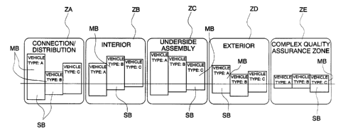
This main line 1 in practice comprises a connection/distribution zone ZA, an
interior zone ZB, a underside assembly zone ZC, an exterior zone ZD, and an
complex
quality assurance zone ZE. The vehicle body after being assembled in the main
line 1
is transferred to the subsequent process for inspection. The main line 1
therefore
corresponds to the main process. Here, it is noted that three inspection
sections ZX are
provided after respective zones ZA, ZB, and ZC in addition to the complex
quality
assurance zone ZE.
Various supply lines are connected to the connection/distribution zone ZA such
as
a fuel/brake unified pipe assembly sub-line 3, an air-conditioner condenser
unit supply
line 4, an ABS modulator assembly sub-line 5, and a radiator assembly sub-line
6, in
order to respectively install a fuel/brake unified pipe assembly, an air-
conditioner
condenser unit, an ABS modulator assembly, and a radiator assembly. These sub-
lines
are operated while moving synchronously with the main line 1.
Various supply lines are also connected to the interior zone ZB such as a roof
lining unit sub-line 7, a fuse unit box sub-line 8, an air-conditioner unit
sub-line 9, a
headlight unit sub-line 10, and a switchboard panel unit assembly sub-line 11;
a bumper
assembly conveyer sub-line 12, in order to respectively install a roof lining
unit, a fuse
unit box, an air-conditioning unit, a head light unit, a switchboard panel
with soft lining
assembled on a conveyer, and a bumper assembled on a conveyer. The
above-described sub-lines are operated while moving synchronously with the
main line
CA 02393536 2002-06-03
1. Here, a control box sub-line 13, which moves non-synchronously with the
main line
I, is connected to the above-described switchboard panel unit assembly
conveyer line 11.
It is noted that control boxes for all types of vehicles are assembled in this
control box
sub-line 13.
5 Various sub-lines are connected to the underside assembly zone ZC such as a
rear
suspension subassembly conveyer sub-line 14, a front suspension assembly
subassembly
conveyer sub-line 15, a fuel tank unit sub-line 16, and an exhaust pipe
assembly
subassembly sub-line 17, in order to install a rear suspension sub-assembled
into
subassembly on a conveyer, a front suspension sub-assembled into subassembly
on a
10 conveyer, a fuel tank unit, and a exhaust pipe assembly subassembly.
Here, a rear suspension assembly subassembly sub-sub-line 18 is connected to
the
rear suspension subassembly conveyer sub-line 14, and a dressed engine
subassembly
sub-sub-line 19 is connected to the front suspension assembly subassembly
conveyer
sub-line 1 S. It is noted that the dressed engine subassembly means an
assembly of an
engine and a transmission.
The above-described rear suspension assembly subassembly sub-line 18 assembles
rear suspension assemblies for all types of vehicles non-synchronously with
the main
line 1 for supplying them to the above-described rear suspension small
assembly
conveyer sub-line 14. The dressed engine subassembly sub-sub-line 19 assembles
all
vehicle types of dressed engines non-synchronously with the main line 1 for
supplying
them to the above-described front suspension subassembly conveyer sub-line 15.
Various sub-lines such as seat assembly sub-lines 20 and 21 and glass assembly
sub-lines 22 and 23 are connected to the exterior zone ZD, in order to install
the front
and rear seat assemblies and the front and rear glass assemblies. These sub-
lines are
synchronous with the main line 1.
CA 02393536 2002-06-03
11
Finally, in the complex assurance zone ZE, various operations are carried out
such
as a coolant filling operation, mounting of the battery, a fuel filling
operation, and
confirmation of the engine start.
In addition, in the exterior zone ZD, a front door assembly, a rear door
assembly,
and a tail gate assembly are installed, which are removed in the
connection/distribution
zone ZA and assembled in the door and tail gate assembly lines 24. It is noted
that
there are other sub-sub-lines which are not shown in Fig. 1, in addition to
the main line l,
sub-lines 3 to 12, 14 to 17, and 20 to 23, and sub-lines 13, 19, and 18.
The above-described zones are classified by the fimctions of the assembly
operations, and an object of the functional classification of the operations
is to make it
possible to prevent disassembly and reassembly operations by executing quality
assurance at each inspection section ZX provided after each assembly zone from
ZA to
ZD. For example, both ends of a trunk grid switch cable are fixedly connected
in the
connection/distribution zone ZA. However, since the action of a trunk grid
switch
cable is confirmed by inspecting the working function of the cable in the
inspection
section ZX after the connectionldistribution zone ZA, it is possible to
eliminate to
eliminate a disassembly processes of the assembled body formed in the zone ZA
in the
following zone for fixing errors.
Concretely speaking, in the conventional production line, one operator in
charge
of an operation carnes out the operation such that, for example, when one
operator
attaches the fibnt end of the cable and the other operator attaches the back
end of the
cable, if the first operator attaches the front end without providing slack,
this defective
attachment may go unnoticed until it is found by another operator and,
reassembly may
be required when it is found. However, since an inspection section is provided
after
each assembly zone in the present assembly line, the assembly operations
executed in
CA 02393536 2002-06-03
12
one assembly zone can be completed in that assembly zone without generating
defects in
later assembly zones.
When two types of vehicle bodies 2 are conveyed to an assembly zone, a
difference arises in the manhours for assembly and the number of parts by the
types of
vehicles as shown in Fig. 2.
Practically speaking, the vehicle type D comprises eight parts from No. 1 to
No. 8.
However, the vehicle type A comprises five parts not including No. 2, No. 4
and No. 7,
and the vehicle B comprises five parts not including No. 1, No. 6 and No. 7.
Furthermore, the vehicle type C does not include No. 1, No. 4 and No. 7, and
the vehicle
type E does not include No. 2 and No. 7. The number of parts differs by the
vehicle
type due to differences in equipment.
In the present zone, the parts No. 3, No. 5, and No. 8 are common to all
vehicle
types from A to E, but the other parts No. 1, No. 2, No. 4, No. 6, and No. 7
are not
common to the vehicle types from A to E.
Similar to the present zone, there are the common parts and non common parts
in
other respective zones. Accordingly, if the assembly line is organized so as
to be able
to produce a vehicle type having the greatest number of parts, an assembly
operation of a
vehicle having the small number of parts will generate redundant operators.
Now, a production line organizing method of the present invention will be
described below with reference to the flowchart shown in Fig. 3, and Figs. 4
to 8.
As shown in Fig. 3, in any zone, common parts common to all vehicle types are
classified as main part MB (step S 1 ), and other parts are classified as
subparts SB (step
S2). A main and subparts classification process is constituted by the step S 1
and step
S2. Concretely, as shown by the bar graph in Fig. 4, the parts are classified
into the
common parts common to all vehicle types A to E and subparts not common to all
CA 02393536 2002-06-03
13
vehicle types A to E. In the example shown in Fig. 2, the parts No. 3, No. 5
and No. 8
are classified as the main parts, and parts No. 1, No. 2, No. 4, No. 6 and no.
7 are
classified as the subparts.
The dashed lines in Fig. 4 illustrate the number of subparts SB classified for
respective vehicles in the subpart side. As shown in the figure, the number of
the main
parts MB differs by types of vehicles, so that the manhours required for
assembly of the
main parts varies depending on the vehicle type. The hatching in Fig. 7 shows
the
differences of assembly manhours depending on the vehicle type.
Subsequently, in step S3 shown in Fig. 3, subparts that can be assembled
synchronously with the main line are classified as synchronous subparts SB1,
and in
subsequent step S4, the remaining subparts, other than the synchronous
subparts, are
classified as the non-synchronous subparts SB2. The combination of step S3 and
step
S4 constitutes the classification process to classify subparts into
synchronous subparts
and non-synchronous subparts.
Practically speaking, as shown in Fig. 5, which is a bar graph of the manhours
required for assembling subparts, subparts should be divided into two groups,
in which
one includes synchronous subparts SB1 which can be assembled in synchronism
with
the main parts, and another includes non-synchronous subparts which cannot be
assembled in synchronism with the main parts. The number of synchronous
subparts
SB 1 differs depending on the vehicle type so that the manhours for the
assembly of the
synchronous subparts SB 1 is not always the same and varies depending on the
vehicle
type. The hatching lines in Fig. S show the differences of manhours due to the
vehicle
type.
In step S55 shown in Fig. 3, the non-synchronous subparts SB2 are collected as
a
group of subparts irrespective of the vehicle type as a block of new non-
synchronous
CA 02393536 2002-06-03
14
subparts SB3 (non-synchronous subparts collection process). In practice, the
manhours
for assembling the subparts of respective vehicles are shown in Fig. 6 as a
bar graph (the
longitudinal axis is operating hours as manhours), and the manhours for
non-synchronous subparts SB2 are collected, independently of the vehicle type,
as a
block of non-synchronous subparts SB3 as shown below the horizontal borderline
of Fig.
6.
Subsequently, in step S6 in Fig. 3, the total manhours for the collected
non-synchronous subparts SB3 for all types of vehicles are abridged for
obtaining new
total manhours for all non-synchronous subparts SB3. These new total manhours
are
allocated to the manhour differences due to the change of the assembly
manhours of the
main parts MB depending on the vehicle type in the main line 1 and to the
manhour
differences due to the change of the assembly manhours of the synchronous
subparts
SB 1 depending on the vehicle type in the sub-line 1 and the flow is
completed.
It is noted, however, that when the total manhours for the non-synchronous
subparts SB2 are not so large and the above total manhours for the non-
synchronous
subparts SB2 can be simply allocated to the differences in manhours of the
main parts or
the synchronous subparts, it is not necessary to allocate the above-described
total
manhour to both differences in assembly manhours of the main parts and
synchronous
subparts. The non-synchronous subparts allocation process is constituted by
this step S6.
Practically, the total manhours for the assembly of the new non-synchronous
subparts SB3 are allocated to either the manhour deviation Rlof the
synchronous
subparts SBl due to the difference of the vehicle types, shown in Fig. 6 by
hatching lines
or the manhour deviation R2 of the main parts MB due to the difference in the
vehicle
types, shown in Fig. 7 by hatching lines.
Here, the total assembly manhours of the non-synchronous subparts SB2 are
CA 02393536 2002-06-03
abridged as shown in Fig. 5 and the total assembly manhours are updated to the
new
total assembly manhours of the non-synchronous subparts SB3 as shown in Fig.
6, and
Fig. 8 shows how to allocate the new total assembly manhours for the non-
synchronous
subparts SB3 to the manhour deviation R2 of the main parts MB due to the
difference of
5 the vehicle types and the manhour deviation R1 of the synchronous subparts
SB 1 due to
the difference of the vehicle types. The non-synchronous subparts SB2 in Fig.
8 show
manhours for the non-synchronous subparts for the vehicles from A to E, shown
in
Fig. 5
According to the present invention, since the assembly manhours for the
10 non-synchronous subparts SB2 are abridge and updated the manhours for the
new
non-synchronous subparts SB3, it becomes possible to organize a more
productive and
efficient production line. It is noted that the manhours of the non-
synchronous
subparts SB3 can be further assigned as the manhour for the non-synchronous
subparts
in addition to the manhour differences ERl and ER2.
15 In the thus organized production line, redundant labor force created by the
manhour differences ER2 of the main parts MB due to differences in the vehicle
types
and the differences in assembly manhour differences ERl of the synchronous
subparts
SB 1 depending on the vehicle types can be allocated to the assembly operation
of the
non-synchronous subparts SB2.
That is, some of the operators who are engaged in assembly operations by the
main line and the sub-line for one type of vehicles, whose part number is
large, become
redundant when other types of vehicle, whose parts number is small, are
transported on
the main line and the sub-lines. That is, the operators become redundant in
the main
line for the assembly of the main parts, as shown in Fig. 7 and also in the
sub-line for the
assembly of the subparts SBI, as shown in Fig. 6. However, in the new
production line,
CA 02393536 2002-06-03
16
these redundant operators can be allocated to the new non-synchronous subparts
SB3,
which is obtained by collecting the non-synchronous subparts and by abridging
the
collected assembly manhours, so that the new production line does not generate
a
redundancy of operators.
In a practical process, for example, in the underside assembly zone ZC, when
the
vehicle body, whose part number is small, i transported on the assembly line,
since the
assembly manhours are relatively short, redundancy of operators occurs mainly
in the
rear suspension subassembly conveyer sub-line 14 or in the front suspension
assembly
subassembly conveyer sub-line 15. However, these operators can be assigned to
the
assembly operations of the non-synchronous parts in the rear suspension
assembly
subassembly sub-line 18 or the dressed engine subassembly sub-sub-line 19,
which
results in eliminating redundancy of manhours.
Accordingly, the production line of the present invention is not only capable
of
reducing the number of operators when compared with the case of arranging
operators in
every zones when providing for the vehicle type having the largest number of
parts, but
is also capable of providing more uniform workload to the operator. It is
noted that the
design concept of the present invention is highly flexible with respect to
increases in the
number of vehicle types, although .it takes more manhours for classifying the
common
parts of an increased number of vehicle types.
As a result, the present invention makes it possible to design an efficient
production line with a reduced length, which realizes mixed production of a
plurality of
vehicle types by absorbing differences in production manhours due to vehicle
types, and
which results in increasing the practical production capacity and reducing the
production
costs.
Next, an apparatus for organizing the above-described production line is
described
CA 02393536 2002-06-03
17
with reference to Fig. 9.
As shown in Fig. 9, this apparatus is provided with a control circuit 100 for
storing
the flowchart shown in Fig. 3, and an input device 101 for inputting data to
the control
circuit 100 and a display device 102 for displaying the data output from the
control
circuit 100 are connected to the control circuit 100.
The data regarding the parts for each type of vehicle is input by said input
device
101. The data to be input includes the manhours required for assemhling the
parts, the
components for assembling the part, and the assembly zone for the parts to be
handled.
When the data is input, the control circuit 100 forms the map of these parts
in the form
shown in Fig. 2.
Next, when the vehicle type to be assembled in the main line 1 is selected by
the
input device 141, the control circuit 100 conducts classifying operations in
sequence for
classifying the main parts (step S 1 ), the subparts (step S2), the
synchronizing subparts
(step S3), the non-synchronous subparts (step S4), abridgement of the non-
synchronous
subparts (step SS) and assignment of the non-synchronous subparts (step S6)
according
to the flowchart shown in the above-described Fig. 3.
The result obtained by the above procedure is displayed on the display device
102,
and the operators to be assigned to the non-synchronous subparts are selected.
It is noted that this invention is not limited to the above-described
embodiment,
and the present invention can be applied not only to the production line for
vehicles but
also, for example, to production lines of various products such as electrical
products.
Fig. 10 is a diagram explaining a main line according to an embodiment of the
present invention. Fig. 11 is a diagram of the main line in Fig. 10 showing
the
differences in the number of parts for a few types of vehicles. In Figs. 10
and 11,
reference numeral 1 denotes the main line, which is used for assembling
various parts in
CA 02393536 2002-06-03
18
sequence for a few types of the vehicle bodies 2 conveyed after being coated
in the
coating process. This main line practically comprises a
connection/distribution zone
ZA, an interior zone ZB, a underside assembly zone ZC, an exterior zone ZD,
and an
complex quality assurance zone ZE. The vehicle body after being assembled in
the
main line 1 is transferred to the subsequent process for inspection. The main
line 1
therefore corresponds to the main process.
Here, assembly operations conducted in the connection/distribution zone ZA
include, for example, wiring, piping, and wire distribution, operations in the
engine
compartment, and other pre-assembly operations, and assembly operations in the
interior
zone ZB include installation of instrument panels, pedals, floor mats, ceiling
lining, side
linings etc. Assembly operations in the underside assembly zone ZC include
assembly
of the suspension and the engine, and operations in the exterior zone ZD
include
installation of tires, the windshields, bumpers, doors, seats, post operations
of the engine
room and other exterior operations, and operations in the complex quality
assurance
zone ZE include a coolant filling operation, mounting of the battery, a fuel
filling
operation, and confirmation of the engine start.
The above-described zones are defined by classifying the functions of the
respective operations. Although those operations are conventionally carried
out step by
step by an operator in charge of the operation, the classification of the
operations by
their functions and the assurance of functions of those operation for each
zone makes it
possible to eliminate subsequently disassembling and reassembling of the
vehicle. For
example, since in the connection/distribution zone the action of the trunk
grid switch
cable is confirmed by inspecting its operation, it is possible to eliminate
the disassembly
the assembling in the following zone for repair purposes.
Conventionally, when one operator in charge of a process carries out one
process,
CA 02393536 2002-06-03
19
that is, for example, when one operator attaches the front end of the cable
and another
operator attaches the back end of the cable, if the first operator attaches
the front end
without providing slack, this defective attachment may go unnoticed until it
is found by
another operator and, reassembly may be required when it is found.
The bar graph for each type of vehicle shown in Fig. 13 illustrates the number
of
parts, and the part of the bar graph upward above the horizontal line shows
the number
of the main parts MB, and the part of the bar graph below the horizontal line
shows the
number of subparts SB. The main parts MB include parts suitable for all types
of
vehicles, parts whose correct functions are guaranteed in the sub-line, parts
to be
mounted directly onto the vehicle body, parts which cannot be assembled as a
unit, and
parts which qualified for the main line. In contrast, the subparts SB includes
parts
which differ due to the equipment, specifications and the structure of
vehicles, parts not
directly attached to the vehicle body, parts which can be assembled into a
unit, parts
which are difficult to attach from a favorable position, parts for which the
required
manhours can be reduced when they are defined as the subparts, and parts which
can be
automatically assembled or assembled using jigs when they are defined as
subparts.
Now, when the second type of vehicle body 2 is conveyed to each zone, the
necessary number of parts for the second vehicle body 2 differs from that used
for the
first type of vehicle body 1, as shown in Fig. 12. As shown in Fig. 12, the
number of
parts and the manhours required in the underside assembly zone ZC differ
depending on
the type of vehicle.
Practically, although the type A of vehicle uses main parts from No. 1 to No.
8, the
type B vehicle does not use parts No. 2 and No. 7. The parts for one type of
vehicle
differ from the parts for the other type of vehicle because of the difference
in
equipment for each vehicle type. Furthermore, the type C vehicle does not use
parts
CA 02393536 2002-06-03
No. 1, No.4, and No. 6.
That is, the first main parts MB 1 first assembled in the underside assembly
zone
ZC are main parts No. 3, No. 5, and No. 8, which are common to all types of
vehicles
including type A, type B, and type C. Examples of those main parts are the
suspension
5 and the fuel tank.
The second main parts subsequently used in the underside assembly zone ZC can
be classified into two types, one of which is the main parts MB 2, which can
absorb the
differences in assembly manhours due to the differences in the vehicle types,
and
another one of which is the main parts MB 3, which cannot absorb the
differences in
10 manhours in the assembly operation due to the differences in the vehicle
types (these
parts MB3 are unitized and assembled in the sub-line). The main parts MB 2 and
MB 3
correspond to the remaining main parts No. 1, No. 2, No. 4, No. 6, and No. 7,
which are
not common to all types of vehicles.
As shown in the vehicle type A in Fig. 13, the main parts defined as MB 2,
which
15 can absorb the differences in the manhour due to the difference in the
vehicle type,
include the main parts MB 21, which can absorb the difference in manhour of
the
assembly operation due to the differences in the vehicle type by adopting an
automatic
assembly process or by being assembled later, and the main parts MB22 whose
difference in manhours can be absorbed by using jigs; by unifying the
specifications, or
20 by improving the assembly operation. Practically, automated assembly
systems reduce
the manhours by automation, the use of jigs reduces the manhours required in
the
assembly operation, and the unification of the specifications eliminates the
differences
based on the differences in the type of vehicle, and the improvement of the
assembly
operation means to reduce the manhours in the assembly operation by modifying,
for
example, an operator's positioning in the assembly operation. The improved
assembly
CA 02393536 2002-06-03
21
operations shown above makes it possible to assemble those parts MB 21 and MB
22 in
the main assembly line. Practically, those parts MB21 and MB 22 assembled in
the
underside assembly zone ZC are, for example, a rear suspension mount and a
spare-tire
carrier.
The parts MB 3, whose differences in manhours in the assembly operation cannot
be absorbed, are first assembled in a non-synchronous part mounting area in
the sub-line
and then supplied to the main line. A practical example of this type of part
is a brake
sub-assembly supplied to an underside assembly zone ZC.
Fig. 14 illustrates the detailed layout around tl~e underside assembly zone ZC
to
which a sub-line for assembling a rear suspension RR is connected.
As depicted in Fig. 14, the sub-lines are connected to the main line 1. In the
sub-line, since it is possible to supply subparts B 1 from the sub-main line
in the sub-line
after assembling them in the sub-main line 3, the subpartsB 1 can be supplied
to the main
line without disturbing the Ilow of the main line.
In contrast, the subparts B2, which are non-synchronous with the main line 1,
and
the main part MB 3, which cannot absorb the differences in assembly manhours
depending upon the vehicle type and which are sub-assembled with the sub-parts
for
absorbing the difference in the man-hour due to the vehicle type, are
assembled in the
non-synchronous part mounting area 4 and stored in the storage area S, and are
supplied
to the main line from the storage area when necessary. The storage area
functions as an
area capable of absorbing the vehicle-type differences. Accordingly, if the
number of
vehicle types to be supplied to the main line 1 increases, the main line can
cope with an
increase of the vehicle types without extending the main line.
When two types of vehicle bodies are conveyed by the same main line 1, the
operators of the main line 1 engage in assembling the main parts common to
both
CA 02393536 2002-06-03
22
vehicles, so that there are no redundant operators, which results in
substantially
increasing the productivity. Furthermore, since the operation of the main line
for an
operator becomes a constant operation irrespective of the differences in the
type of
vehicle, the operators' skill will reach a high level within a short period,
which results in
reducing the assembly period and reducing the training period of the operation
for each
operator.
In the above-described non-synchronous part mounting area 4, since it is
possible
for the subparts SB to be assembled without synchronizing with the main line
1, an
operator, who cannot be engaged in the operations of the main line 1, can be
appointed
as the operator for the non-synchronous part mounting area 4, so that the load
on each
operator can be equalized, and personnel can be efficiently distributed
depending on the
capacity of each operator.
In assembling the main parts MB2, which can absorb the difference in manhours
in
assembly, and which are assembled on the main line 1, since the manhours for
assembly
can be reduced in various ways, such as using an assembly jig, adopting an
improved
operational method, adopting an automated assembly system, and unifying the
specifications of vehicles, it is possible to eliminate the loss due to a
change of the
vehicle type in the main line and to increase the total productivity.
It is noted, however, that the present invention is not limited to the above
detailed
description of the embodiments. Although explanations are provided mainly on
the
rear suspensions RR in the underside assembly zone ZC, the methods involved in
the
present invention can be applied to other parts. Furthermore, the setting of
the zones
shown above is one example, and the selection of zones is not limited to the
above
example.
Furthermore, since the operators of the main line can be engaged in the
assembly
CA 02393536 2002-06-03
23
operation even when a different type of vehicle is conveyed, there will be no
redundant
operators and the productivity can be increased. At the same time, since
operators who
cannot be engaged in the assembly operations in the main line can be operators
of the
assembly operation in the non-synchronous manufacturing area, the productivity
can be
maintained at a high level without imposing excess loads on the operators,
which results
in arranging operators to suitable positions depending on their capabilities.