Note: Descriptions are shown in the official language in which they were submitted.
CA 02393626 2005-02-16
Description
AMINE RECOVERY METHOD AND APPARATUS AND DECARBONATION
APPARATUS HAVING SAME
Technical Field
This invention relates to an amine recovery method
and apparatus, and a decarbonation apparatus having the
amine recovery apparatus.
Background Art
In recent years , thermal power equipment and boiler
equipment have used large amounts of coal, heavy oil or
superheavy oil as fuels. From the points of view of air
pollution control and Earth environment purification, it
has become desirable to decrease the quantities and
concentrations of emissions of sulfur oxides (mainly sulfur
dioxide), nitrogen oxides, and carbon dioxide.
Suppression of carbon dioxide emission, in particular, has
recently been investigated, together with emission control
of flon gas and methane gas, from the viewpoint of global
warming. For this purpose, methods for removing carbon
dioxide, such as PSA (pressure swing) method, membrane
separation, and absorption by reaction with basic compounds,
are under study.
As an example of a method for removing carbon dioxide
with the use of basic compounds , Japanese Unexamined Patent
1
CA 02393626 2005-02-16
Publication No. 1993-184866 (related United States Patent
5318758 ) proposes a method which performs decarbonation by
using an aqueous solution of an amine compound (hereinafter
referred to simply as an amine) as a solution for absorbing
carbon dioxide. In this method, the reaction between
carbon dioxide and the amine compound is an exothermic
reaction. Thus, the temperature of the absorbing solution
in a carbon dioxide absorption section rises to raise the
vapor pressure of the amine . That is , the amine-containing
absorbing solution evaporates owing to the temperature
increase. As a result, the amount of the amine compound
accompanying a decarbonated gas increases. Thus, a water
washing section is provided in an absorption tower, and the
decarbonated gas and washing water are subjected to
vapor-liquid contact in the water washing section, whereby
the amine compound accompanying the decarbonated gas is
recovered into a liquid phase.
Concretely, the above-mentioned Japanese
Unexamined Patent Publication No. 1993-184866 discloses a
decarbonation apparatus as shown in FIGS. 2 and 3.
In FIG. 2, the reference numeral 1 denotes an
absorption tower, 2 a carbon dioxide absorption section, 3
a water washing section, 4 an exhaust gas supply section,
an exhaust gas discharge port, 6 is an absorbing
solution supply port, 7 a nozzle, 8 a liquid reservoir in
the water washing section, 9 a circulating pump, 10 a
cooler, 11 a nozzle, 12 an absorbing solution discharge
port, 13 a blower 14 an exhaust gas supply port, 15 an
2
CA 02393626 2005-02-16
exhaust gas cooler, 16 a circulating pump, 17 a cooler, 18
a nozzle, and 19 a drainage line.
Although a detailed explanation is omitted, a
combustion exhaust gas supplied through the exhaust gas
supply port 14 is cooled by the cooling tower 15 , and then
fed to the absorption tower 1. In the carbon dioxide
absorption section 2 of the absorption tower 1, the fed
combustion exhaust gas is brought into countercurrent
contact with an absorbing solution supplied through the
absorbing solution supply port via the nozzle 7. As a
result, carbon dioxide in the combustion exhaust gas is
absorbed and removed by the absorbing solution . The loaded
absorbing solution, which has absorbed carbon dioxide, is
sent to a regeneration tower (not shown) through the
absorbing solution discharge port 12. In the regeneration
tower, the loaded absorbing solution is regenerated, and
fed again from the absorbing solution supply port 6 to the
absorption tower 1.
On the other hand, the combustion exhaust gas
decarbonated in the carbon dioxide absorption section(i.e.,
decarbonated exhaust gas) ascends, accompanied by a large
amount of an amine vapor, due to a temperature rise ascribed
to an exothermic reaction between carbon dioxide and an
amine compound in the carbon dioxide absorption section 2.
The ascending decarbonated exhaust gas passes through the
liquid reservoir 8, and heads toward the water washing
section 3 . In the water washing section 3 , reserved water
3
dl i~
CA 02393626 2002-06-05
in the liquid reservoir 8 is transported by the circulating
pump 9, cooled by the cooler 10, and then supplied to the
water washing section 3 as washing water through the nozzle
11. As a result, this washing water and the decarbonated
exhaust gas make countercurrent contact in the water
washing section 3, whereby the amine compound in the
decarbonated exhaust gas is recovered into the liquid
phase.
FIG. 3 is characterized by improving the amine
recovering ability by utilization of regeneration tower
ref luxed water . In FIG . 3 , the ref erence numeral 21 denotes
an absorption tower, 22 a carbon dioxide absorption section,
23 a water washing section, 24 an exhaust gas supply port,
25 an exhaust gas discharge port, 26 an absorbing solution
supply port, 27 a nozzle, 28 a regeneration tower refluxed
withdrawn water supply port, 29 a nozzle, 30 a cooler, 31
a nozzle, 32 a charging section, 33 a circulating pump, 34
a make-up water supply line, 35 an absorbing solution
discharge pump, 36 a heat exchanger, 37 a cooler, 38 a
regeneration tower, 39 a nozzle, 40 a lower charging section,
41 a reboiler, 42 an upper charging section, 43 a refluxed
water pump, 44 a carbon dioxide separator, 45 a carbon
dioxide discharge line, 46 a cooler, 47 a nozzle, 48 a
refluxed water supply line, and 49 a combustion gas supply
blower.
Although a detailed explanation is omitted, a
combustion exhaust gas supplied by the combustion gas
4
' CA 02393626 2002-06-05
supply blower 49 is cooled by the cooling tower 30, and then
fed to the absorption tower 21. In the carbon dioxide
absorption section 22 of the absorption tower 21, the fed
combustion exhaust gas is brought into countercurrent
contact with an absorbing solution supplied through the
absorbing solution supply port 26 via the nozzle 27. As
a result, carbon dioxide in the combustion exhaust gas is
absorbed and removed by the absorbing solution . The loaded
absorbing solution, which has absorbed carbon dioxide, is
sent to the regeneration tower 38 by the absorbing solution
discharge pump 35 through the absorbing solution discharge
port 12 . In the regeneration tower 38 , the loaded absorbing
solution is regenerated, and fed again to the absorption
tower 21 through the absorbing solution supply port 26.
On the other hand, the combustion exhaust gas
decarbonated in the carbon dioxide absorption section 22
(i.e., decarbonated exhaust gas) ascends, accompanied by
a large amount of an amine vapor, owing to a temperature
rise ascribed to an exothermic reaction between carbon
dioxide and an amine compound in the carbon dioxide
absorption section 22. The ascending decarbonated exhaust
gas heads toward the water washing section 23 . In the water
washing section 23, part of regeneration tower refluxed
water withdrawn as washing water is supplied to the water
washing section 23 through the regeneration tower refluxed
withdrawn water supply port 28 via the nozzle 29. As a
result , this washing water and the decarbonated exhaust gas
' CA 02393626 2002-06-05
make countercurrent contact in the water washing section
23 , whereby the amine compound in the decarbonated exhaust
gas is recovered into the liquid phase.
However, according to the above-described
conventional decarbonation apparatus shown in FIG. 2, in
particular, the water washing section is provided as one
stage. Thus, the concentration of amine recovered by the
washing water is so high that the recovery of amine is
insufficient. As a result, amine accompanies the
decarbonated exhaust gas, and is released to the outside
of the decarbonation process system. Consequently, amine
is wasted, causing a concern about an increase in the
operating cost, etc.
The present invention has been accomplished in the
light of the foregoing problems . Its object is to provide
an amine recovery method and apparatus , and a decarbonation
apparatus equipped with the amine recovery apparatus , the
amine recovery method and apparatus being capable of
efficiently recovering an amine compound accompanying a
decarbonated exhaust gas in a decarbonation process in
which carbon dioxide is removed from a gas containing carbon
dioxide with the use of an amine compound-containing
absorbing solution.
Disclosure of the Invention
An amine recovery method as a first invention for
solving the above problems is an amine recovery method for
6
', ~,NI'~ i~,
' CA 02393626 2002-06-05
recovering an amine compound accompanying a decarbonated
exhaust gas by bringing the decarbonated exhaust gas into
vapor-liquid contact with washing water in a water washing
section, the decarbonated exhaust gas having had carbon
dioxide absorbed and removed by vapor-liquid contact with
an absorbing solution containing the amine compound in a
carbon dioxide absorption section, characterized in that
the water washing section is constituted in a
plurality of stages, and
recovery of the amine compound accompanying the
decarbonated exhaust gas is performed sequentially in the
water washing sections in the plural stages.
Thus , according to the amine recovery method as the
first invention, the water washing section is constituted
in a plurality of stages, and recovery of the amine compound
accompanying the decarbonated exhaust gas is performed
sequentially in the water washing sections in the plural
stages. Consequently, the amine compound accompanying the
decarbonated exhaust gas can be recovered very efficiently,
and the operating cost can be reduced.
An amine recovery method as a second invention is
the amine recovery method of the first invention,
characterized in that
regeneration tower refluxed water is supplied as
washing water to the water washing section.
Thus , according to the amine recovery method of the
second invention, the concentration of amine contained in
7
a
' CA 02393626 2002-06-05
washing water of the water washing section is decreased,
and the amine recovery ability is further enhanced.
An amine recovery method as a third invention is
the amine recovery method of the first or second invention,
characterized in that
washing water is withdrawn from the water washing
section in the succeeding stage and supplied to the water
washing section in the preceding stage.
Thus , according to the amine recovery method of the
third invention, the concentration of amine contained in
washing water of the water washing section in the preceding
stage is decreased to enhance the amine recovery ability
in the water washing section in the preceding stage. In
accordance with this advantage, the concentration of amine
contained in washing water of the water washing section in
the succeeding stage is also further decreased to further
enhance the amine recovery ability as a whole.
An amine recovery method as a fourth invention is
the amine recovery method of the first, second or third
invention, characterized in that
demisters are provided at outlets of the carbon
dioxide absorption section and the water washing sections
in the respective stages, and
an absorbing solution mist and a washing water mist
accompanying the decarbonated exhaust gas are.removed by
the demisters.
Thus , according to the amine recovery method of the
8
'i ~.NII~
CA 02393626 2002-06-05
fourth invention, it can be prevented that part of the
absorbing solution mist fed to the carbon dioxide
absorption section and part of the washing water mist fed
to the water washing sections in the respective stages are
released to the outside of the system together with the
decarbonated exhaust gas , causing losses in water and amine
compound.
An amine recovery apparatus as a fifth invention
is an amine recovery apparatus for recovering an amine
compound accompanying a decarbonated exhaust gas by
bringing the decarbonated exhaust gas into vapor-liquid
contact with washing water in a water washing section, the
decarbonated exhaust gas having had carbon dioxide absorbed
and removed by vapor-liquid contact with an absorbing
solution containing the amine compound in a carbon dioxide
absorption section, characterized in that
the water washing section is constituted in a
plurality of stages, and
recovery of the amine compound accompanying the
decarbonated exhaust gas is performed sequentially in the
water washing sections in the plural stages.
Thus , according to the amine recovery apparatus of
the fifth invention, the water washing section is
constituted in a plurality of stages, and recovery of the
amine compound accompanying the decarbonated exhaust gas
is performed sequentially in the water washing sections in
the plural stages. Consequently, the amine compound
9
WI,
CA 02393626 2002-06-05
accompanying the decarbonated exhaust gas can be recovered
very efficiently, and the operating cost can be reduced.
An amine recovery apparatus as a sixth invention
is the amine recovery apparatus of the fifth invention,
characterized in that
regeneration tower refluxed water is supplied as
washing water to the water washing section.
Thus , according to the amine recovery apparatus of
the sixth invention, the concentration of amine contained
in washing water of the water washing section is decreased,
and the amine recovery ability is further enhanced.
An amine recovery apparatus as a seventh invention
is the amine recovery apparatus of the fifth ar sixth
invention, characterized in that
washing water is withdrawn from the water washing
section in the succeeding stage and supplied to the water
washing section in the preceding stage.
Thus , according to the amine recovery apparatus of
the seventh invention, the concentration of amine contained
in washing water of the water washing section in the
preceding stage is decreased to enhance the amine recovery
ability in the water washing section in the preceding stage.
In accordance with this advantage, the concentration of
amine contained in washing water of the water washing
section in the succeeding stage is also further decreased
to further enhance the amine recovery ability as a whole .
An amine recovery apparatus as an eighth invention
' CA 02393626 2002-06-05
is the amine recovery apparatus of the fifth, sixth or
seventh invention, characterized in that
demisters are provided at outlets of the carbon
dioxide absorption section and the water washing sections
in the respective stages, and
an absorbing solution mist and a washing water mist
accompanying the decarbonated exhaust gas are removed by
the demisters.
Thus , according to the amine recovery apparatus of
the eighth invention, it can be prevented that part of the
absorbing solution mist fed to the carbon dioxide
absorption section and part of the washing water mist fed
to the water washing sections in the respective stages are
released to the outside of the system together with the
decarbonated exhaust gas, causing losses in water and amine
compound.
A decarbonation apparatus as a ninth invention is
characterized by having the amine recovery apparatus of the
fifth, sixth, seventh or eighth invention in an absorption
tower.
Thus, the decarbonation apparatus of the ninth
invention has the amine recovery apparatus of the fifteenth,
sixth, seventh or eighth invention in an absorption tower.
Hence, the decarbonation apparatus is an apparatus with a
high ability to recover the amine compound and involving
a low operating cost.
11
CA 02393626 2005-02-16
In another aspect, the present invention provides an
amine recovery method for recovering an amine compound
accompanying a decarbonated exhaust gas by bringing the
decarbonated exhaust gas into vapor-liquid contact with
washing water in a water washing section, the decarbonated
exhaust gas having had carbon dioxide absorbed and removed by
vapor-liquid contact with an absorbing solution containing the
amine compound in a carbon dioxide absorption section,
characterized in that the water washing section is constituted
in a plurality of stages and, in each of the stages, washing
water reserved in a liquid reservoir provided on an inlet side
of the water washing section is transported to an outlet side
of the water washing section, and supplied to the water
washing section, and recovery of the amine compound
accompanying the decarbonated exhaust gas is performed
sequentially in the water washing sections in the plural
stages.
In another aspect, the present invention provides an
amine recovery apparatus for recovering an amine compound
accompanying a decarbonated exhaust gas by bringing the
decarbonated exhaust gas into vapor-liquid contact with
washing water in a water washing section, the decarbonated
exhaust gas having had carbon dioxide absorbed and removed by
vapor-liquid contact with an absorbing solution containing the
amine compound in a carbon dioxide absorption section,
characterized in that the water washing section is constituted
in a plurality of stages and, in each of the stages, washing
water reserved in a liquid reservoir provided on an inlet side
of the water washing section is transported to an outlet side
of the water washing section, and supplied to the water
washing section, and recovery of the amine compound
accompanying the decarbonated exhaust gas is performed
sequentially in the water washing sections in the plural
stages.
lla
ill 1,
' CA 02393626 2002-06-05
Brief Description of the Drawings
FIG. 1 is a configuration drawing showing a main
portion of a decarbonation apparatus according to an
embodiment of the present invention.
FIG. 2 is a configuration drawing showing a main
portion of a conventional decarbonation apparatus.
FIG. 3 is a configuration drawing showing a main
portion of a conventional decarbonation apparatus.
Best Mode for Carrying Out the Invention
An embodiment of the present invention will now be
described in detail based on the accompanying drawings.
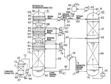
FIG. 1 is a configuration drawing showing a main
portion of a decarbonation apparatus according to the
embodiment of the present invention. As shown in FIG. 1,
the decarbonation apparatus of the present embodiment has
an absorption tower 61, a regeneration tower 62, and a
cooling tower 63.
Although details will be described later, the
decarbonation apparatus of the present embodiment is
characterized in that a water washing section of the
absorption tower 61 has a two-stage structure,, i.e., a
first-stage water washing section 64 and a second-stage
water washing section 65; that washing water of the
second-stage water washing section 65 is withdrawn and
supplied to the first-stage water washing section 64; that
regeneration tower refluxed water is supplied as washing
12
rn m
' CA 02393626 2002-06-05
water to the second-stage water washing section; and that
demisters 83, 84 and 85 are installed at outlets of a carbon
dioxide absorption section 73, the first-stage water
washing section 64 and the second-stage water washing
section 65.
In detail, a combustion exhaust gas generated in
thermal power equipment or boiler equipment is supplied to
the cooling tower 63 via an exhaust gas supply line 66.
Water is stored at the bottom 67 of the cooling tower 63.
This water is scooped up by a circulating pump 68, cooled
by a heat exchanger 69, and then supplied to a charging
section 71 through a nozzle 70. As a result, the combustion
exhaust gas is cooled in the charging section 71 upon
countercurrent contact with cooling water diffused from the
nozzle 70. Then, the combustion exhaust gas is supplied
through an exhaust gas supply line 72 to the carbon dioxide
absorption section 73 provided in a lower portion of the
absorption tower 61.
The combustion exhaust gas supplied to the
absorption tower 61 ascends within the absorption tower as
indicated by dotted arrows in the drawing. On the other
hand, a regenerated absorbing solution(an aqueoussolution
of an amine compound) reserved at the bottom 76 of the
regeneration tower 62 is transported by an absorbing
solution supply pump 77 provided in an absorbing solution
supply line 74. The transported regeneration absorbing
solution is cooled by a heat exchanger 78 and a heat
13
;an i~
CA 02393626 2002-06-05
exchanger 79, and then supplied to the carbon dioxide
absorption section 73 through a nozzle 75 provided at the
outlet of the carbon dioxide absorption section 73. As a
result, the combustion exhaust gas and the absorbing
solution make vapor-liquid contact (countercurrent
contact ) in the carbon dioxide absorption section 73 . Thus ,
carbon dioxide contained in the combustion exhaust gas is
absorbed into the absorbing solution and removed thereby.
Examples of the amine compound contained in the
absorbing solution are alcoholic hydroxyl group-containing
primary amines such as monoethanolamine and 2-amino-2-
methyl-1-propanol, alcoholic hydroxyl group-containing
secondary amines such as diethanolamine and 2-
methylaminoethanol, alcoholic hydroxyl group-containing
tertiary amines such as triethanolamine and N-
methyldiethanolamine, polyethylenepolyamines such as
ethylenediamine, triethylenediamine and
diethylenetriamine, cyclic amines such as piperazines,
piperidines and pyrrolidines, polyamines such as
xylylenediamine, amino acidssuch asmethylaminocarboxylic
acid, and mixtures of them. Any of these amines is used
usually as 10 to 70% by weight of an aqueous solution. To
the absorbing solution, carbon dioxide absorption
promoters or corrosion inhibitors may be added, and
methanol, polyethylene glycol and sulfolane may be added
as other media.
The loaded absorbing solution, which has absorbed
14
du m
CA 02393626 2002-06-05
carbon dioxide, flows downward, and is stored at the bottom
80 of the absorption tower. Then, the stored solution is
discharged by an absorbing solution discharge pump 87
provided in an absorbing solution discharge line 86, and
is heated upon heat exchange with the regenerated absorbing
solution in the heat exchanger 78. Then, the heated
solution is diffused from a nozzle 89 provided at the outlet
of a lower charging section 88 of the regeneration tower
62, flows down the lower charging section 88, and is stored
at the bottom 76 of the regeneration tower.
The loaded absorbing solution stored at the bottom
76 of the regeneration tower is heated to, for example, about
120°C by feed steam in a reboiler 90. As a result, carbon
dioxide in the loaded absorbing solution is released to
regenerate the absorbing solution. This regenerated
absorbing solution is stored at the bottom 76 of the
regeneration tower, and supplied again to the carbon
dioxide absorption section 73 of the absorption tower 61.
That is, the absorbing solution is used in a circulated
manner, and need not be discharged to the outside or supplied
from the outside, unless any loss occurs . On the other hand,
the carbon dioxide released ascends as indicated by dotted
arrows in the drawing, passes through the lower charging
section 88 and an upper charging section 91, and is
discharged to the outside of the regeneration tower through
a carbon dioxide discharge line 93 at the top 111 of the
regeneration tower.
15
CA 02393626 2005-02-16
Since the carbon dioxide at this time contains
moisture, it is cooled by a condenser (cooler) 94 provided
in the carbon dioxide discharge line 93 to condense moisture
contained in the carbon dioxide. The resulting condensate
and carbon dioxide are separated by a carbon dioxide
separator 95. High purity carbon dioxide separated from
the condensate is released to the outside of the
decarbonation process system (hereinafter referred to
simply as the outside of the system) through a carbon dioxide
release line 96, and is utilized in a subsequent step or
disposed of. The condensate is transported by a
circulating pump 206, and part of it is withdrawn toward a
regeneration tower refluxed water supply line 97. This
regeneration tower refluxed withdrawn water is cooled by
a heat exchanger 98 , and then supplied as washing water to
the top of the second-stage water washing section 65 through
a nozzle 99 provided at the outlet of the second-stage Water
washing section 65. This regeneration tower refluxed
withdrawn water has a very low amine concentration. The
remainder of the condensate is refluxed to the regeneration
tower 62 . That is , it is supplied to the top of the upper
charging section 91 through a nozzle 92 via a reflux line
100, flowed downward, and reserved at the bottom 76 of the
regeneration tower.
On the other hand, the combustion exhaust gas
deprived of carbon dioxide ( i . a . , decarbonated exhaust gas )
in the carbon dioxide absorption section 73 of the
16
~~n i~,
' CA 02393626 2002-06-05
absorption tower 61 passes through the demister 83 provided
at the outlet of the carbon dioxide absorption section 73,
and flows into the first-stage water washing section 64.
At this time, the decarbonated exhaust gas is accompanied
by a large amount of an amine vapor. That is, the
temperature rises because of the exothermic reaction
between carbon dioxide and the amine compound in the carbon
dioxide absorption section 73, so that a large amount of
the absorbing solution evaporates, ascending together with
the decarbonated exhaust gas. The moisture accompanying
the decarbonated exhaust gas at this time becomes a supply
source for washing water in the water washing section to
be described later. The temperature of the decarbonated
exhaust gas, flowing into the first-stage water washing
section 64, is about 50 to 80°C, for example.
The demister 83 removes a mist of the absorbing
solution accompanying the decarbonated exhaust gas. That
is, the absorbing solution is diffused from the nozzle 75
as a mist, and part of this absorbing solution mist
accompanies the decarbonated exhaust gas and ascends . If
the absorbing solution mist is released, unchanged, to the
outside of the absorption tower along with the decarbonated
exhaust gas, there will be a loss of the amine compound.
Thus , the demister 83 is provided at the outlet of the carbon
dioxide absorptionsection to remove the absorbing solution
mist accompanying the decarbonated exhaust gas. The
moisture (absorbing solution) removed by the demister 83
17
CA 02393626 2005-02-16
flows downward, and is reserved at the bottom 80 of the
absorption tower.
In the first-stage water washing section 64,
reserved water in a liquid reservoir 81 in the first-stage
Water washing section 64 is transported by a circulating
pump 102 provided in a circulation line 101. The
transported water is cooled by a heat exchanger 103, and
then supplied as washing water to the top of the first-
stage water washing section 64 through a nozzle 104 provided
at the outlet of the first-stage water washing section 64.
As a result, the washing water and the decarbonated exhaust
gas make countercurrent contact in the first-stage water
washing section 64. Consequently, the temperature of the
decarbonated exhaust gas lowers, whereupon a water vapor
accompanying the decarbonated exhaust gas condenses. Also,
the amine compound accompanying the decarbonated exhaust
gas is recovered. The resulting condensate and the
diffused washing water flow downward, and are stored in the
liquid reservoir 81.
The reserved water in the liquid reservoir 81 is
maintained at a constant water level. That is, when the
reserved water in the liquid reservoir 81 increases and
reaches more than the constant water level, the reserved
water is overflowed to the bottom 80 of the absorption tower
via a reserved water discharge line 105 . The reserved water
in the liquid reservoir 81 may be transported to the bottom
80 of the absorption tower by a pump.
18
ui m~
CA 02393626 2002-06-05
Most of the amine compound accompanying the
decarbonated exhaust gas is recovered in the first-stage
water washing section 64. At this time, the amine
concentration of the reserved water (washing water) in the
liquid reservoir 81 is high . Thus , the amine vapor pressure
becomes so high because of vapor-liquid equilibrium that
the amine concentration in the decarbonated exhaust gas
cannot be decreased any further. That is, the single-stage
water washing section alone cannot fully decrease the amine
concentration in the decarbonated exhaust gas. In the
present embodiment, therefore, the water washing section
has a two-stage structure, the first-stage water washing
section 64 and the second-stage water washing section 65.
The decarbonated exhaust gas having amine recovered in the
first-stage water washing section 64 passes through the
demister 84 provided at the outlet of the first-stage water
washing section 64, and flows to the second-stage water
washing section 65.
The demister 84 removes a mist of the washing water
accompanying the decarbonated exhaust gas. That is, the
washing water is diffused from the nozzle 104 as a mist,
and part of this washing water mist accompanies the
decarbonated exhaust gas and ascends . If the washing water
mist is released, unchanged, to the outside of the
absorption tower along with the decarbonated exhaust gas ,
there will be a loss of the amine compound. Thus, the
demister 84 is provided at the outlet of the first-stage
19
iVl I~ ~
r 1
CA 02393626 2002-06-05
water washing section to remove the washing water mist
accompanying the decarbonated exhaust gas. The moisture
(washing water) removed by the demister 83 flows downward,
and is reserved in the liquid reservoir 81.
In the second-stage water washing section 65,
reserved water in a liquid reservoir 82 in the second-stage
water washing section 65 is transported by a circulating
pump 107 provided in a circulation line 106. The
transported water is cooled by the heat exchanger 98, and
then supplied as washing water to the top of the second-stage
water washing section 65 through the nozzle 99 provided at
the outlet of the second-stage water washing section 65.
The regeneration tower refluxed withdrawn water supplied
from the regeneration tower also merges into this washing
water. As a result, the combined washing water and the
decarbonated exhaust gas make countercurrent contact in the
second-stage water washing section 65. Consequently, the
amine compound accompanying the decarbonated exhaust gas
is recovered.
Most of the amine compound accompanying the
decarbonated exhaust gas is recovered in the first-stage
water washing section 64. In the second-stage water
washing section 65, therefore, the amine concentration of
the liquid reservoir 82, namely, the concentration of the
amine contained in the washing water supplied through the
nozzle 99, is kept very low. Thus, in the second-stage
water washing section 65, the amine concentration in the
dl I~
CA 02393626 2002-06-05
decarbonated exhaust gas is fully decreased because of
vapor-liquid equilibrium. That is, in the second-stage
water washing section 65, the amine compound can be further
recovered from the decarbonated exhaust gas released from
the first-stage water washing section 64, so that the amine
concentration in the decarbonated exhaust gas can be fully
decreased.
Furthermore, washing water in the second-stage
water washing section 65 is withdrawn and supplied to the
first-stage water washing section 64. Concretely, part of
the reserved water ( washing water ) in the liquid reservoir
82 is withdrawn, and supplied to the liquid reservoir 81
of the first-stage water washing section 64. That is, the
reserved water in the liquid reservoir 82 is maintained at
a constant water level. When the reserved water in the
liquid reservoir 82 increases and reaches higher than the
constant water level, the reserved water is overflowed to
the liquid reservoir 81 via a reserved water discharge line
108. However, this mode is not restrictive, and the
reserved water ( washing water ) in the liquid reservoir 82
may be supplied to the liquid reservoir 81 by a pump.
The decarbonated exhaust gas having amine recovered
in the second-stage water washing section 65 passes through
the demister 85 provided at the outlet of the second-stage
water washing section 65, and is released to the outside
of the system through a gas release line 110 at the top 109
of the absorption tower. The amine concentration in the
21
ae m
' CA 02393626 2002-06-05
decarbonated exhaust gas released to the outside of the
system is a very low value.
The demister 85 removes a mist of the washing water
accompanying the decarbonated exhaust gas. That is, the
washing water is diffused from the nozzle 99 as a mist, and
part of this washing water mist accompanies the
decarbonated exhaust gas and ascends . If the washing water
mist is released, unchanged, to the outside of the
absorption tower along with the decarbonated exhaust gas ,
there will be a loss of the amine compound. Thus, the
demister 85 is provided at the outlet of the second-stage
water washing section to remove the washing water mist
accompanying the decarbonated exhaust gas. The moisture
removed by the demister 85 flows downward, and is reserved
in the liquid reservoir 82.
The cooling ability of the heat exchanger 98 , for
example, is adjusted so that the amount of moisture brought
from the exhaust gas supply line 72 into the absorption tower
together with the combustion exhaust gas, and the amount
of moisture brought through the gas release line 110 to the
outside of the absorption tower together with the
combustion exhaust gas are made equal to maintain water
balance . This measure makes water discharge to the outside
or water supply from the outside unnecessary unless there
is a loss.
Moreover, the cooling ability of the heat exchanger
98 and so on are adjusted so that the temperature of the
22
~r is
v
CA 02393626 2002-06-05
decarbonated exhaust gas released through the gas release
line 110 is equal to the temperature at the inlet of the
second-stage water washing section 65. In this case, the
temperatures at the outlet and the inlet of the second-
stage water washing section 65 are equal. Thus, steam in
the decarbonated exhaust gas in the second-stage water
washing section 65 does not condense, and only the amount
of water corresponding to the regeneration tower refluxed
withdrawn water overflows and is fed to the liquid reservoir
81 of the first-stage water washing section 64. This mode
is not necessarily restrictive, and the outlet temperature
of the second-stage water washing section 65 may be adjusted
to be lower than its inlet temperature to cause condensation
of moisture in the decarbonated exhaust gas even in the
second-stage water washing section65. Through this means,
the amount of the resulting condensate may be adapted to
overflow the liquid reservoir 82 and be supplied to the
liquid reservoir 81 of the first-stage water washing
section 64.
As described in detail above, according to the
present embodiment, the water washing section has the
two-stage structure, i.e., the first-stage water washing
section 64 and the second-stage water washing section 65,
whereby the decarbonated exhaust gas is sub jetted to amine
recovery in the first-stage water washing section 64 , and
then further subjected to amine recovery in the second-
stage water washing section 65 as well. Thus, the amine
23
ago
' CA 02393626 2002-06-05
compound accompanying the decarbonated exhaust gas can be
recovered very efficiently, and the operating cost can be
reduced.
Additionally, if the water washing section remains
a one-stage structure and is given a large height only,
recovery performance for the amine compound improves.
However, the amine concentration in the washing water in
the water washing section becomes so high that the amine
concentration in the decarbonated exhaust gas cannot be
made sufficiently low because of vapor-liquid equilibrium.
These facts show that constructing the water washing
section in the two-stage form is a very effective means.
According to the present embodiment, moreover,
washing water in the second-stage water washing section 65
is withdrawn and supplied to the first-stage water washing
section 64, whereby the concentration of amine contained
in the washing water in the first-stage water washing
section 64 is decreased to enhance the amine recovery
ability in the first-stage water washing section 64. In
accordance with this advantage, the concentration of amine
contained in the washing water in the second-stage water
washing section 65 is further decreased to further enhance
the amine recovery ability as a whole.
According to the present embodiment, moreover,
regeneration tower refluxed water is supplied, as washing
water, to the second-stage water washing section 65,
whereby the concentration of amine contained in the washing
24
:ae m
CA 02393626 2002-06-05
, , ~ ,
water in the second-stage water washing section 65 is
further decreased to further enhance the amine recovery
ability in the second-stage water washing section 65.
Furthermore, washing water in the second-stage water
washing section 65 is withdrawn and supplied to the
first-stage water washing section 64, whereby the
concentration of amine contained in the washing water in
the first-stage water washing section 64 is decreased to
enhance the amine recovery ability in the first-stage water
washing section 64.
It is desirable that as described above,
regeneration tower refluxed water is supplied to the
second-stage water washing section 65, and washing water
in the second-stage water washing section 65 is withdrawn
and supplied to the first-stage water washing section 64.
However, this mode is not necessarily restrictive. Instead,
regeneration tower refluxed water may be supplied to the
second-stage water washing section 65 and the first-stage
water washing section 64 at the same time.
According to the present embodiment, moreover, the
demisters 83, 84 and 85 are installed at the outlets of the
carbon dioxide absorption section 73, first-stage water
washing section 64 and second-stage water washing section
65. This means can prevent the situation that part of the
absorbing solution mist fed to the carbon dioxide
absorption section 73 and part of the washing~water mist
fed to each of the first-stage water washing section 64 and
CA 02393626 2002-06-05
the second-stage water washing section 65 are released to
the outside of the absorption tower together with the
decarbonated exhaust gas , causing losses in water and amine
compound.
The decarbonation apparatus equipped with the amine
recovery apparatus described above is an apparatus with a
high ability to recover the amine compound and involving
a low operating cost.
The first-stage water washing section 64 and the
second-stage water washing section 65 may be in a packed
tower or in a tower with trays.
In the above embodiment , the water washing section
is formed as the two-stage structure. However, this is not
necessarily restrictive, and the water washing section may
have a structure comprising a plurality of stages not less
than three stages. In this case as well, the decarbonated
exhaust gas containing an amine compound is subjected to
amine recovery in the water washing section at a preceding
stage (a stage upstream from a decarbonated exhaust gas
f low ) , and then is further sub j ected to amine recovery in
the water washing section at a succeeding stage (a stage
downstream from the decarbonated exhaust gas flow) . That
is, recovery of the amine compound accompanying the
decarbonated exhaust gas is performed sequentially in
plural stages of water washing sections. In this case, the
regeneration tower refluxed withdrawn water may be supplied
to the water washing section in the rearmost stage among
26
n. i~
CA 02393626 2002-06-05
the plural-stage water washing sections, and washing water
may be withdrawn from the rearmost-stage water washing
section and supplied to the water washing section in the
stage preceding it, further withdrawn from the water
washing section in this stage and supplied to the water
washing section preceding to it, and so on.
In the above embodiment, absorption of carbon
dioxide contained in the combustion exhaust gas of fuel is
taken as an example for explanation. However, this is not
restrictive, and the carbon dioxide-containing gas to be
decarbonated may be a process gas such as a fuel gas, and
other various gases can be applied. The pressure of the
carbon dioxide-containing gas to be decarbonated may be an
applied pressure or an atmospheric pressure, and its
temperature may be a low temperature or a high temperature,
without any restrictions. The combustion exhaust gas at
atmospheric pressure is preferred.
[Explanation for concrete experiment examples
The present invention will be described concretely
by an experimental example, which in no way limit the present
invention.
<Experimental Example>
The following experiments were conducted as the
method of the present invention: 30 Nm'/h of a combustion
exhaust gas containing 10% carbon dioxide was supplied to
the carbon dioxide absorption section 73 of the absorption
tower 61, and brought into countercurrent contact with an
27
,~
CA 02393626 2002-06-05
aqueous solution of an alcoholic hydroxyl group-containing
secondary amine (i.e., an absorbing solution) to absorb
carbon dioxide to the aqueous solution. The residual
decarbonated exhaust gas was fed to the demister 83 at the
outlet of the carbon dioxide absorption section, then
brought into countercurrent contact with washing water at
a liquid/gas ratio of 2.2 1/Nm3 in the first-stage water
washing section 64, and passed through the demister 84 at
the outlet of the first-stage water washing section.
Further, the decarbonated exhaust gas was brought into
countercurrent contact with washing water at a liquid/gas
ratio of 2. 2 1/Nm' in the second-stage water washing section
65, passed through the demister 85 at the outlet of the
second-stage water washing section, and released to the
outside of the system. During this procedure, the
operation was performed such that the temperature of the
gas at the outlet of the first-stage water washing section
and the temperature of the gas at the outlet of the
second-stage water washing section were both 46°C. Also,
regeneration tower refluxed withdrawn water was fed at 1. 1
1/h to the second-stage water washing section 65, while
washing water of the second-stage water washing section 65
was withdrawn and supplied to the first-stage water washing
section 64. As a result, the amine concentration in the
decarbonated exhaust gas released from the absorption tower
61 to the outside of the system was 8 ppm.
<Comparative Example 1>
28
~ir ~s
CA 02393626 2002-06-05
The same procedure as in the above experimental
example was performed, except that the water washing
section was a one-stage structure, and the regeneration
tower refluxed withdrawn water was supplied to the one-
stage water washing section, as the conventional method.
As a result, the amine concentration in the decarbonated
exhaust gas released from the absorption tower 61 to the
outside of the system was 25 pprn, a higher value than in
the above-mentioned Example.
<Comparative Example 2>
The same procedure as in the above experimental
example was performed, except that the liquid withdrawn
from the second-stage water washing section (washing water)
was not supplied to the first-stage water washing section
64. As a result, the amine concentration in the
decarbonated exhaust gas released from the absorption tower
to the outside of the system was 11 ppm. This value was
sufficiently low compared with the above Comparative
Example 1, but was higher than in the above-mentioned
experimental example. These findings were able to confirm
the effectiveness of withdrawing washing water of the
second-stage water washing section 65 and supplying it to
the first-stage water washing section 64.
The results of the Experimental Example and
Comparative Examples 1 and 2 are summarized in [ Table 1 ] .
By constituting the water washing section into the two-
stage structure, the concentration of amine released to the
29
.a~
CA 02393626 2002-06-05
outside of the system can be made sufficiently low. Also,
washing water of the second-stage water washing section 65
is withdrawn and supplied to the first-stage water washing
section 64, whereby the concentration of amine released to
the outside of the system can be made even lower.
[Table 1]
Exp. Comp. Comp.
_ Ex. 1 Ex. Ex.
1 2
First-stage water washing section 2.2 2.2 2.2
liquid/gas ratio (1/Nm3)
First-stage water washing section 46 46 46
outlet gas temperature (C)
Second-stage water washing section 2.2 - 2.2
liquid/gas ratio (1/Nm3)
Second-stage water washing section 46 - 46
outlet gas temperature (C)
Regeneration tower refluxed 1.1 1.1 1.1
withdrawn water flow rate (1/h)
Supply of second-stage water washingYes - No
section withdrawn liquid to first-
stage water washing section
Amine concentration of carbon 8 25 11
dioxide absorption tower outlet gas
(PPm)
Industrial Applicability
As described above, the present invention relates
to an amine recovery method and apparatus, and a
decarbonation apparatus equipped with the amine recovery
apparatus. This invention is useful when applied to
recovering an amine compound accompanying a decarbonated
exhaust gas in a decarbonation process in which carbon
dioxide is removed from a gas containing carbon dioxide with
":
CA 02393626 2002-06-05
the use of an amine compound-containing absorbing solution.
31